Quotation form
Send an inquiry
Start with the basics. Our team can follow up for missing drawings, standards or packing details.
Submitted details are used only for quotation, technical review and project communication.
Start with the basics. Our team can follow up for missing drawings, standards or packing details.
Submitted details are used only for quotation, technical review and project communication.
Use this selector page to compare drop out fuse cutout bodies, polymer and porcelain variants, 300A and 400A routes, protected and enclosed designs, windproof cutouts, bracket accessories and fuse-link paths before RFQ release.
Cutout bodies, protected routes, accessories and fuse links are separated.
Only the windproof dimension view is clean enough for Drawing.
Selector page under Distribution Switching Equipment.
Rating boundaries and document review aligned to the DSE SOP.
Open each product path to check technical parameters, rating boundaries and Drawing status. Product card images open the same modal as View details.
standard drop out fuse cutout parent cutout route for overhead distribution protection where fuse tube, upper and lower contacts, insulator body and mounting bracket must be confirmed together.
ANSI and IEC standard fuse cutout standard coordination route for buyers who need the cutout package checked against destination standard and feeder practice.
polymer drop out fuse cutout silicone or polymer insulation route for outdoor feeders where lighter housing, shed profile and site exposure drive the selection.
porcelain drop out fuse cutout route for RW12 11-33 kV feeder protection where ceramic insulation, contact hardware and fuse tube fit are selected together.
300A expulsion fuse cutout route for higher-current branch protection where the 300A current path, fuse tube and contact duty must be checked as one package.
V type drop out fuse bracket accessory bracket path for mounting geometry review; it does not define fuse-link current rating or full cutout voltage class by itself.
double column cutout fuse route for support geometry where two insulator columns and base spacing must be confirmed before order release.
RW5 33kV fuse cutout route for 33 kV pole-mounted protection where dual insulator support and blade geometry are part of the selection boundary.
HRW12 12kV to 38kV drop out fuse cutout route for multi-voltage selection where the model row, 200A current row and 12.5 kA interruption row must stay together.
400A pole mounted fuse cutout 400A route for enclosed pole-mounted protection where housing, contact package and current path must be reviewed together.
NT fuse switch disconnector pole mounted switch-disconnector path for low-voltage or feeder-mounted fuse switching where switch body, bracket and fuse package must be confirmed.
protected cut out fuse protected cutout route for insulated or guarded cutout installations where the protected housing and cable path decide the final package.
outdoor enclosed expulsion fuse cutout enclosed expulsion route for installations where a closed body and expulsion fuse function are required together.
windproof fuse cutout route for high-wind outdoor installations where HGRW-35/200, 40.5 kV, 200A and 12.5 kA rows must stay linked to the cropped dimension drawing.
fuse link for drop out fuse cutout accessory fuse link path for fuse element selection; it does not define cutout voltage class or mounting body by itself.
The page separates feeder protection position, cutout body, bracket accessory and fuse-link coordination before model selection.
Confirm whether the cutout protects a branch, transformer tap, service point or protected enclosure route.
Select standard, ANSI IEC, polymer, porcelain, expulsion, protected, enclosed, windproof or RW5/HRW12 path.
V bracket and fuse-link paths support the cutout package but do not define full electrical rating alone.
Only the windproof route has a clean processed Drawing view; all other paths stay SPEC-only.
Use the matrix to decide which modal should be opened first. Keep product path, rating data and accessory rows separate.
Use when the first decision is destination standard, feeder voltage, current row and fuse-link compatibility.
Use when housing material, creepage distance, shed profile and site exposure determine the product route.
Use when current path and contact package are the first constraint before voltage and breaking duty review.
Use when site layout requires guarded body, enclosure or cable entry detail around the fuse path.
Use when high-wind condition and the HGRW dimension view must be checked before release.
Use only after the cutout body has been selected; they do not define full cutout rating alone.
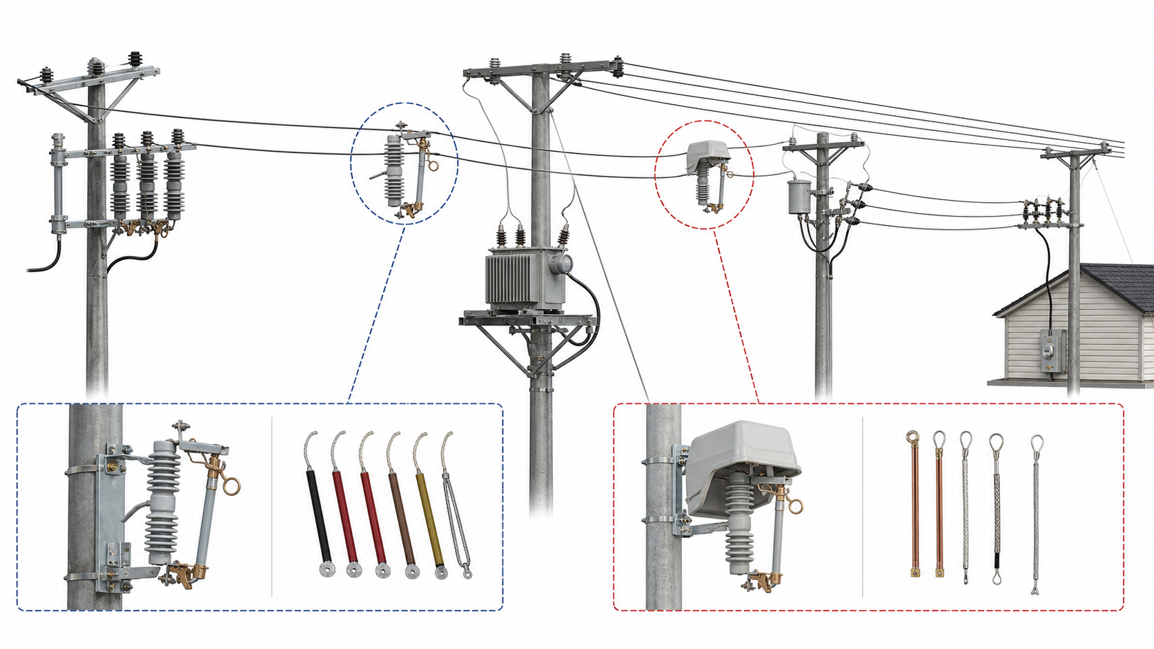
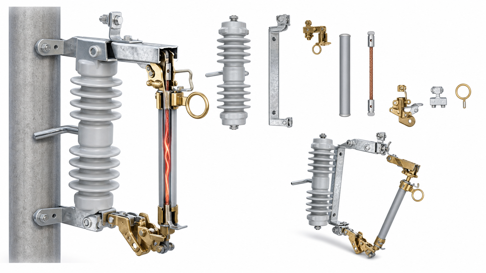
A drop out fuse cutout combines an insulator body, upper contact, lower hinge, fuse tube and pull ring. When the fuse element melts, the tube releases and drops open to show the branch is isolated.
Upper and lower contacts carry normal current and must match the current row and fuse tube route.
The fuse tube supports the fuse link and drops open after operation, giving visible isolation for maintenance review.
Mounting bracket, pole hardware and phase spacing decide whether a standard, V-type or special support route fits.
The same page contains full cutout bodies and accessory paths. Do not assign voltage class, current row or breaking duty from an accessory image alone.
Voltage class, rated current, breaking duty, creepage distance and fuse tube route belong to the selected cutout body.
Bracket paths define mounting geometry and hardware. They do not define fuse-link current rating or complete cutout duty.
Fuse links define protection coordination and current range. They do not define cutout voltage class by themselves.
Protected and enclosed bodies need separate housing, cable entry and service condition review before final model release.
Use HGRW model, 40.5 kV, 200A and 12.5 kA rows only with the confirmed windproof route.
Scanned pages remain internal unless they are processed into clean English text or clean drawing views.
Product photos, technical PDFs, rating tables, accessory pages and one windproof dimension view were reviewed. Only buyer-facing terms are used in page copy.
Used where photos or product renderings show the actual route clearly.
Voltage, current and breaking rows are kept inside their matching product path.
Technical PDFs and accessory sheets support the modal data and RFQ checklist.
Only the processed windproof dimension view appears as a Drawing tab.
Send the data below so XIYA POWER can return the suitable product path, drawing check, quotation boundary and document list.
It protects an overhead distribution branch, transformer tap or feeder section by opening the fuse tube after the fuse element operates.
Only when a clean English drawing or a clean processed drawing view is available. On this page, the windproof route is the only product path with a public Drawing tab.
No. Bracket and fuse-link rows are accessory paths. The cutout body, voltage class, current row and breaking duty must be confirmed separately.
Send product path, system voltage, rated current, breaking duty, fuse-link type, bracket or enclosure route, drawing need, standard and quantity.
Send product path, voltage, current row, breaking duty, fuse-link type, bracket or enclosure route, drawing need and quantity so XIYA POWER can return the suitable path, drawing check and quotation boundary.