Quotation form
Send an inquiry
Start with the basics. Our team can follow up for missing drawings, standards or packing details.
Submitted details are used only for quotation, technical review and project communication.
Start with the basics. Our team can follow up for missing drawings, standards or packing details.
Submitted details are used only for quotation, technical review and project communication.
Use this selector to separate indoor AIS, SF6, puffer, outdoor air, fuse-combination, manual IACM, horn-gap, accessory, PGS, indoor vacuum and outdoor vacuum load break switch paths before confirming ratings and drawings.
This category works best as one direct selector page. Some routes have full rating rows, some are image-supported, and some are accessory or cross-use paths.
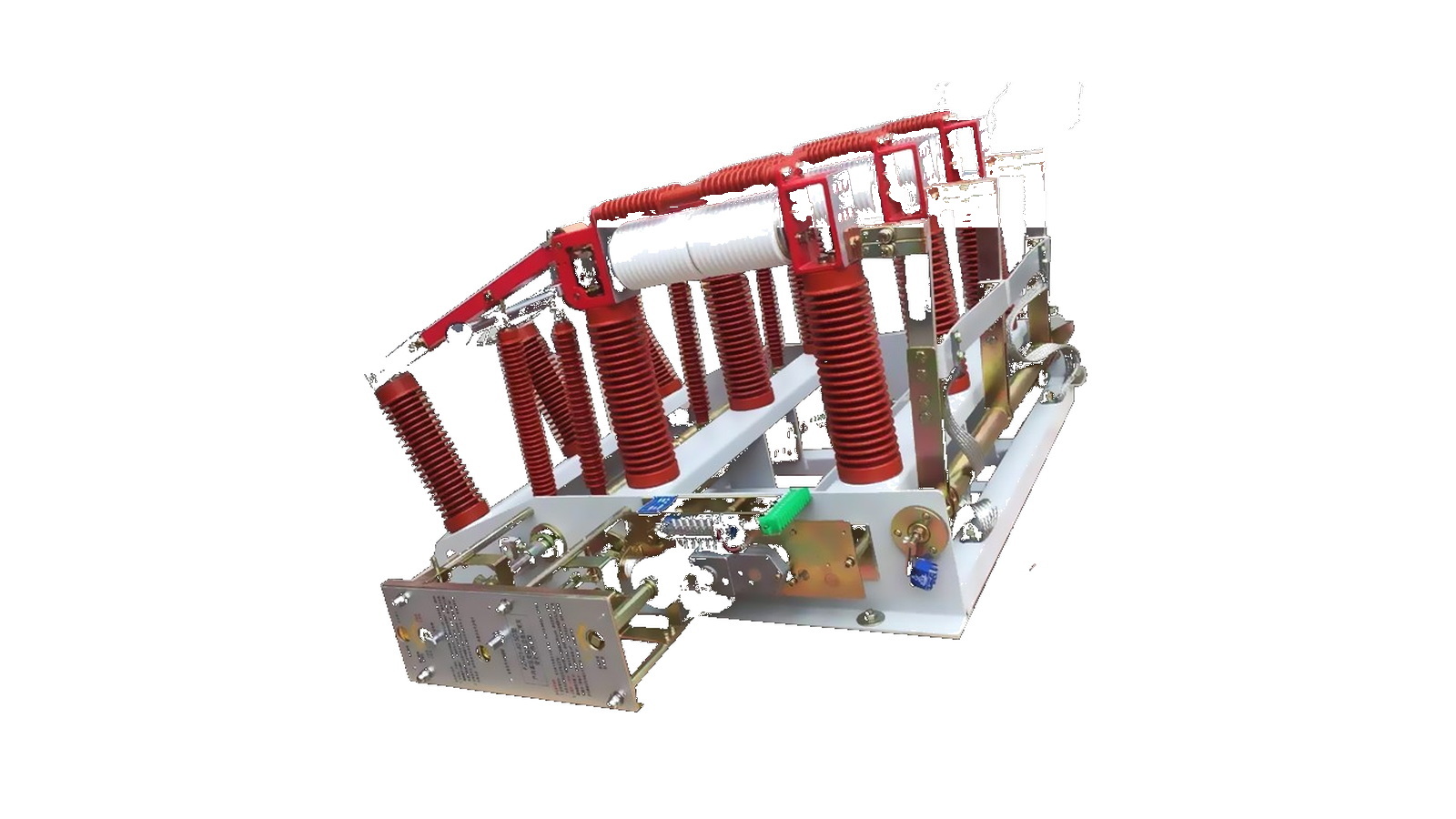
Indoor high-voltage load switch path for cabinet switching, line protection and fuse-combination review where the FN7-12 indoor LBS family is identified.
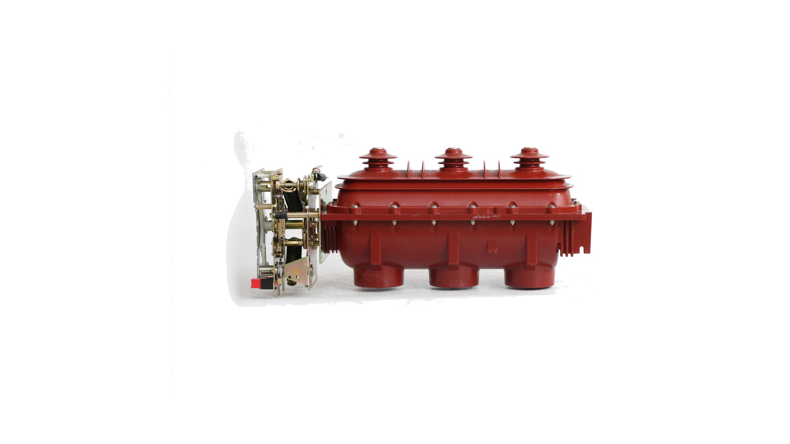
Gas-insulated load break switch path for compact distribution equipment where the switching chamber and insulation medium define the route.
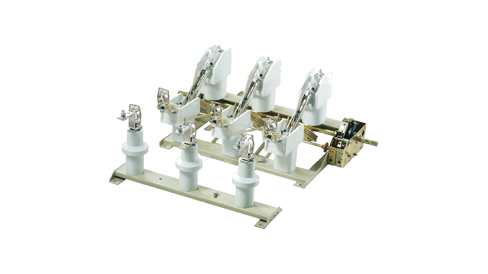
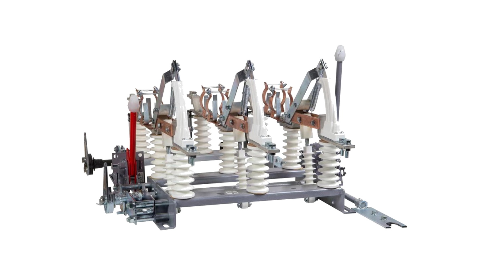
Indoor three-pole puffer load isolator path where the puffer mechanism and indoor cabinet fit are the first selection questions.
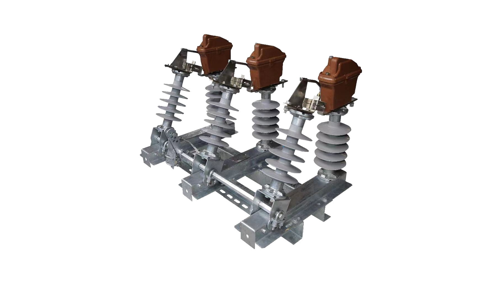
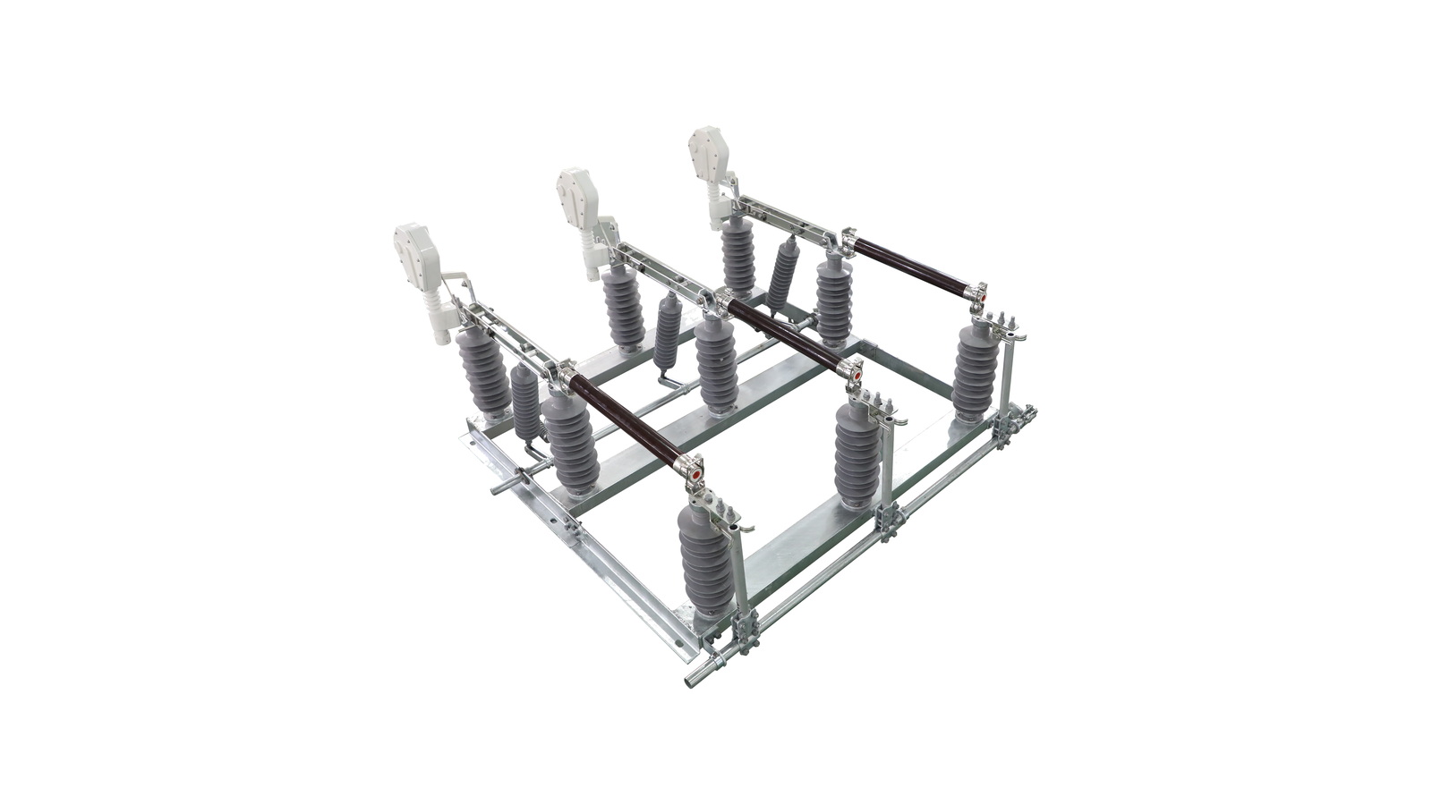
Outdoor air load break switch route for line switching where visible arc-chute hardware, pole mounting and operating linkage drive the choice.
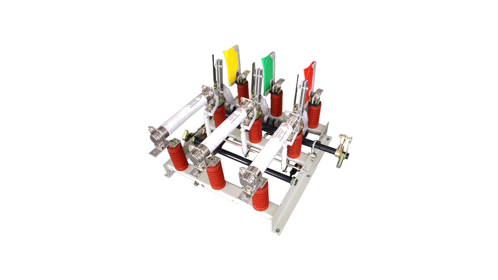
Medium-voltage air load break switch with fuse path for projects where switching duty and fuse protection are selected together.
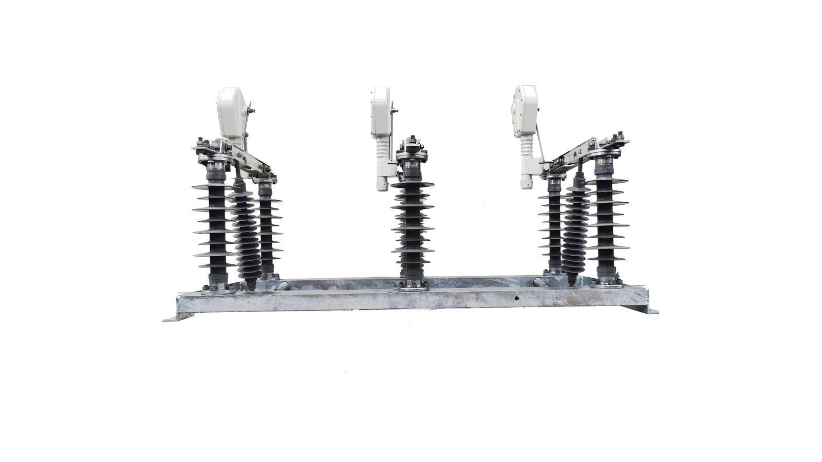
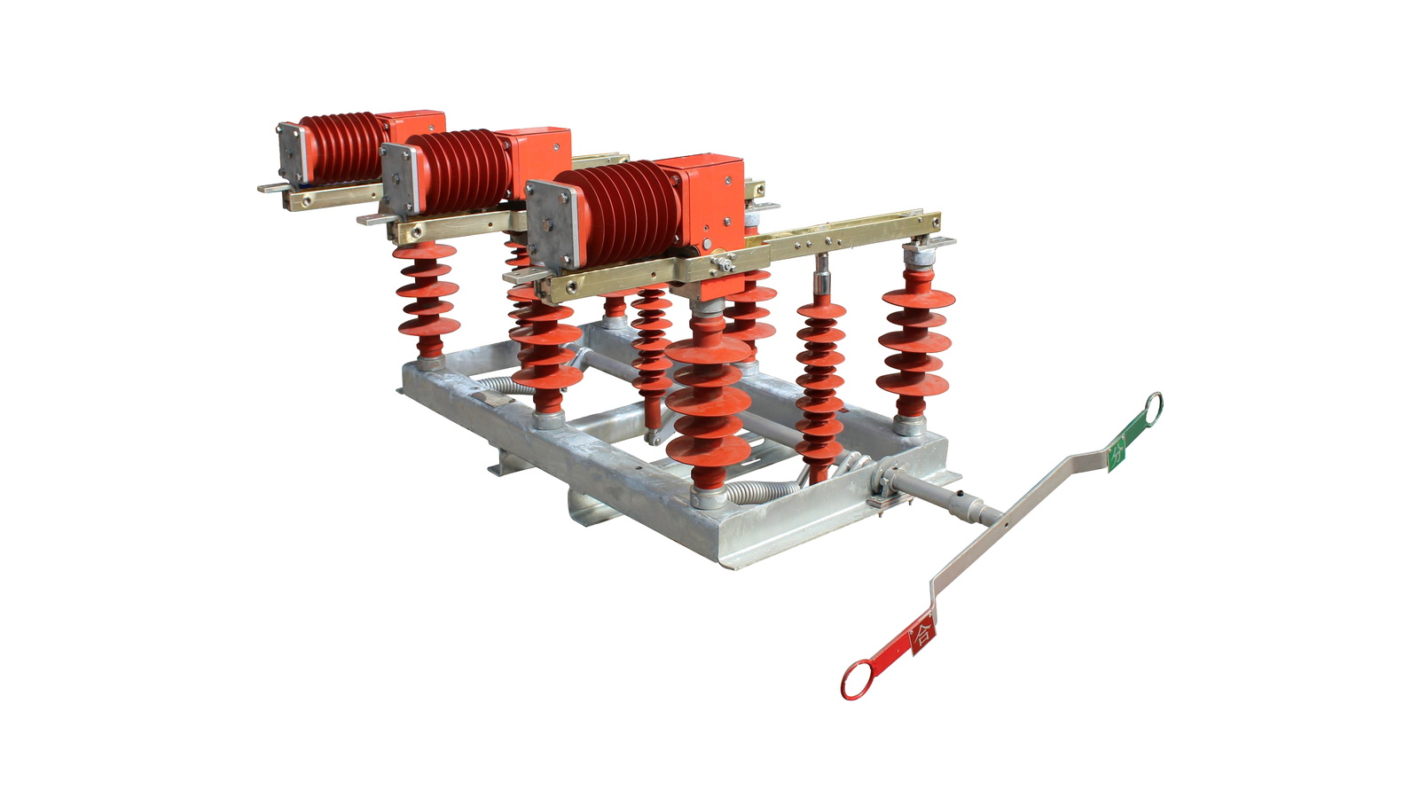
Three-pole outdoor air-break load isolator path for projects where product identity is clear but a complete public rating table is not available.
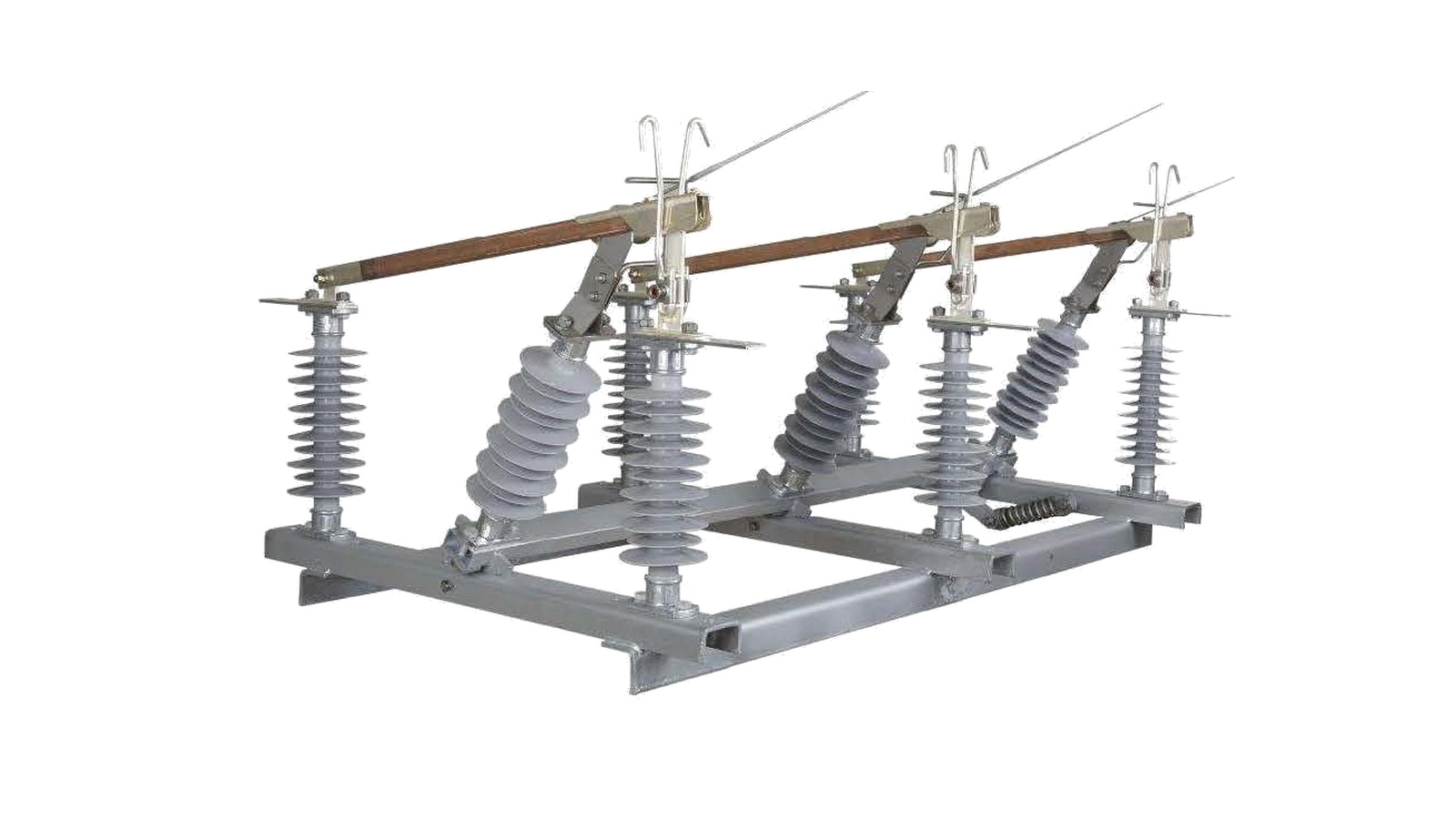
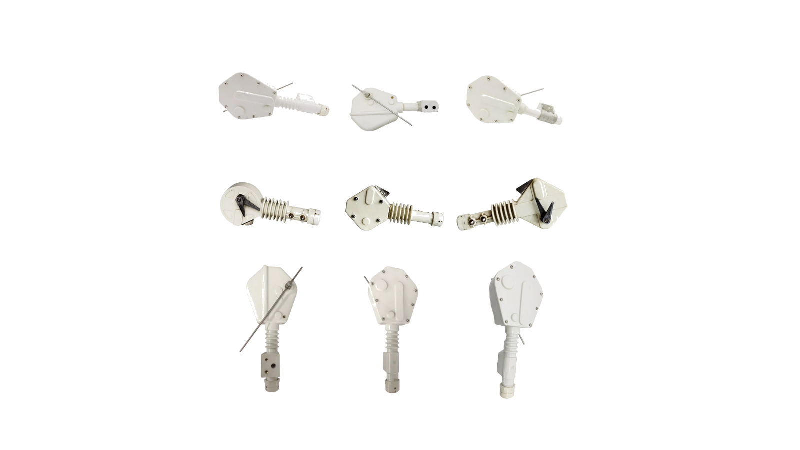
Manual outdoor IACM load break switch path with arcing-horn structure, polymer insulation and rod operation for overhead-line switching.
Horn-gap fuse switch route for adjacent fuse switching material where the visual product path is useful but full rating rows are not present.
Accessory and replacement-parts route for load break switch mechanisms, contacts, linkage parts and support hardware.
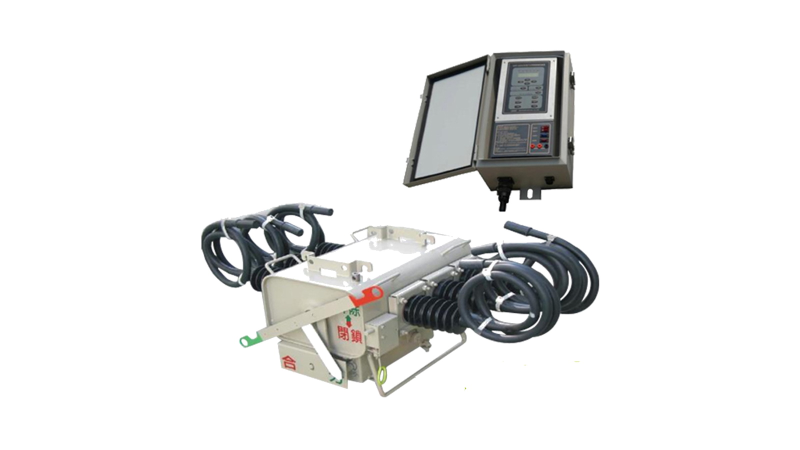
Pole-mounted SF6 PGS path for smart-grid or feeder automation projects where LBS duty crosses into distribution automation scope.
Indoor vacuum load break switch path for FZN/FZRN style switchgear applications where vacuum interruption and cabinet fit need to be checked together.
Outdoor vacuum load break switch path for FZW32 12 kV and 40.5 kV feeder switching with visible disconnecting fracture and pole mounting.
The page keeps every route under /distribution-switching-equipment/load-break-switches/ and does not push these products into the disconnect-switch hierarchy.
Product routes were checked against the Load Break Switches reference set.
Content, modal data, processed images, Drawing tabs and schema were reviewed together.
Ratings come from rating tables, readable PDFs, DOCX extracts, file titles or order-sheet confirmation.
Drawing tabs appear only where clean English drawings or clean cropped drawing views are available.
The application question comes first: indoor cabinet, outdoor feeder, ring network, fuse protection, manual overhead operation, automation or accessory replacement.
Separate load switching from visible no-load isolation. If the equipment is only for isolation, compare disconnect switch pages instead.
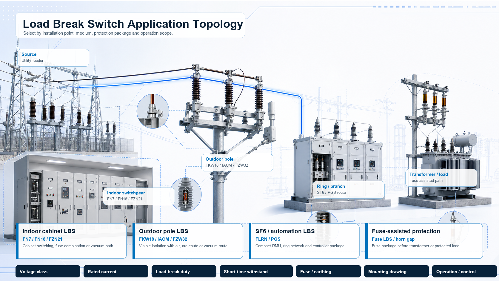
Use FN7, FN18 or FZN21 when the switch sits inside a panel or switchgear cabinet.
Use FKW18, IACM, FZW32 or three-pole outdoor air paths when the site is an overhead feeder.
Use fused or horn-gap routes only when the project needs switching plus fuse protection review.
This matrix is intentionally thin. It tells the engineer which product family to open, then the modal keeps the rating boundary for that product path.
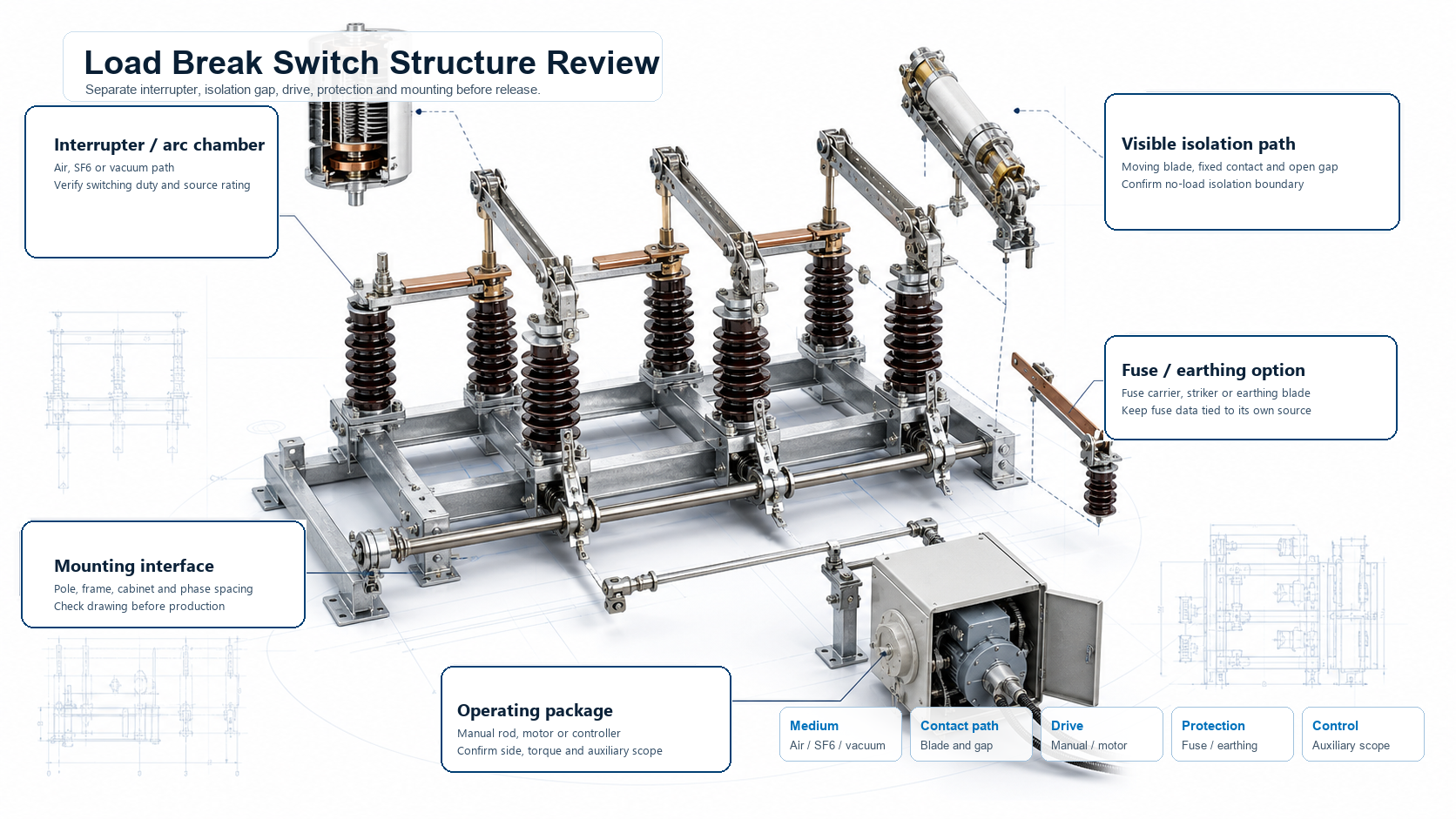
After the route is selected, check the switching chamber, contact path, operating drive and mounting interface from the matching technical documents.
Use these checks before the product path is released.
The page does not reuse one product table across the whole category. Each modal states what the current documents support.
Do not mix puffer, fuse-combination and vacuum values unless the order sheet names the same family.
Pole spacing, support height, operation side and drawing status decide the release package.
Clean product images are used for route recognition. Scanned pages, French sheets and Chinese drawings remain internal unless they can be processed into a usable English or clean drawing view.
The main page cards avoid scan pages and scanned document screenshots.
Image-supported routes do not receive invented voltage or current rows.
FN7, FN18, FKW18, FZN21 and FZW32 include Drawing tabs. IACM stays SPEC-only because the available drawing-like documents are French.
These routes are not moved under disconnect switches, even when a reference name includes isolator or disconnecting fracture.
Send the product route and the switching duty first, then match the medium, rating row, operation method and mounting interface.
Indoor, outdoor, SF6, vacuum, fused, horn-gap, accessory or PGS route.
Air, puffer, SF6 or vacuum must match the feeder application.
Do not copy values across unrelated product routes.
Cabinet, pole, cross-arm, support height, operation side and controller scope decide the package.
A load break switch opens and closes load current in a medium-voltage distribution feeder, ring network or transformer branch. Select it by installation point, interruption medium, rated current, load-breaking duty, short-time withstand, fuse or controller package, operating method and mounting interface.
It is a direct category selector under Distribution Switching Equipment. This category includes 12 load break switch routes, many without another clean subcategory layer, so this page keeps the routes in one engineering selector.
Drawing tabs are shown only where a clean drawing or a cleanly cropped English drawing view is available. French, Chinese, scanned or poster-style pages stay internal and the modal remains SPEC-only.
No. Accessories and parts support compatibility review only. Voltage, current and withstand duty must come from the matching switch family or project order sheet.
Start from the installation point and interruption medium. Indoor cabinets use indoor AIS or vacuum routes, outdoor pole feeders use air, IACM or vacuum routes, and compact or automation projects may use SF6 or PGS paths.
Send the product route, system voltage, rated current, interruption medium, switching duty, fuse or controller requirement, mounting interface, operation side, drawing status, quantity and destination standard.
Send the route, system voltage, rated current, interruption medium, switching duty, fuse or controller requirement, mounting interface, operation side, available drawing and destination standard. XIYA will return the suitable load break switch path and documentation boundary.