Quotation form
Send an inquiry
Start with the basics. Our team can follow up for missing drawings, standards or packing details.
Submitted details are used only for quotation, technical review and project communication.
Start with the basics. Our team can follow up for missing drawings, standards or packing details.
Submitted details are used only for quotation, technical review and project communication.
This direct DSE selector compares four arrester paths and five monitoring accessory paths by system position, rating boundary, image status and RFQ inputs.
This category stays as one direct selector page. Each modal keeps its own system role, rating data boundary and RFQ confirmation list.
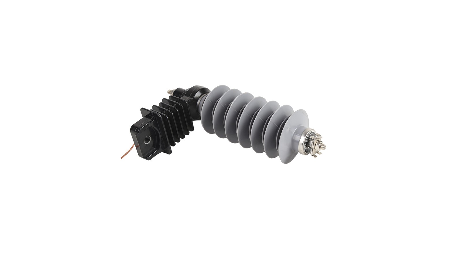
Line type surge arrester path for overhead distribution feeder protection where the MOV column, polymer housing, bracket and earthing lead must match the feeder insulation duty.
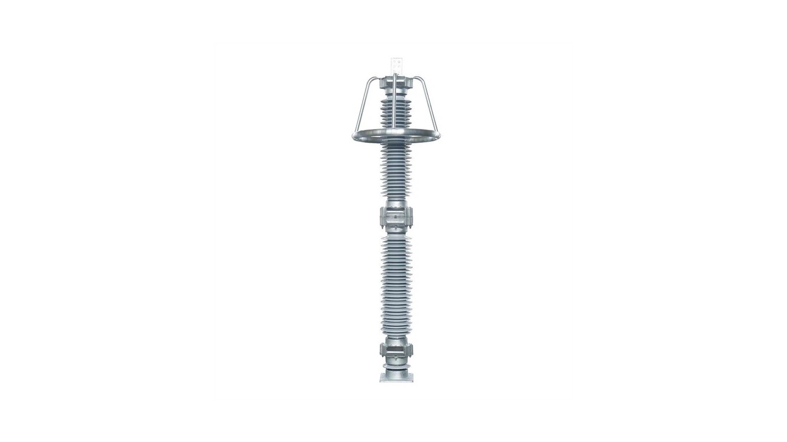
Station type surge arrester path for substation bay protection where higher insulation coordination, base fitting and station grounding must be checked together.
Low Voltage surge arrester path for service entrance, low-voltage panel or downstream auxiliary protection where pole count and AC/DC system type decide the selected device.
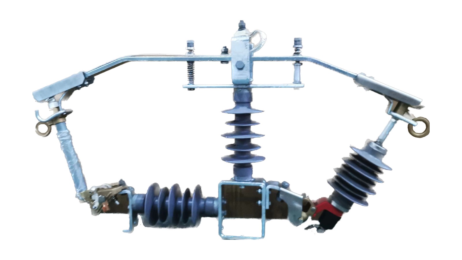
Combi cut-out and surge arrester path for pole-mounted fuse cutout assemblies where protection and overvoltage clamping are packaged in one feeder branch arrangement.
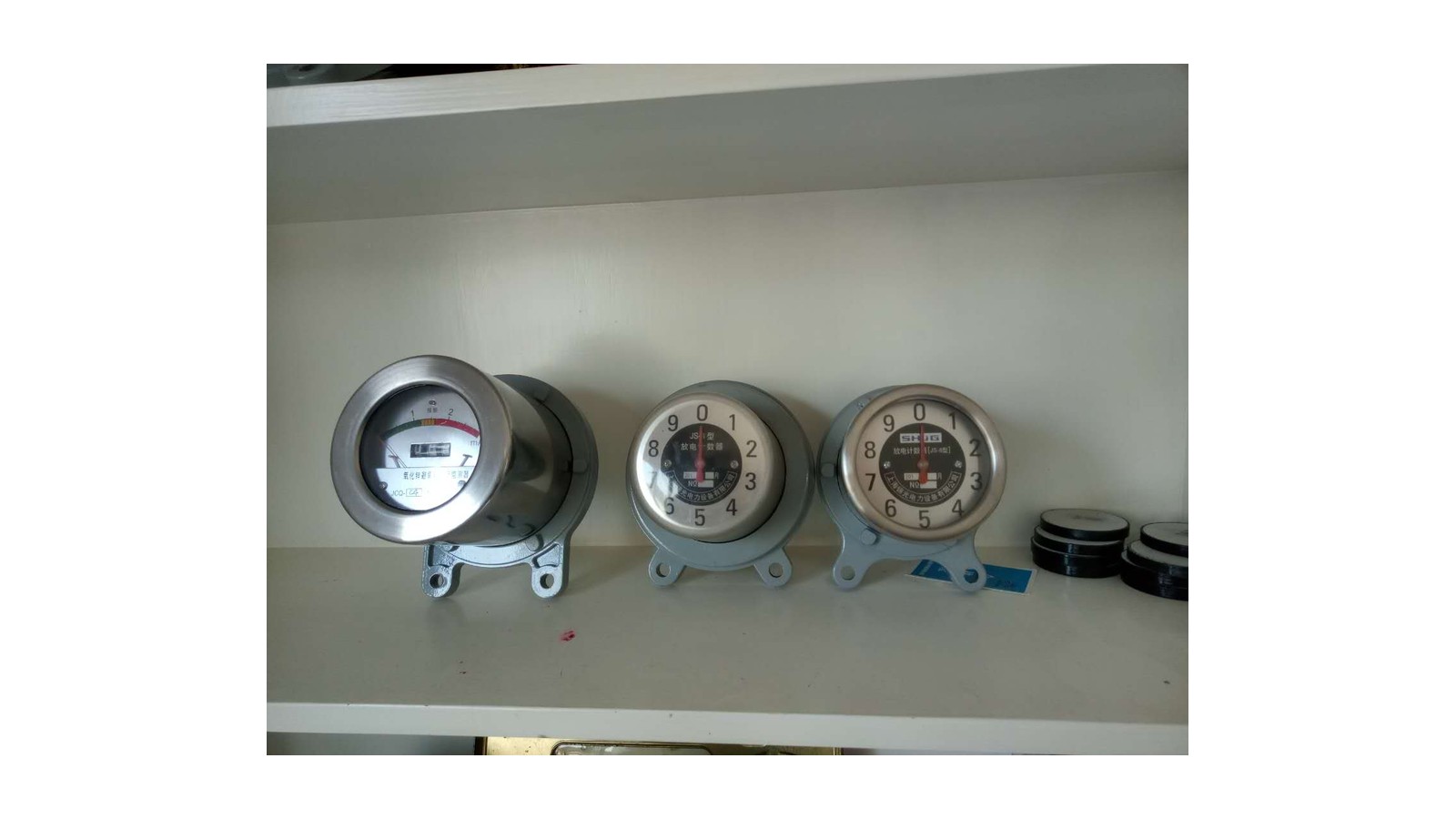
Accessory family for arrester discharge counters and online monitors. It supports monitoring function selection and does not define the main arrester residual-voltage rating.
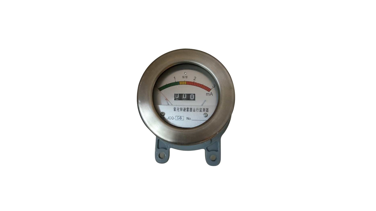
JCQ monitor path for online leakage-current observation and arrester operation counting across multiple high-voltage classes.
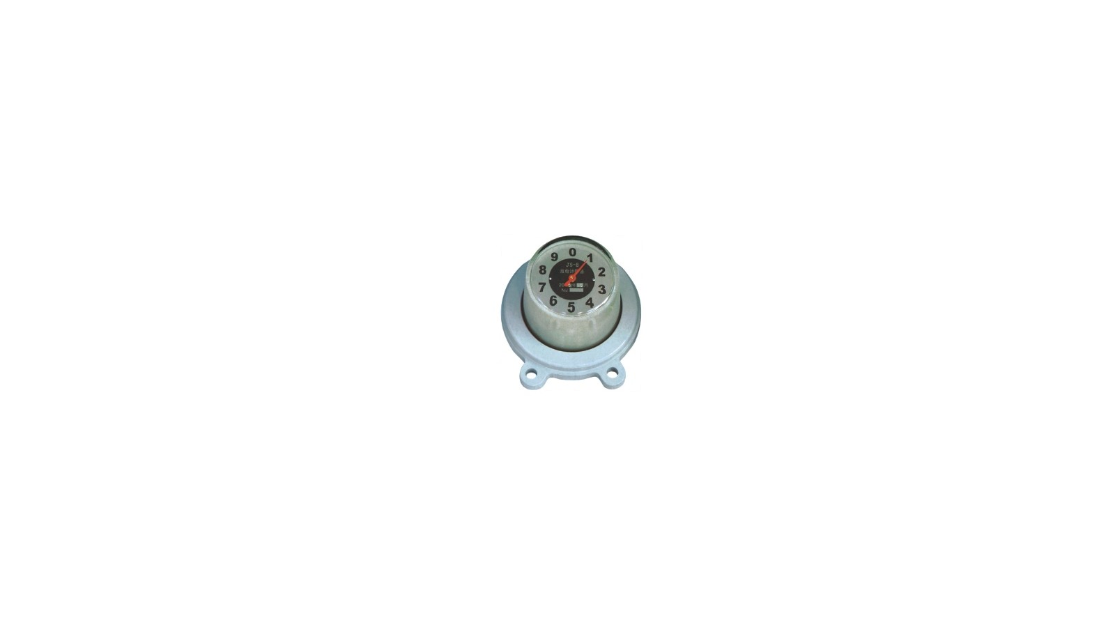
JS-8 counter path for recording arrester discharge operations on the grounding side below the arrester.
JSZ-8 counter with indicator path where the base counter function is combined with visible power or fault indication.
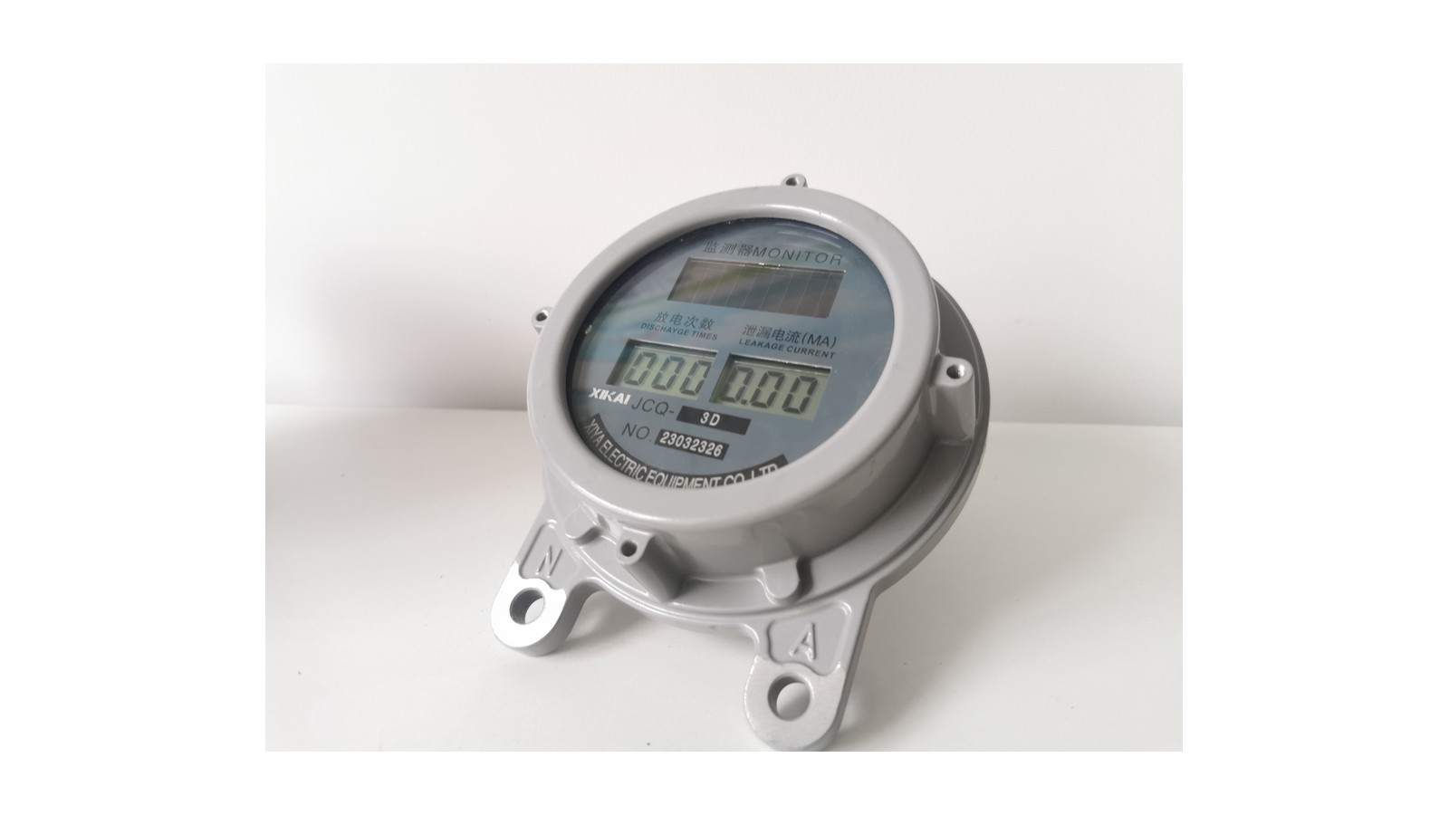
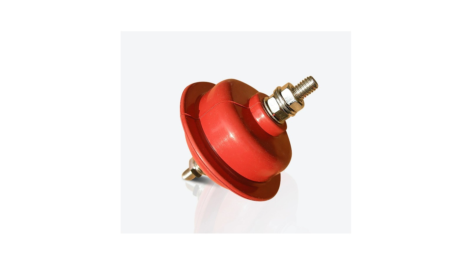
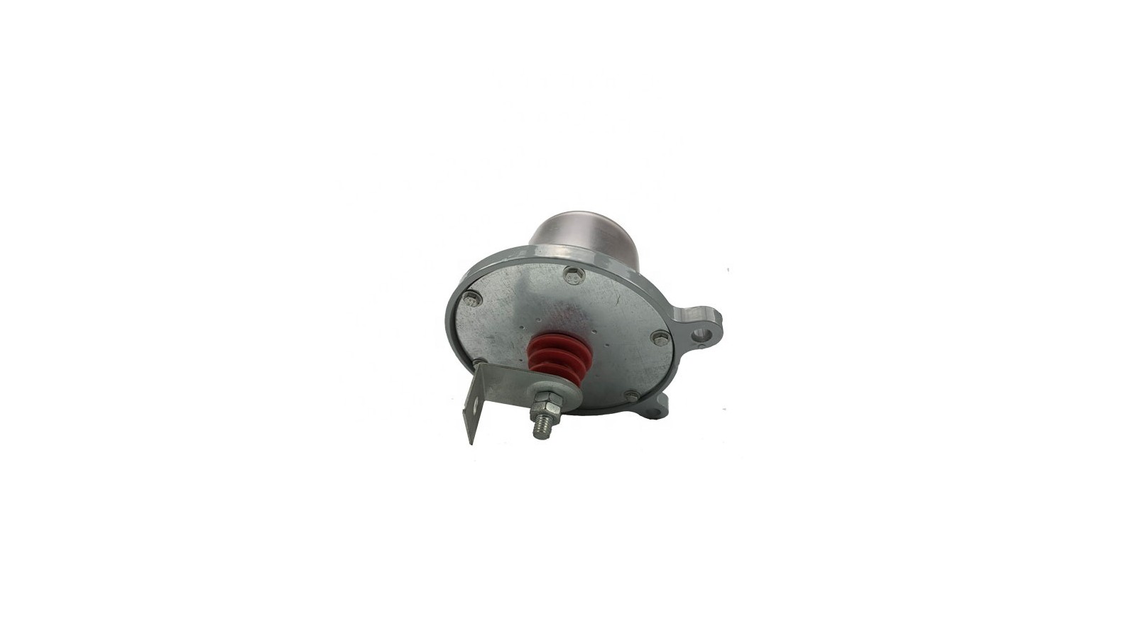
PV arrester counter path for solar station monitoring where the device is installed between surge arrester and earth and the PV station package decides final wiring.
The page stays under /distribution-switching-equipment/surge-arresters/ because the current data supports category-level selection, not forced subpages.
Product routes were checked against the Surge Arresters reference set.
Content, modal data, processed images and schema were reviewed together.
Chinese title-block drawings and mixed scan pages stay internal.
Monitor or counter selection stays separate from arrester voltage and residual-voltage data.
The placement question comes first: overhead feeder, substation bay, LV cabinet, fuse cutout assembly, grounding-side counter or PV station monitor.
Separate overvoltage clamping duty from monitoring duty before selecting the product modal.
Use these rows when the device must clamp overvoltage and discharge surge current.
Use these rows when the project needs operation count, leakage-current monitoring or visible indication.
Confirm the grounding path before selecting counter or monitor accessories.
This matrix tells the engineer which product family to open first. The modal then keeps the data boundary for that route.
Use this sequence to separate arrester structure from monitor accessories: the MOV column clamps the surge, the housing and shed profile manage insulation, the disconnector or counter interface sits below the arrester, and the earthing path discharges current safely.
Confirm these elements before releasing a product path or accessory path.
The page does not reuse accessory data as arrester data. Each route states what the available documents support and what the RFQ must confirm.
Line, station, LV and cut-out combination rows cannot inherit each other’s rating data.
Use JCQ, JS-8, JSZ-8 and PV rows only after the main arrester route is known.
Clean product images are used for route recognition. Scanned pages, Chinese-only drawings and mixed instruction pages remain internal unless they can be processed into usable English or clean drawing views.
Card images avoid document screenshots and keep the product route visible.
Image-only paths require order-sheet confirmation before voltage or discharge-current release.
No product path exposes a Drawing tab until clean English release material is available.
JS-8, JSZ-8, JCQ and PV monitor rows do not define the main arrester rating.
Send the product route and system position first, then match voltage, discharge duty, housing, mounting and monitoring accessories.
Line, station, LV, cut-out combination, JCQ, JS-8, JSZ-8 or PV counter route.
Clamp surge current for arrester routes or count/monitor for accessory routes.
Do not copy values across unrelated voltage classes or accessory families.
Base, bracket, earth lead, counter position and site conditions decide the final package.
A surge arrester clamps lightning or switching overvoltage and discharges surge current to earth. This page separates line, station, low-voltage, cut-out combination and monitoring accessory routes.
No. It is a direct product-family selector under Distribution Switching Equipment. The page keeps nine product paths together because the current data supports category-level selection rather than separate SKU pages.
Drawing tabs are shown only where clean English drawing material is available. The reviewed drawing candidates contain Chinese title blocks or labels, so the current release stays SPEC-only.
No. These are monitoring accessory paths. Arrester voltage, MCOV, residual-voltage and discharge-current data must come from the selected arrester route and project sheet.
Start from system position. Use line arresters for overhead distribution feeder routes and station arresters for substation bay or transformer station insulation coordination.
Send product path, system voltage, MCOV or continuous operating voltage, nominal discharge current, creepage or pollution grade, housing route, bracket or base fitting, counter or monitor requirement, site conditions and quantity.
Send the product path, system voltage, continuous operating voltage, nominal discharge current, housing route, bracket or base fitting, monitoring accessory need, grounding path, drawing status and destination standard. XIYA will return the suitable arrester route, drawing check, quotation boundary and documentation list.