Drop out fuse product category

Drop Out Fuses for Cutout, Expulsion, Windproof and Fuse Link Options

Compare standard cutout bodies, ANSI IEC options, polymer and porcelain bodies, 300A and 400A current rows, protected and enclosed designs, windproof cutouts, bracket accessories and fuse-link packages before quotation review.

Product types

Drop Out Fuse Types

Choose by cutout body, insulation material, protection duty, mounting style and accessory role. Keep product identity, technical values and rating boundary separate before quotation review.
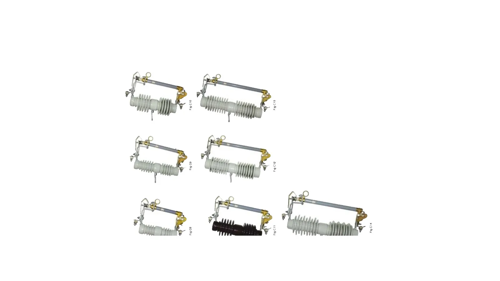
Standard drop out fuse cutout product views on clean white background
FU 01Standard cutout

Standard Drop Out Fuse Cutout

Standard cutout option for overhead distribution protection where fuse tube, upper and lower contacts, insulator body and mounting bracket must be confirmed together.
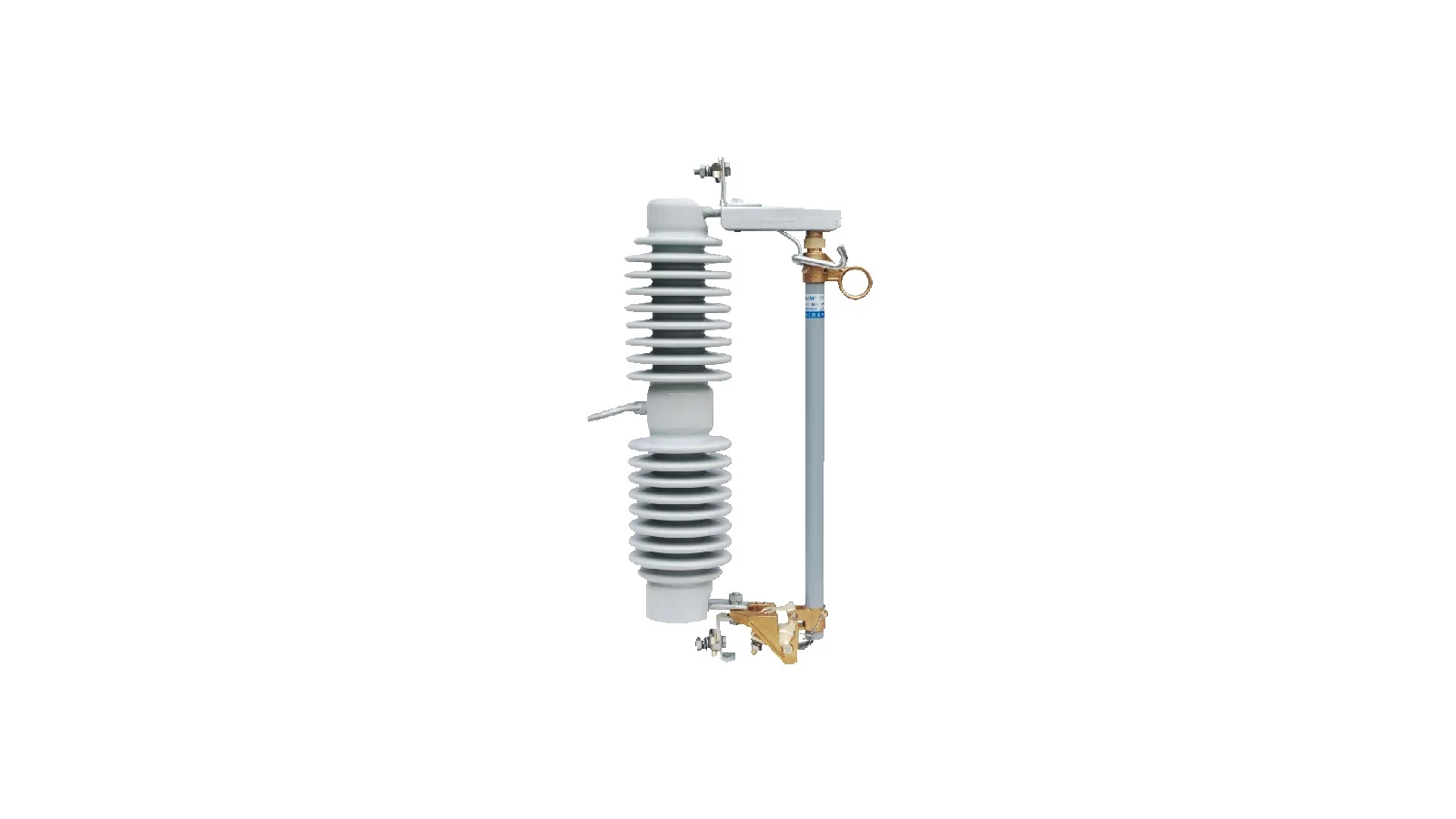
ANSI IEC standard fuse cutout product group on clean white background
FU 02ANSI / IEC

ANSI IEC Standard Fuse Cutout

Standard coordination option for buyers who need the cutout package checked against destination standard and feeder practice.
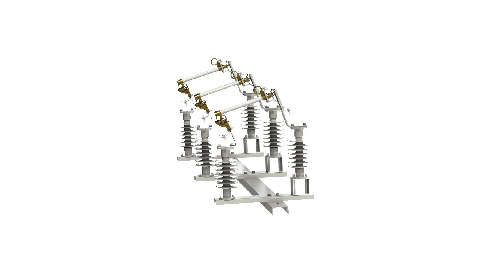
Polymer drop out fuse cutout product pair on clean white background
FU 03Polymer

Polymer Drop Out Fuse Cutout

Silicone or polymer insulation option for outdoor feeders where lighter housing, shed profile and site exposure drive the selection.
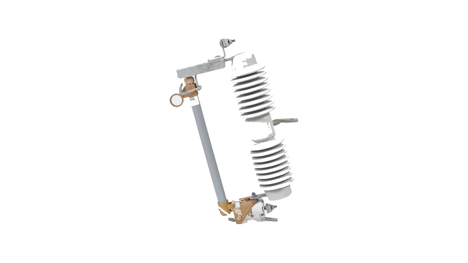
Porcelain drop out fuse cutout product group on clean white background
FU 04Porcelain

Porcelain Drop Out Fuse Cutout

Porcelain insulation option for 12-38 kV RW12 cutouts where the 100A rating row, creepage distance, contact hardware and fuse tube fit are selected together.
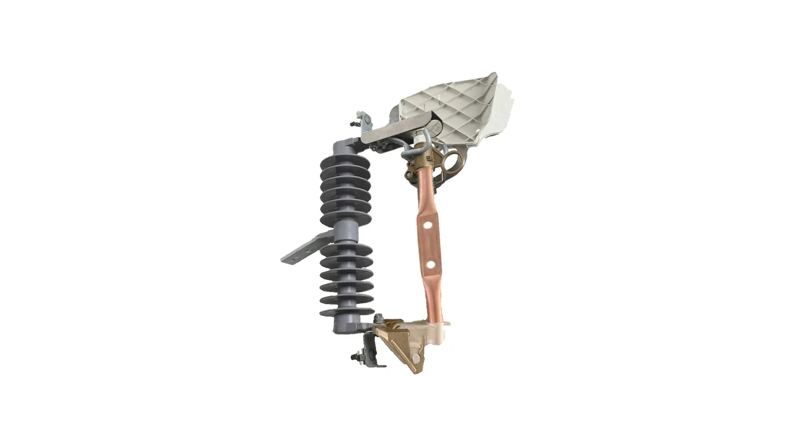
300A expulsion fuse cutout product on clean white background
FU 05300A

300A Expulsion Fuse Cutout

Higher-current Type MZ option where the 300A disconnect rows, BIL class, leakage distance, fuse tube and terminal package must be checked as one package.
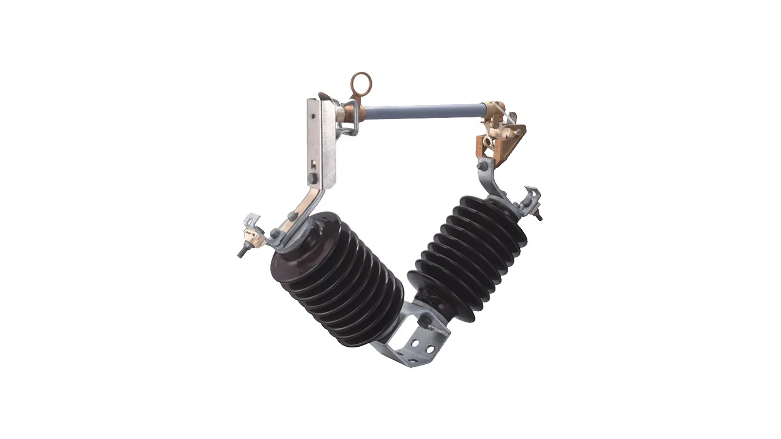
V type drop out fuse bracket accessory package on clean white background
FU 06Bracket

V Type Drop Out Fuse Bracket

Support-hardware package for mounting geometry review; it does not define fuse-link current rating or full cutout voltage class by itself.
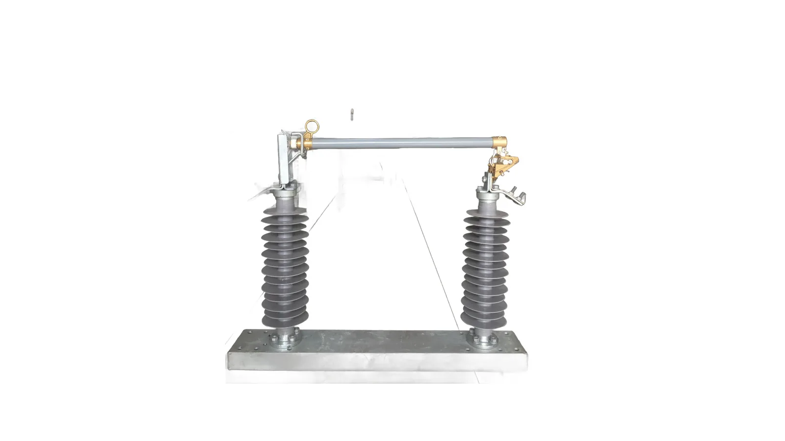
Double column cutout fuse assembly on clean white background
FU 07Double column

Double Column Cutout Fuse

Dual-support option where two insulator columns and base spacing must be confirmed before order release.
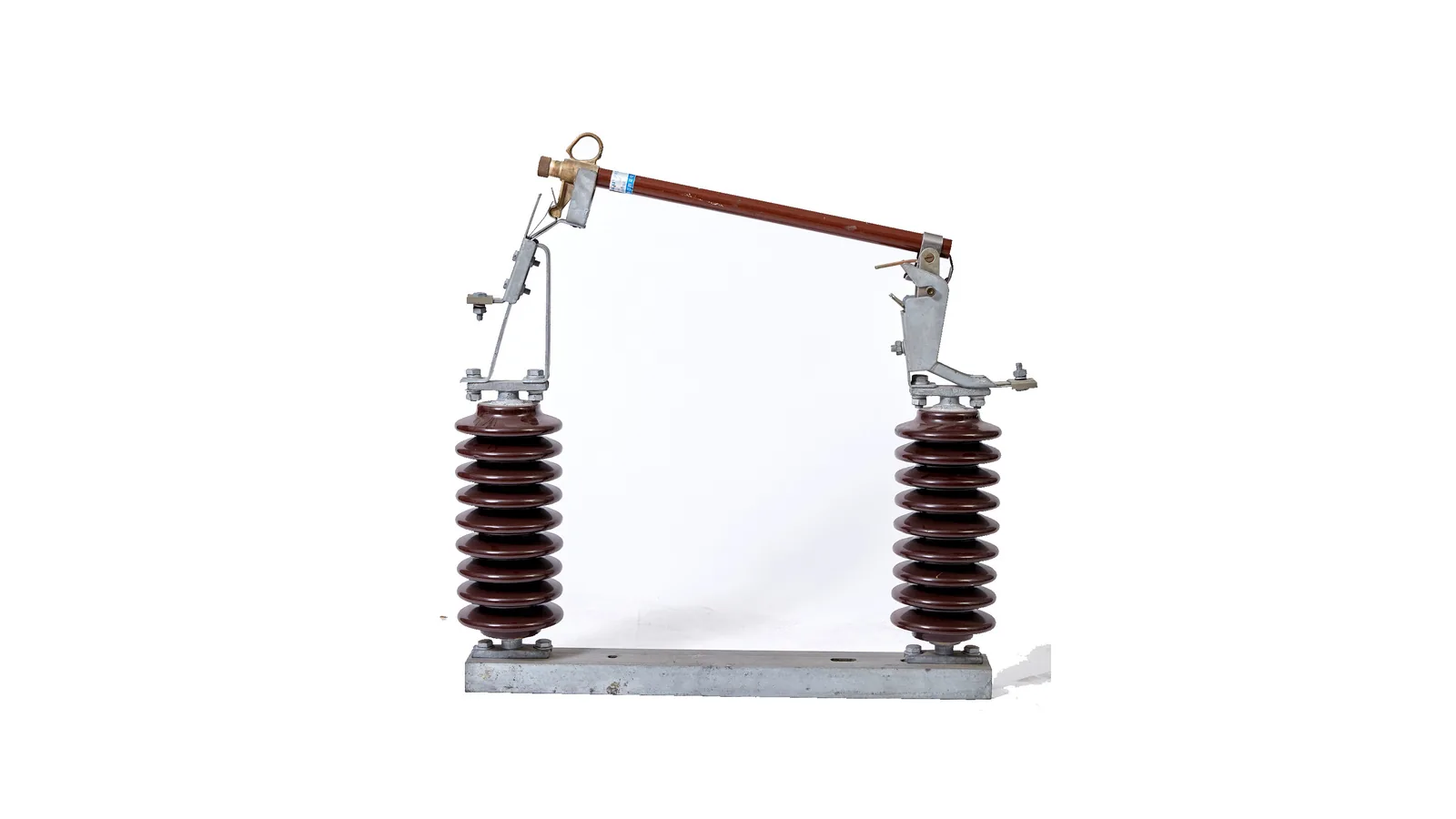
RW5 33kV fuse cutout assembly on clean white background
FU 08RW5

RW5 33kV Fuse Cutout

33 kV pole-mounted protection option where dual insulator support and blade geometry are part of the selection boundary.
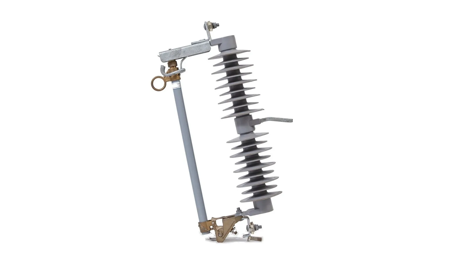
HRW12 12kV to 38kV drop out fuse cutout product view on clean white background
FU 09HRW12

HRW12 12kV to 38kV Drop Out Fuse Cutout

Multi-voltage selection option where the 100A Rw12 rows and 200A HRW12 rows must stay separate from each other before mounting and fuse-link selection.
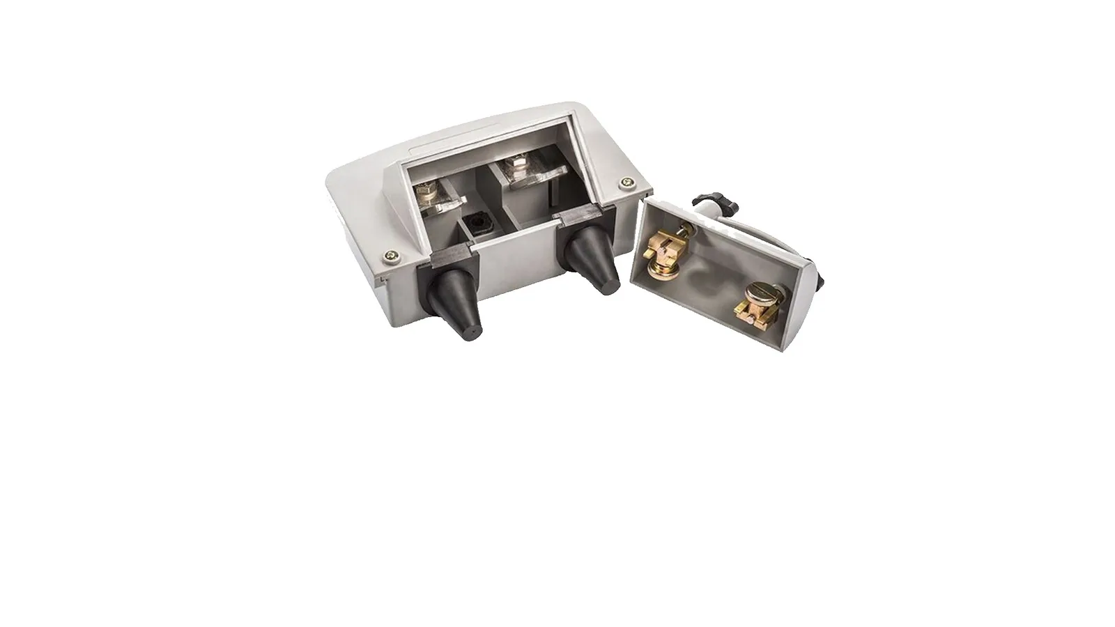
400A pole mounted fuse cutout enclosed product views
FU 10400A

400A Pole Mounted Fuse Cutout

Pole-mounted low-voltage option where the 400A J-type fuse-link package, enclosure material, terminal range and IP43 design target must be checked together.
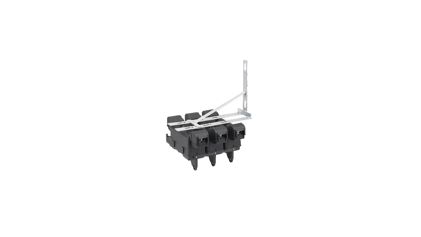
Pole mounted NT fuse switch disconnector product on clean white background
FU 11NT switch

Pole Mounted NT Fuse Switch Disconnector

Low-voltage pole-mounted switch-disconnector option where NH fuse size, FSD body size, operation mode, terminals and indicator option must be selected together.
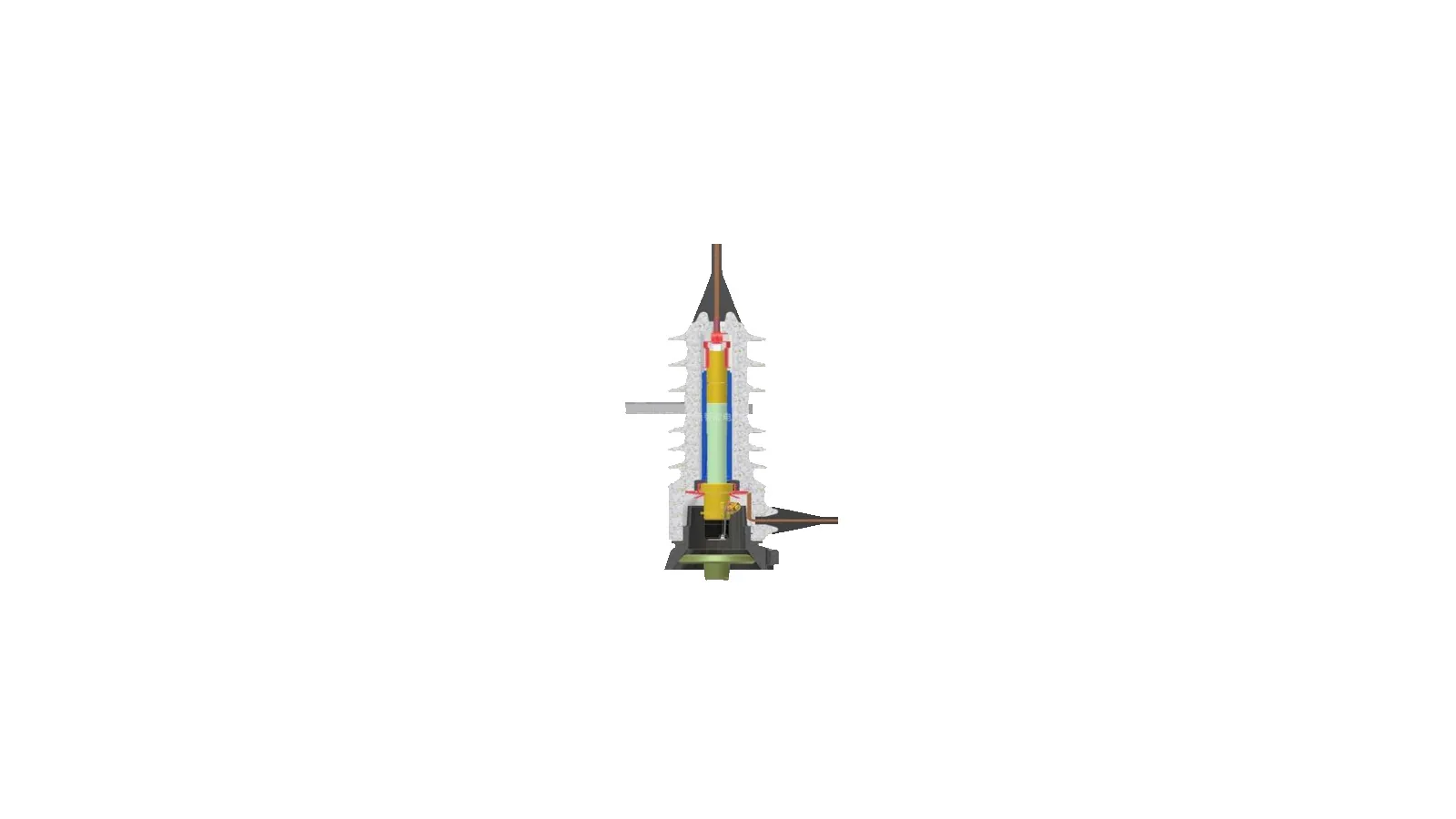
Protected cut out fuse product on clean white background
FU 12Protected

Protected Cut Out Fuse

Sealed protected 12 kV cutout option for harsh outdoor feeders where all-insulated construction, 50A duty, 6-50A fuse range and pollution resistance are the selection basis.
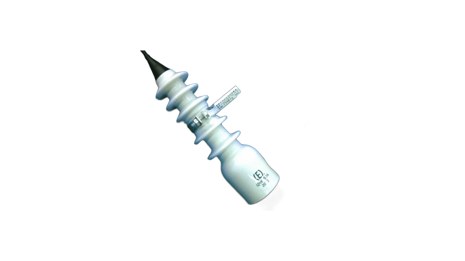
Outdoor enclosed expulsion fuse cutout product view
FU 13Enclosed

Outdoor Enclosed Expulsion Fuse Cutout

Outdoor enclosed expulsion option for 12 kV, 50A protection where PRW 6-50A fuse range, 12.5 kA breaking duty and enclosed body behavior must stay together.
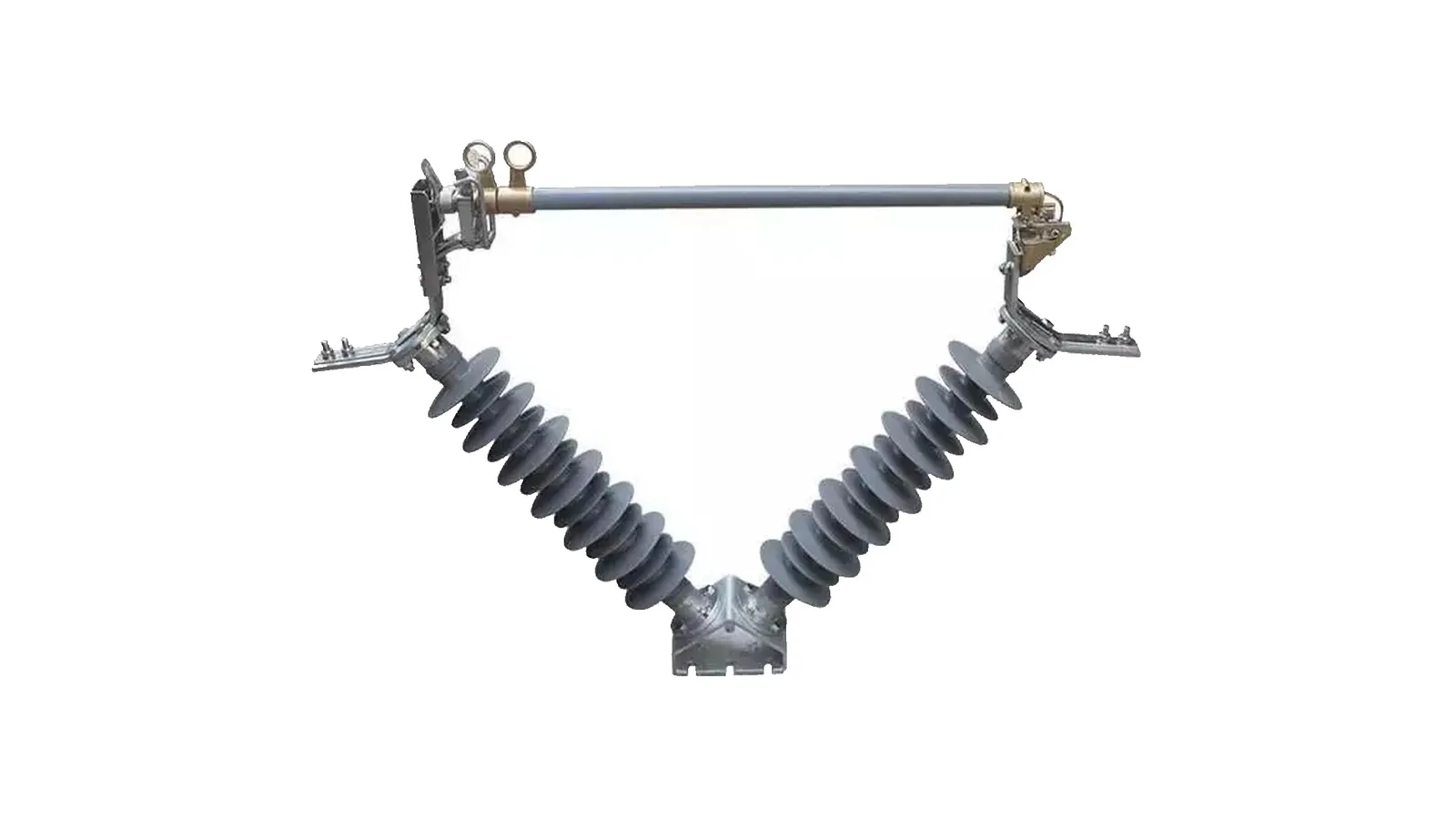
Windproof fuse cutout V shaped product on clean white background
FU 14Windproof

Windproof Fuse Cutout

High-wind outdoor installation option where 40.5 kV voltage duty, 100/200A operating current rows, wind condition and the available dimension view must stay linked.
Technical parameters

Standard Drop Out Fuse Cutout selection boundary

Standard cutout option for overhead distribution protection where fuse tube, upper and lower contacts, insulator body and mounting bracket must be confirmed together.

Reference basisTechnical PDF review, CTF-A and CTF-B rating row review and processed bracket dimension views
Standard drop out fuse cutout product views on clean white background
Standard Drop Out Fuse Cutout clean product image
Product type
standard drop out fuse cutout
Selection option
Main cutout option under Drop Out Fuses
Application point
Overhead feeder branch, transformer tee-off, pole-mounted protection point or service tap
Reference basis
Technical PDF review, CTF-A and CTF-B rating row review and processed bracket dimension views
Drawing availability
Published dimension view available for CTF-A and CTF-B mounting bracket checks
Model row
CTF-A and CTF-B technical rows reviewed
Voltage rows
10-15, 15-27, 24-27, 27-33, 33-36 and 36-38 kV rows
Current rows
100A and 200A rows are separated by voltage class
Interruption rows
10/12 kA at 10-15 and 15-27 kV, 8/10 kA at 24-27 kV and 6.3/8 kA at 27-38 kV
Insulation rows
BIL 110, 125, 150, 170 and 180 kV with creepage from 250 mm to 800 mm by row
Main components
fuse tube, upper and lower contacts, insulator body, pull ring and mounting bracket
Protection role
Fuse-link operation isolates a faulted branch after the fuse element melts
Interface boundary
Confirm bracket, insulator material, terminal hardware and pole mounting option
What to confirm
Confirm voltage class, current row, breaking duty, fuse-link type, bracket and quantity
RFQ checks
Send feeder voltage, transformer or branch duty, fuse-link range, mounting angle, destination standard and quantity

Standard Drop Out Fuse Cutout selection rows

Rating fieldAvailable rating dataSelection note
CTF-A / CTF-B option10-15 through 36-38 kV with 100A and 200A current rowsSelect the exact voltage/current row before quotation
Interrupting capacity100A/200A paired rows: 10/12 kA, 8/10 kA or 6.3/8 kA by voltage classDo not use one interrupting row across every voltage
Withstand and creepageBIL 110-180 kV and creepage 250-800 mm by rowKeep insulation level tied to selected voltage class
Mounting dimensionsCTF-A and CTF-B NEMA Type B bracket views availableUse the published dimension view when bracket fit matters
Selection note

Use the selected option for early model matching. If a value is not listed, confirm it from the project sheet before quotation.

CTF-A and CTF-B NEMA Type B mounting bracket dimension views are available for mounting checks.
Technical parameters

ANSI IEC Standard Fuse Cutout selection boundary

Standard coordination option for buyers who need the cutout package checked against destination standard and feeder practice.

Reference basisClean product image review, rating table review and technical document review
ANSI IEC standard fuse cutout product group on clean white background
ANSI IEC Standard Fuse Cutout clean product image
Product type
ANSI and IEC standard fuse cutout
Selection option
Standard coordination option under Drop Out Fuses
Application point
Overhead distribution feeder protection where ANSI or IEC practice must be stated in the RFQ
Reference basis
Clean product image review, rating table review and technical document review
Drawing availability
Request outline dimensions when fixed mounting fit matters
Structure option
porcelain or polymer insulator body with fuse tube, contact set, pull ring and bracket hardware
Standard boundary
Confirm whether the order follows ANSI cutout practice, IEC cutout practice or a buyer-defined hybrid
Rating boundary
Voltage class, rated current, interrupting duty and fuse-link row must be confirmed together
What to confirm
Confirm standard option, insulation body, fuse tube, bracket, terminal and fuse-link compatibility
RFQ checks
Send destination standard, feeder voltage, current row, breaking duty, fuse-link range, bracket and quantity

ANSI IEC Standard Fuse Cutout selection rows

Decision optionAvailable rating dataSelection note
ANSI optionUse when project documents call for ANSI cutout conventionConfirm hardware and fuse-link compatibility
IEC optionUse when project documents call for IEC cutout conventionConfirm voltage and breaking row
Insulation rowPorcelain and polymer product photos are presentConfirm final insulation body
Drawing rowRequest outline dimensions when fixed mounting fit mattersRequest before fixed-dimension release
Selection note

Use the selected option for early model matching. If a value is not listed, confirm it from the project sheet before quotation.

Technical parameters

Polymer Drop Out Fuse Cutout selection boundary

Silicone or polymer insulation option for outdoor feeders where lighter housing, shed profile and site exposure drive the selection.

Reference basisClean product image review and technical data review
Polymer drop out fuse cutout product pair on clean white background
Polymer Drop Out Fuse Cutout clean product image
Product type
polymer drop out fuse cutout
Selection option
Silicone or polymer insulation option under Drop Out Fuses
Application point
Outdoor distribution feeder, transformer branch or tap protection point
Reference basis
Clean product image review and technical data review
Drawing availability
Request outline dimensions when fixed mounting fit matters
Insulation body
silicone or polymer sheds over an insulated core
Protection role
Fuse tube drops open after fuse-link operation to provide visible open indication
Rating boundary
Do not reuse porcelain housing rows without confirming creepage distance and mechanical fit
What to confirm
Confirm voltage class, creepage distance, housing material, bracket, fuse tube and fuse-link row
RFQ checks
Send system voltage, site exposure, pollution level, current row, breaking duty, fuse-link range and quantity

Polymer Drop Out Fuse Cutout selection rows

Selection fieldAvailable rating dataSelection note
Selection optionPolymer drop out fuse cutoutUse for polymer insulation option
Housing rowPolymer shed product photos confirmedConfirm creepage and exposure
Rating rowProject sheet required for exact voltage and breaking dataDo not infer from image only
Drawing rowRequest outline dimensions when fixed mounting fit mattersRequest before fixed-dimension release
Selection note

Use the selected option for early model matching. If a value is not listed, confirm it from the project sheet before quotation.

Technical parameters

Porcelain Drop Out Fuse Cutout selection boundary

Porcelain insulation option for 12-38 kV RW12 cutouts where the 100A rating row, creepage distance, contact hardware and fuse tube fit are selected together.

Reference basisClean product image review, RW12 100A rating rows and NEMA Type B bracket dimension review
Porcelain drop out fuse cutout product group on clean white background
Porcelain Drop Out Fuse Cutout clean product image
Product type
porcelain drop out fuse cutout
Selection option
Porcelain insulation option under Drop Out Fuses
Application point
Overhead feeder branch, transformer branch or utility distribution pole protection point
Reference basis
Clean product image review, RW12 100A rating rows and NEMA Type B bracket dimension review
Drawing availability
Published dimension view available for RW12 and RW mounting bracket rows
Model boundary
RW12 12-38 kV, 100A porcelain option
Operating conditions
Altitude no more than 2000 m and ambient temperature -40 C to 45 C
Restricted sites
Do not use for flammable or explosive sites, severe vibration or impact, or severe air pollution without project review
Insulation body
porcelain shed body with metal contact set and fuse tube
Voltage and current rows
12, 15, 27, 33, 36 and 38 kV rows with 100A rated current
Breaking rows
10 kA at 12/15 kV, 8 kA at 27 kV and 6.3 kA at 33/36/38 kV
Insulation rows
BIL 110-180 kV, power frequency withstand 40-75 kV and creepage 250-800 mm by voltage row
What to confirm
Confirm voltage class, porcelain body, current row, breaking duty, bracket and fuse-link type
RFQ checks
Send voltage, rated current, breaking current, creepage distance, bracket fit, fuse-link row and quantity

Porcelain Drop Out Fuse Cutout selection rows

VoltageCurrentBreaking currentBILPower withstandCreepageWeight
38 kV100A6300 A180 kV75 kV800 mm16.0 kg
36 kV100A6300 A170 kV72 kV700 mm14.0 kg
33 kV100A6300 A170 kV70 kV700 mm13.5 kg
27 kV100A8000 A150 kV65 kV530 mm10.0 kg
15 kV100A10000 A125 kV45 kV350 mm9.0 kg
12 kV100A10000 A110 kV40 kV250 mm7.0 kg
Selection note

Use the selected option for early model matching. If a value is not listed, confirm it from the project sheet before quotation.

RW12 and RW porcelain cutout mounting bracket dimension rows are available for 10-15 kV through 36-38 kV classes.
Technical parameters

300A Expulsion Fuse Cutout selection boundary

Higher-current Type MZ option where the 300A disconnect rows, BIL class, leakage distance, fuse tube and terminal package must be checked as one package.

Reference basisProduct image review, Type MZ 300A disconnect rows and dimension drawing review
300A expulsion fuse cutout product on clean white background
300A Expulsion Fuse Cutout clean product image
Product type
300A expulsion fuse cutout
Selection option
300A current path under Drop Out Fuses
Application point
Pole-mounted branch or transformer protection point requiring a 300A current path
Reference basis
Product image review, Type MZ 300A disconnect rows and dimension drawing review
Drawing availability
Published dimension view available for Type MZ dimensions and withdrawal angle checks
Current row
300A disconnect rows reviewed separately from the 100A and 200A fuse rows in the same document
Voltage classes
13.8-15 kV, 15-25 kV and 25-34.5 kV classes appear in the 300A disconnect table
BIL rows
110, 125, 150 and 170 kV BIL rows
Momentary asymmetrical duty
16000 A at 110 kV BIL and 12000 A on the other 300A rows
Leakage distance
8.75 in, 12.5 in, 17 in and 26 in rows with metric equivalents
Fuse-link note
Uses removable buttonhead fuse links only
What to confirm
Confirm 300A current row, voltage class, breaking duty, fuse tube and terminal hardware
RFQ checks
Send voltage, current, breaking current, fuse-link range, terminal option, bracket and quantity

300A Expulsion Fuse Cutout selection rows

Voltage classBILContinuous currentMomentary asym.Leakage distance
13.8-15 kV110 kV300A16000 A8.75 in / 225 mm
15-25 kV125 kV300A12000 A12.5 in / 320 mm
15-25 kV150 kV300A12000 A17 in / 432 mm
25-34.5 kV150 kV300A12000 A17 in / 432 mm
25-34.5 kV170 kV300A12000 A26 in / 660 mm
Selection note

Use the selected option for early model matching. If a value is not listed, confirm it from the project sheet before quotation.

Type MZ dimension view includes BIL-based A/B/C/D/E dimensions, net weight and withdrawal angle notes.
Technical parameters

V Type Drop Out Fuse Bracket selection boundary

Support-hardware package for mounting geometry review; it does not define fuse-link current rating or full cutout voltage class by itself.

Reference basisAccessory image review and product document review
V type drop out fuse bracket accessory package on clean white background
V Type Drop Out Fuse Bracket clean product image
Product type
V type drop out fuse bracket
Selection option
Accessory bracket option under Drop Out Fuses
Application point
Pole or crossarm mounting point where a V-type support package is required
Reference basis
Accessory image review and product document review
Drawing availability
Request bracket dimensions when mounting pitch matters
Accessory boundary
This is a mounting and support package, not the full cutout rating package
Fuse-link boundary
does not define fuse-link current rating
Voltage boundary
Confirm selected cutout body separately before assigning voltage class
What to confirm
Confirm bracket shape, mounting hole, phase arrangement, hardware, cutout body and quantity
RFQ checks
Send pole layout, bracket type, mounting pitch, cutout model, hardware need and quantity

V Type Drop Out Fuse Bracket selection rows

Selection fieldAvailable rating dataSelection note
Selection optionV type drop out fuse bracketAccessory bracket package
Application pointPole or crossarm supportConfirm with cutout body
Boundary rowDoes not define fuse-link current ratingUse only as accessory package
Drawing rowRequest bracket dimensions when mounting pitch mattersRequest before fixed-dimension release
Selection note

Use the selected option for early model matching. If a value is not listed, confirm it from the project sheet before quotation.

Technical parameters

Double Column Cutout Fuse selection boundary

Dual-support option where two insulator columns and base spacing must be confirmed before order release.

Reference basisProduct image review and product document review
Double column cutout fuse assembly on clean white background
Double Column Cutout Fuse clean product image
Product type
double column cutout fuse
Selection option
Double-column support option under Drop Out Fuses
Application point
Special pole or base-mounted cutout arrangement requiring dual support columns
Reference basis
Product image review and product document review
Drawing availability
Request outline dimensions when base spacing or terminal position matters
Structure option
two insulator columns with base plate and contact path
Mounting boundary
Base spacing and terminal position must be confirmed by project sheet
Rating boundary
Do not reuse single-column cutout rows without checking contact and support duty
What to confirm
Confirm voltage class, column spacing, base plate, current row, breaking duty and hardware
RFQ checks
Send layout dimension requirement, voltage, current, breaking duty, base interface, hardware and quantity

Double Column Cutout Fuse selection rows

Selection fieldAvailable rating dataSelection note
Selection optionDouble column cutout fuseDual-support option
Structure rowTwo-column assembly confirmed by product imageConfirm base and terminal fit
Rating rowProject sheet required for exact electrical dutyDo not infer from support count
Drawing rowRequest outline dimensions when base spacing mattersRequest before fixed-dimension release
Selection note

Use the selected option for early model matching. If a value is not listed, confirm it from the project sheet before quotation.

Technical parameters

RW5 33kV Fuse Cutout selection boundary

33 kV pole-mounted protection option where dual insulator support and blade geometry are part of the selection boundary.

Reference basisClean product image review and product document review
RW5 33kV fuse cutout assembly on clean white background
RW5 33kV Fuse Cutout clean product image
Product type
RW5 33kV fuse cutout
Selection option
33 kV RW5 option under Drop Out Fuses
Application point
33 kV overhead distribution line or transformer branch protection point
Reference basis
Clean product image review and product document review
Drawing availability
Request outline dimensions when mounting layout matters
Voltage row
33 kV option identified from selection option
Structure option
dual insulator support with overhead fuse path and base bracket
Boundary note
Confirm whether project needs RW5 or another 33 kV cutout body
What to confirm
Confirm 33 kV requirement, rated current, breaking duty, fuse link and bracket fit
RFQ checks
Send system voltage, current row, breaking duty, mounting layout, fuse-link range and quantity

RW5 33kV Fuse Cutout selection rows

Selection fieldAvailable rating dataSelection note
Selection optionRW5 33kV fuse cutout33 kV option
Voltage row33 kV identified in selection optionConfirm project insulation level
Structure rowDual support assembly confirmed by product imageConfirm bracket and base fit
Drawing rowRequest outline dimensions when mounting layout mattersRequest before fixed-dimension release
Selection note

Use the selected option for early model matching. If a value is not listed, confirm it from the project sheet before quotation.

Technical parameters

HRW12 12kV to 38kV Drop Out Fuse Cutout selection boundary

Multi-voltage selection option where the 100A Rw12 rows and 200A HRW12 rows must stay separate from each other before mounting and fuse-link selection.

Reference basisInstruction sheet review, 100A and 200A rating table review and processed outline dimension view
HRW12 12kV to 38kV drop out fuse cutout product view on clean white background
HRW12 12kV to 38kV Drop Out Fuse Cutout clean product image
Product type
HRW12 12kV to 38kV drop out fuse cutout
Selection option
Multi-voltage HRW12 option under Drop Out Fuses
Application point
Overhead distribution feeder branch or transformer branch protection point
Reference basis
Instruction sheet review, 100A and 200A rating table review and processed outline dimension view
Drawing availability
Published dimension view available for the 200A rating table and 38 kV / 24 kV outline dimensions
100A row
12, 15, 24, 27, 33, 36 and 38 kV rows with 6300 A or 10000 A breaking current
200A row
12, 15, 24, 27, 33, 36 and 38 kV rows with 12500 A breaking current
100A insulation data
BIL 110-170 kV, power frequency withstand 40-72 kV and creepage 250-900 mm by voltage row
Operating conditions
Altitude no more than 2000 m and ambient temperature -40 C to 45 C
Restricted sites
Avoid flammable or explosive sites, severe vibration or impact, and severe air pollution without project review
Structure option
upper contact base, fuse carrier, lower contact base and isolator
What to confirm
Confirm exact voltage row, current row, breaking duty, mounting option and fuse-link type from the same row
RFQ checks
Send voltage, rated current, breaking current, fuse-link range, bracket, outline need and quantity

HRW12 12kV to 38kV Drop Out Fuse Cutout selection rows

Current rowVoltage rowsBreaking dataWeight dataSelection note
100A Rw1212/15/24/27/33/36/38 kV6300 A except 24 kV at 10000 A7.0-16.0 kg by voltage rowUse this row when the order calls for the 100A cutout option
200A HRW1212/15/24/27/33/36/38 kV12500 A across the listed voltage rows8.0-16.0 kg by voltage rowUse this row only with the 200A body and contact package
100A insulation12-38 kVBIL 110-170 kV and power withstand 40-72 kVCreepage 250-900 mmKeep insulation data tied to the 100A table
Outline dimensions38 kV and 24 kV examples shown365 +/-10 and 480 +/-10 mm views appear in the drawingBracket opening 70-100 mm shownUse the published dimension view for mounting review
Selection note

Use the selected option for early model matching. If a value is not listed, confirm it from the project sheet before quotation.

HRW12 drawing view shows the 200A 12-38 kV rating table with 38 kV and 24 kV outline dimensions.
Technical parameters

400A Pole Mounted Fuse Cutout selection boundary

Pole-mounted low-voltage option where the 400A J-type fuse-link package, enclosure material, terminal range and IP43 design target must be checked together.

Reference basisClean product image review, 400A pole-mounted cutout document review and processed enclosure view
400A pole mounted fuse cutout enclosed product views
400A Pole Mounted Fuse Cutout clean product image
Product type
400A pole mounted fuse cutout
Selection option
400An option under Drop Out Fuses
Application point
Pole-mounted protection point requiring an enclosed or protected 400A current path
Reference basis
Clean product image review, 400A pole-mounted cutout document review and processed enclosure view
Drawing availability
Published dimension view available for enclosure and terminal details
Current row
J-type fuse links to BS88 up to 400A with 82 mm fixing centers
Standard and protection
Compliant with BS 7656:1993 and designed to IP43
Housing option
Track-resistant Glass Reinforced Polyester / DMC housing with slide-fit front cover
Stud option
M12 captive studs accept copper or aluminium compression lugs up to 300 mm2
Mechanical terminal option
Shear-head terminals accept aluminium and solid copper conductors from 70 mm2 to 300 mm2
Small conductor adaptor
Adaptor available for 25 mm2 and 35 mm2 copper or aluminium conductors
What to confirm
Confirm 400A current row, voltage class, enclosure type, fuse package and pole mounting
RFQ checks
Send voltage, current, protection duty, housing option, bracket, standard and quantity

400A Pole Mounted Fuse Cutout selection rows

Selection fieldAvailable dataSelection note
Fuse linkStandard wedge J-type fuse links to BS88, 20A to 400A range notedConfirm final J-type rating and coordination requirement
Conductor interfaceM12 studs for lugs up to 300 mm2; shear-head terminal option for 70-300 mm2Confirm cable material and lug option
Mounting interfaceWall, pole or cross-arm mounting option; M12 coach screw noted for wooden pole or wall mountingConfirm project mounting surface
Ingress targetPVC cable sealing grommets with IP43 design targetConfirm outdoor service condition
Selection note

Use the selected option for early model matching. If a value is not listed, confirm it from the project sheet before quotation.

Processed view shows compact enclosure geometry, fuse carrier access and terminal assembly details without using the page header.
Technical parameters

Pole Mounted NT Fuse Switch Disconnector selection boundary

Low-voltage pole-mounted switch-disconnector option where NH fuse size, FSD body size, operation mode, terminals and indicator option must be selected together.

Reference basisClean product image review, FSD dimension table review and NT switch drawing review
Pole mounted NT fuse switch disconnector product on clean white background
Pole Mounted NT Fuse Switch Disconnector clean product image
Product type
NT fuse switch disconnector
Selection option
Pole-mounted switch-disconnector option under Drop Out Fuses
Application point
Pole-mounted fuse switching or disconnection point where NT fuse package is required
Reference basis
Clean product image review, FSD dimension table review and NT switch drawing review
Drawing availability
Published dimension view available for the pole-mounted 400A body
Switching boundary
Fuse switch disconnector function is not the same as open expulsion cutout action
Fuse package boundary
FSD-00 uses NT fuse size 00 up to max 160A, with blade option up to max 250A
FSD-1-2 package
NT fuse size 1 up to max 250A or size 2 up to max 400A, with blade option up to max 630A
Material option
Glassfibre reinforced polyamide body, aluminium-alloy, tinned copper and hot-dip galvanized steel components
Operation option
562 and 566 indicate individual operation; 564 and 568 indicate linked operation
Terminal option
VC1, VI11 and LI13 terminal compositions appear in the numbering system
What to confirm
Confirm NT fuse package, current row, voltage class, terminal, bracket and quantity
RFQ checks
Send fuse size, system voltage, current row, mounting point, operation need and quantity

Pole Mounted NT Fuse Switch Disconnector selection rows

Body optionDimensionsFuse packageSelection note
FSD0C 235 mm, B 65 mm, A 115 mm, E 90 mm, 1.5 kgNT fuse size 00 max 160AUse for smaller low-voltage fuse switch option
FSD-1-2C 300 mm, B 80 mm, A 160 mm, E 200 mm, 2.0 kgNT fuse size 1 max 250A or size 2 max 400AUse for the larger fuse switch option
Disconnecting bladesMax 250A for FSD-00 and max 630A for FSD-1-2Blade option instead of NH fuse insertConfirm switching and protection requirement
IndicatorsInspection glass, yellow mechanical indicator, signal-lamp option or combined optionOptional indication packageConfirm indication requirement before quotation
Selection note

Use the selected option for early model matching. If a value is not listed, confirm it from the project sheet before quotation.

Dimension drawing shows the 400A LV fuse switch body, pole hardware and component list after removing non-technical price text.
Technical parameters

Protected Cut Out Fuse selection boundary

Sealed protected 12 kV cutout option for harsh outdoor feeders where all-insulated construction, 50A duty, 6-50A fuse range and pollution resistance are the selection basis.

Reference basisProduct image review and protected cutout technical document review
Protected cut out fuse product on clean white background
Protected Cut Out Fuse clean product image
Product type
protected cut out fuse
Selection option
Protected cutout option under Drop Out Fuses
Application point
Outdoor feeder or branch point requiring added protection around the cutout body
Reference basis
Product image review and protected cutout technical document review
Drawing availability
Request publish-ready outline when protected housing dimensions are required
Rated voltage and current
12 kV rated voltage and 50A rated current
Fuse current range
6-50A fuse current range
Frequency and breaking
50 Hz rated frequency and 8 kA rated breaking current
Insulation performance
To earth: 42 kV dry, 30 kV wet and 75 kV impulse; across break: 18 kV dry, 36 kV wet and 85 kV impulse
Use conditions
Ambient temperature -30 C to 40 C, altitude no more than 2000 m and wind speed no more than 35 m/s
Construction option
Fully sealed and all-insulated body with molded rubber inlet and outlet leads
Operation indication
Fuse tube pops out and the lower sealing cover drops after interruption
What to confirm
Confirm protected body option, cable path, voltage class, current row and mounting hardware
RFQ checks
Send site condition, feeder voltage, current row, cable path, bracket, dimension requirement and quantity

Protected Cut Out Fuse selection rows

ParameterProtected cutout dataSelection note
Rated voltage12 kVUse only on matching system voltage
Rated current50A with 6-50A fuse current rangeConfirm fuse coordination
Breaking current8 kAConfirm site fault duty
Energized part exposureFully enclosed constructionKeep separate from open drop-out fuse option
Operating methodSpecial fuse-tube operating tool notedConfirm operating tool requirement
Selection note

Use the selected option for early model matching. If a value is not listed, confirm it from the project sheet before quotation.

Technical parameters

Outdoor Enclosed Expulsion Fuse Cutout selection boundary

Outdoor enclosed expulsion option for 12 kV, 50A protection where PRW 6-50A fuse range, 12.5 kA breaking duty and enclosed body behavior must stay together.

Reference basisTechnical PDF review, enclosed expulsion rating table review and cropped product image processing
Outdoor enclosed expulsion fuse cutout product view
Outdoor Enclosed Expulsion Fuse Cutout clean product image
Product type
outdoor enclosed expulsion fuse cutout
Selection option
Enclosed expulsion option under Drop Out Fuses
Application point
Outdoor branch or transformer protection point requiring enclosed fuse body
Reference basis
Technical PDF review, enclosed expulsion rating table review and cropped product image processing
Drawing availability
Request publish-ready outline when enclosure dimensions are required
Model row
PRW-12/(6-50)-12.5 EC-11 row reviewed
Rated voltage and current
12 kV rated voltage and 50A rated current
Breaking and frequency
12.5 kA breaking current and 50/60 Hz frequency
Fuse range
6A, 10A, 15A, 20A, 25A, 30A, 40A and 50A fuse rows
Withstand data
42 kV dry and 30 kV wet to earth; 48 kV dry across break; 75 kV to-earth impulse and 85 kV across-break impulse
Operation tests
300 mechanical operations, 1000A for 1 second once, and 630 kVA transformer no-load current switching 10 times
Pull and weight
200 N no-disengagement pull strength and about 6 kg weight
Housing option
outdoor enclosed body around the fuse path
Expulsion role
expulsion function remains the protection mechanism, but enclosure changes installation boundary
What to confirm
Confirm enclosure option, cable connection, voltage class, current row and mounting method
RFQ checks
Send voltage, current, fault duty, cable or pole interface, enclosure requirement and quantity

Outdoor Enclosed Expulsion Fuse Cutout selection rows

Selection fieldAvailable dataSelection note
ModelPRW-12/(6-50)-12.5 EC-11Confirm final model marking before production
Main duty12 kV, 50A, 12.5 kA, 50/60 HzKeep voltage, current and breaking duty together
Fuse range6-50A with listed 6A to 50A rowsConfirm fuse coordination
Switching checks50A 15 times, 2.5A 15 times and 65A 5 times listed under 12 kV load-current switchingConfirm switching requirement if used beyond fault protection
Outline rowDimension drawings are scanned with non-English labelsRequest publish-ready outline for mounting release
Selection note

Use the selected option for early model matching. If a value is not listed, confirm it from the project sheet before quotation.

Technical parameters

Windproof Fuse Cutout selection boundary

High-wind outdoor installation option where 40.5 kV voltage duty, 100/200A operating current rows, wind condition and the available dimension view must stay linked.

Reference basisProduct image review, windproof technical document review and processed clean dimension drawing view
Windproof fuse cutout V shaped product on clean white background
Windproof Fuse Cutout clean product image
Product type
windproof fuse cutout
Selection option
Windproof cutout option under Drop Out Fuses
Application point
Outdoor pole-mounted cutout option where wind action and stable drop-out behavior must be reviewed
Reference basis
Product image review, windproof technical document review and processed clean dimension drawing view
Drawing availability
Published dimension view available because a clean cropped dimension drawing is confirmed
Model row
HRW12-35 kV, HGRW-35/200 and HGRW1-40.5/200A rows appear in the available documents
Voltage row
40.5 kV rated voltage row reviewed
Current row
100A and 200A rated working current rows reviewed
Dynamic stability
80 kA and 120 kA peak rows reviewed
Thermal stability
6.3 kA and 16 kA peak rows with 4 second thermal stability time reviewed
Use conditions
Ambient temperature -45 C to 55 C, altitude no more than 3000 m, wind speed no more than 50 m/s and seismic intensity no more than 8
Material option
Silicone rubber insulation, pultruded rod core, T2 copper contact material and stainless standard fasteners noted
Dimension row
1100 +/-5 and 590 +/-5 dimensions appear in the cropped drawing view
What to confirm
Confirm windproof option, voltage class, current row, breaking duty, bracket and dimension requirement
RFQ checks
Send system voltage, current row, breaking duty, wind condition, bracket, drawing confirmation and quantity

Windproof Fuse Cutout selection rows

Model rowAvailable rating dataSelection note
HRW12-35 kV / HGRW-35/200Windproof option for high-wind serviceConfirm final factory model before production
Rated voltage40.5 kVConfirm project voltage
Rated working current100A / 200ASelect the matching current row
Stability rowsDynamic 80/120 kA peak and thermal 6.3/16 kA peak for 4 secondsConfirm fault-duty requirement
Drawing rowClean cropped dimension view processedPublished dimension view available
Selection note

Use the selected option for early model matching. If a value is not listed, confirm it from the project sheet before quotation.

clean cropped dimension drawing confirmed from the right-side engineering view.
Technical parameters

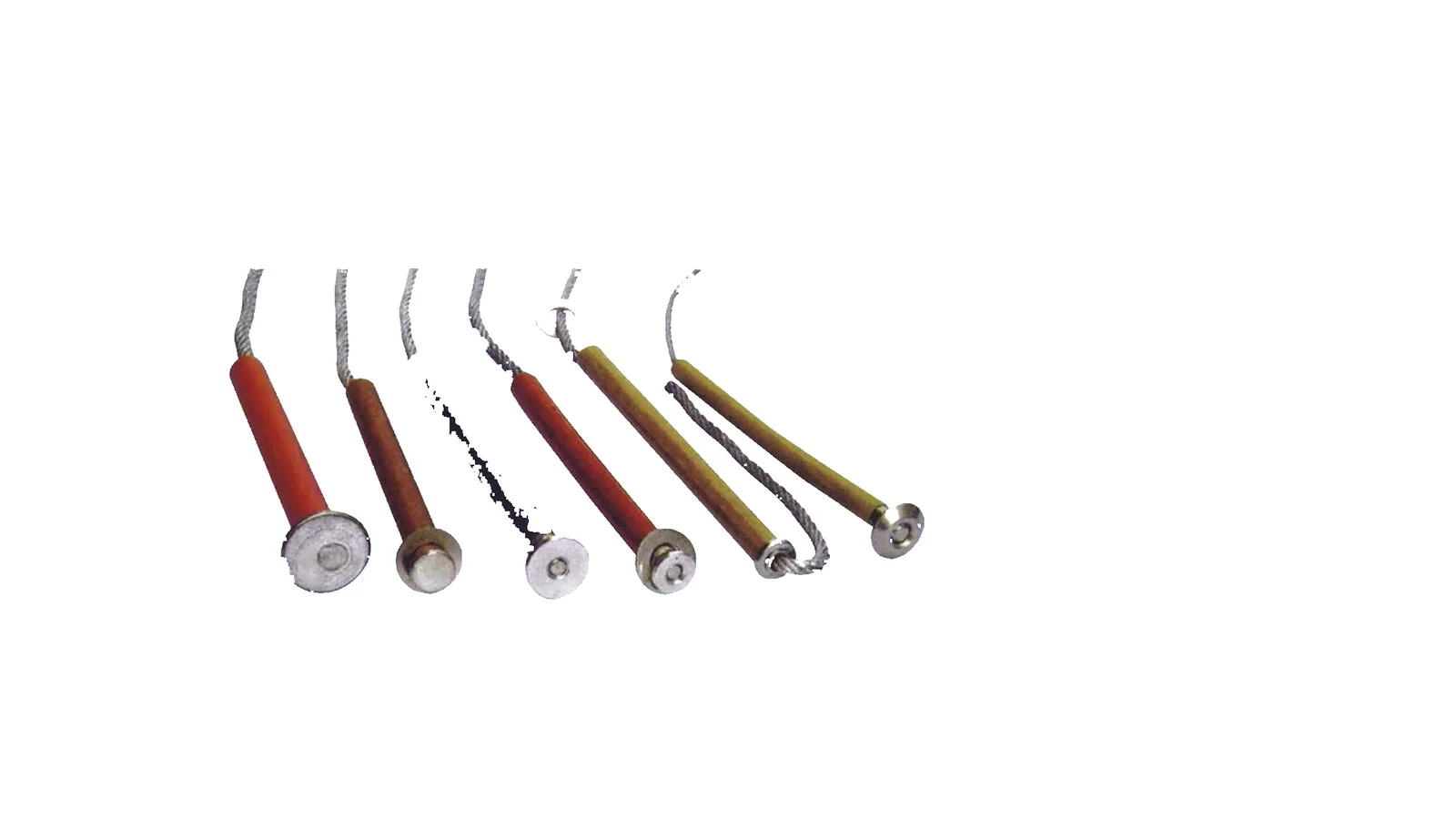
Accessory fuse-link package for K/T fuse element selection, current range and button or screw-thread construction; it does not define cutout voltage class by itself.

Reference basisAccessory technical document review and cropped fuse-link image processing
Fuse link accessories for drop out fuse cutout on clean white background
Fuse Link for Drop Out Fuse Cutout clean product image
Product type
fuse link for drop out fuse cutout
Selection option
Accessory fuse-link option under Drop Out Fuses
Application point
Fuse element package used inside a compatible drop out fuse cutout
Reference basis
Accessory technical document review and cropped fuse-link image processing
Drawing availability
Published drawing view available for fuse-link outline dimensions and K/T curve reference
Accessory boundary
does not define cutout voltage class
Fuse-link type
K and T fuse-link option with general, universal and screw-thread forms
Standard option
IEC 282 option noted in the fuse-link document
Voltage application
11-36 kV grade drop-out fuse applications
Construction elements
flexible rope, arc-extinguishing tube, washer when needed, button or M6x11 screw thread
Current ranges
1-25A, 30-40A, 50-100A and 140-200A dimension rows
Current boundary
Fuse-link current row must match the selected cutout and protection coordination
Compatibility boundary
Confirm button, rope, screw thread, arc-extinguishing tube and compatible cutout body before release
What to confirm
Confirm fuse-link type, rated current, compatible cutout model, standard and quantity
RFQ checks
Send cutout model, voltage class, fuse-link current, fuse-link type, coordination requirement and quantity

Fuse Link for Drop Out Fuse Cutout selection rows

Current rangeA / B dimensionsD / E dimensionsCarton quantity
1-25AA 12.5 +/-0.2, B 19.0 +/-0.2D 2.0, E 6.5500
30-40AC dimension per construction noteD 3.0, E 8.0500
50-100AA 19.0 +/-0.3, B not applicableD 5.0, E 10.0250
140-200AA row follows the high-current construction, B not applicableD 7.0, E 12.0150
Selection note

Use the selected option for early model matching. If a value is not listed, confirm it from the project sheet before quotation.

Fuse-link drawing view shows button and screw-thread outline dimensions plus K/T curve reference views.
Application fit

Drop Out Fuse Applications

The first decision is the installation role: feeder branch, transformer tap, service point, protected enclosure, windproof outdoor point or accessory replacement.

Protection role

Drop out fuse duty is selected by where the fuse must isolate a branch.

Separate the cutout body from fuse-link coordination and mounting accessories before comparing voltage or breaking rows.

Feeder branch

Standard, ANSI IEC, polymer and porcelain cutout bodies

Use these options when the main pole-mounted cutout body carries the protection duty.

Current row

300A and 400A cutout packages

Use these options when the current path and contact package are the first selection constraint.

Protected body

Protected, enclosed and windproof installation conditions

Use these options when enclosure, wind action, cable path or site protection changes the cutout body.

Hardware package

Support hardware and fuse-link package after body selection

Confirm these options after the compatible cutout body is known.

Selection matrix

Drop Out Fuse Selection Matrix

Choose the product type first, then check the matching rating row, mounting boundary and document requirement.

Decision option
What to confirm
Selection boundary
Standard / ANSI IECStandard cutout body
Destination standard, feeder voltage, current row and fuse-link compatibility
Use when the order follows a standard pole cutout body and the destination standard drives hardware choice.
Polymer / porcelainInsulation body option
Housing material, creepage distance, shed profile and site exposure
Keep insulation material, creepage and mechanical fit tied to the selected body option.
300A / 400AHigher-current option
Contact package, fuse tube, voltage class and breaking duty
Confirm contact package and fuse tube before assigning the higher-current row.
Protected / enclosedGuarded or enclosed body option
Housing, cable entry, service condition and access requirement
Use when enclosure, cable path or guarded access changes the cutout package.
WindproofHigh-wind cutout option
HGRW model, 40.5 kV, 200A, 12.5 kA and dimension drawing
Use the available dimension view for mounting checks and keep HGRW data with this option.
Bracket / fuse linkAccessory option
Cutout body compatibility before accessory current or mounting release
Accessory rows do not define full cutout voltage, current or interruption duty.
Working principle

Drop Out Fuse Operation

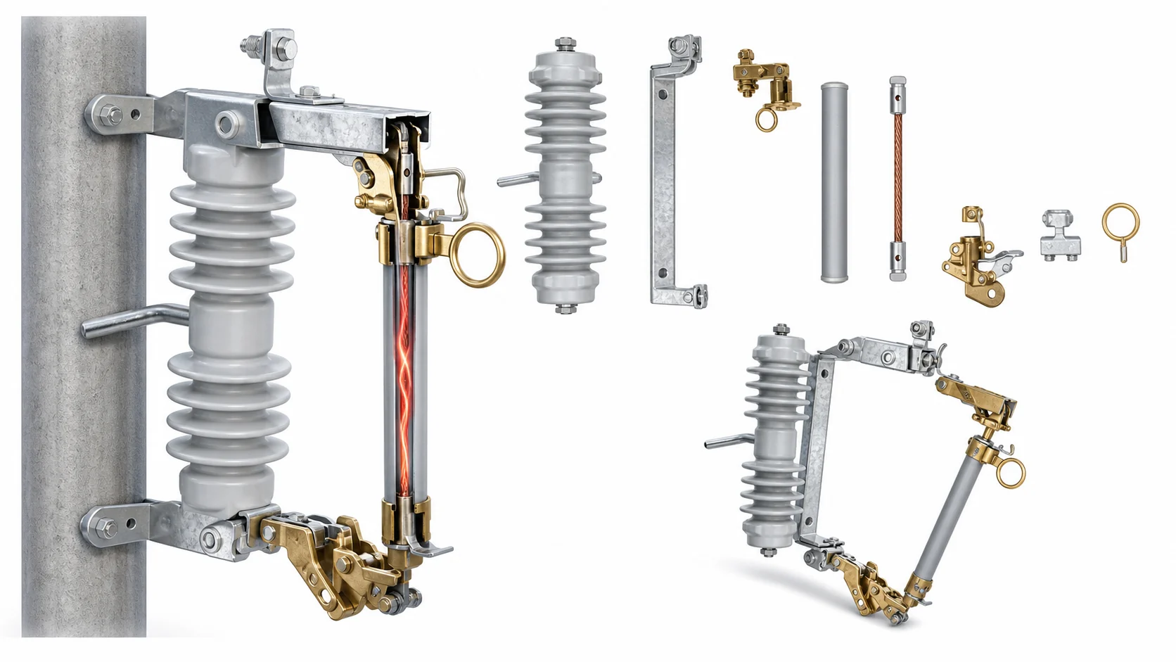
A drop out fuse cutout combines an insulator body, upper contact, lower hinge, fuse tube and pull ring. When the fuse element melts, the tube releases and drops open to show the protected branch is isolated.

Operating checks before release

Confirm the load path, fuse action and mounting interface as one package.

Contact pathUpper and lower contacts carry normal current and must match the selected current row.
Fuse tube actionThe fuse tube supports the fuse link and drops open after operation.
Arc pathExpulsion action and fuse-link coordination decide the protection package.
Bracket interfacePole hardware, V bracket, enclosure or protected body decides mounting fit.
Rating boundary

Drop Out Fuse Ratings

This category includes full cutout bodies and accessory packages. Do not assign voltage class, current row or breaking duty from an accessory image alone.

Cutout body

Voltage, current and breaking rows belong to the selected cutout body.

Standard, ANSI IEC, polymer, porcelain, expulsion, protected, enclosed and windproof options require separate model confirmation.

Accessory package

Accessory data supports fit and coordination only.

Use bracket data for mounting geometry and fuse-link data for protection coordination after the cutout body is known.

Voltage row12 kV to 40.5 kV options require row match

Do not merge RW5, HRW12, porcelain, polymer and windproof values.

Current row200A, 300A and 400A rows stay separate

Use the contact package and fuse tube configuration before selecting the current row.

Breaking row6.3 kA, 10 kA and 12.5 kA rows must stay separated

Confirm fault duty from the matching rating row before quotation.

Accessory packageAccessory data supports selection only

It does not set voltage class or complete cutout duty.

Document review

Drop Out Fuse Drawings

Use product images for configuration recognition, technical documents for listed values, and drawing views only when dimensions support mounting or fuse-link checks; teams can also download drop-out fuse catalog PDFs before final model review.
Windproof fuse cutout V shaped product on clean white background
Windproof cutout product identity
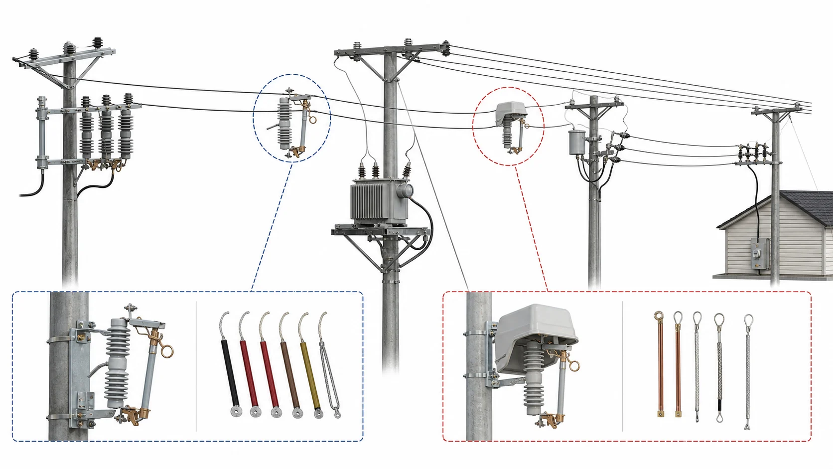
Engineering topology image showing drop out fuse cutouts on overhead distribution feeder and transformer branch options
Drop out fuse placement by system role
Engineering structure image showing fuse tube contacts bracket arc path and drop out action
Fuse tube, contact and drop-out action logic
Product identity

Match the visible configuration

Use product photos to distinguish cutout body, enclosure, bracket and fuse-link forms; do not assign ratings from appearance alone.

SPEC boundary

Keep values document-backed

Photo-only or accessory options do not receive invented voltage, current or breaking rows.

Drawing boundary

Use drawings for dimensions, not ratings

Dimension or curve views support mounting, terminal and fuse-link checks; unavailable views should become an outline request.

Model row

Keep model rows tied to their tables

RW5, HRW12, HGRW, NT and fuse-link rows must stay with their own voltage, current and construction data.

Engineering selection

Drop Out Fuse RFQ Data

Confirm product type, duty, mounting and document requirements in that order so quotation data stays tied to the selected body, or check certificates, test reports and RFQ forms when project files need review.

01 / TypeSelect the product type

Standard, ANSI IEC, polymer, porcelain, expulsion, windproof, protected, enclosed, bracket or fuse-link option.

02 / DutyMatch protection duty

System voltage, rated current, breaking duty and fuse-link coordination.

03 / FitConfirm mounting interface

Pole, crossarm, bracket, V-type support, enclosure or protected cable path.

04 / DocumentsRequest dimension evidence

Use the published drawing view for fixed interfaces or ask XIYA to return an outline.

Product typeSelected cutout body, accessory or fuse-link option.
System voltageNominal voltage, insulation level, destination standard and outdoor exposure.
Rated currentCutout current row or fuse-link current range, kept separate by product type.
Breaking dutyFault current or interruption duty required at the installation point.
Fuse packageFuse tube, fuse-link type, speed, button, rope, thread or arc-extinguishing tube detail.
Mounting interfacePole, crossarm, bracket, V-type support, enclosed body or protected cable path.
Dimension requirementPublished view, outline drawing request or curve reference required for the selected option.
QuantityQuantity by phase, product type, spare requirement and destination standard.
FAQ

Drop Out Fuse FAQ

What is a drop out fuse used for?

It protects an overhead distribution branch, transformer tap or feeder section by opening the fuse tube after the fuse element operates.

When should drawing information be used for drop out fuses?

Use drawing information for bracket fit, enclosure space, terminal position, fuse-link dimensions and curve checks. If an option does not provide a usable drawing view, include an outline request with the RFQ.

Can a bracket or fuse link define the full cutout rating?

No. They support mounting or fuse-element coordination only. The selected cutout body sets voltage class, current row and breaking duty.

How should protected, enclosed and windproof cutouts be separated?

Use protected or enclosed options when guarded access, cable entry or service enclosure drives the body choice. Use windproof options when wind action and stable drop-out behavior are the main fit questions.

Request Drop Out Fuse Quote

Send the selected product type, rating row, protection duty and any fixed mounting dimensions. XIYA will confirm the matching cutout body, accessory compatibility, dimension requirement and document list.

Send Project Details
