Quotation form
Send an inquiry
Start with the basics. Our team can follow up for missing drawings, standards or packing details.
Submitted details are used only for quotation, technical review and project communication.
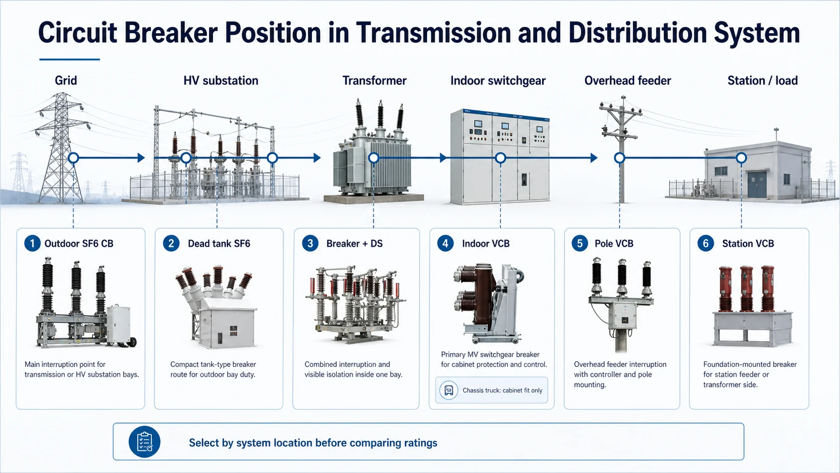
Use this selector to separate outdoor SF6, dead tank SF6, combined breaker-disconnector, indoor VCB, side-mounted VCB, ZN85, pole-mounted VCB, station VCB and chassis truck accessory paths before confirming ratings and drawings.
This category works as one direct selector. Each product detail keeps its own ratings, Drawing status and RFQ boundary.
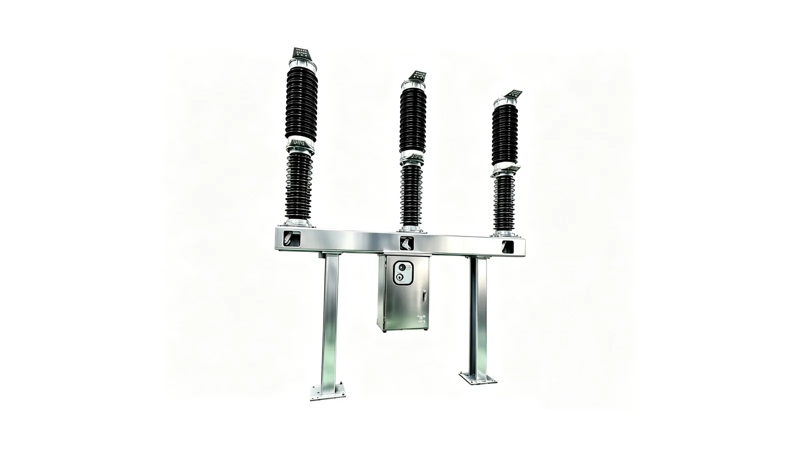
High-voltage outdoor SF6 breaker path for substation bays where LW36A/B-72.5/126/145 and LWD-126 rating data must be checked separately.
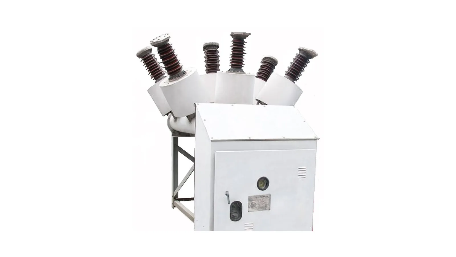
Tank-type SF6 breaker path for compact outdoor bay applications where the rating document lists LW24-40.5(72.5) and CT20-II mechanism data.
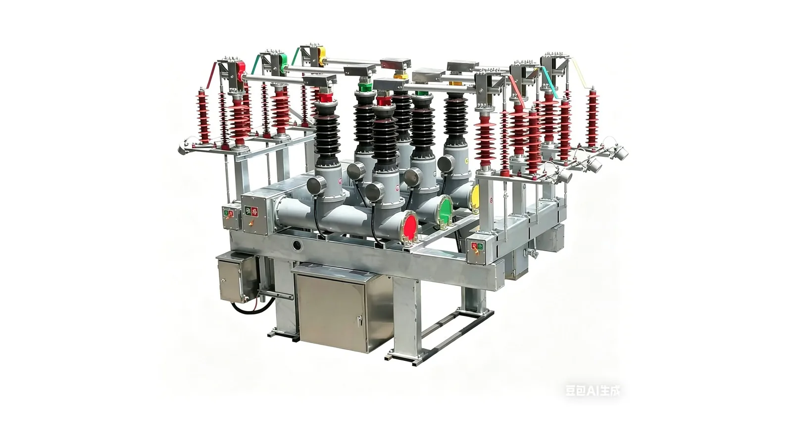
Combined breaker-disconnector path for 40.5 kV bay equipment where interruption and visible isolation are handled in one combined unit.
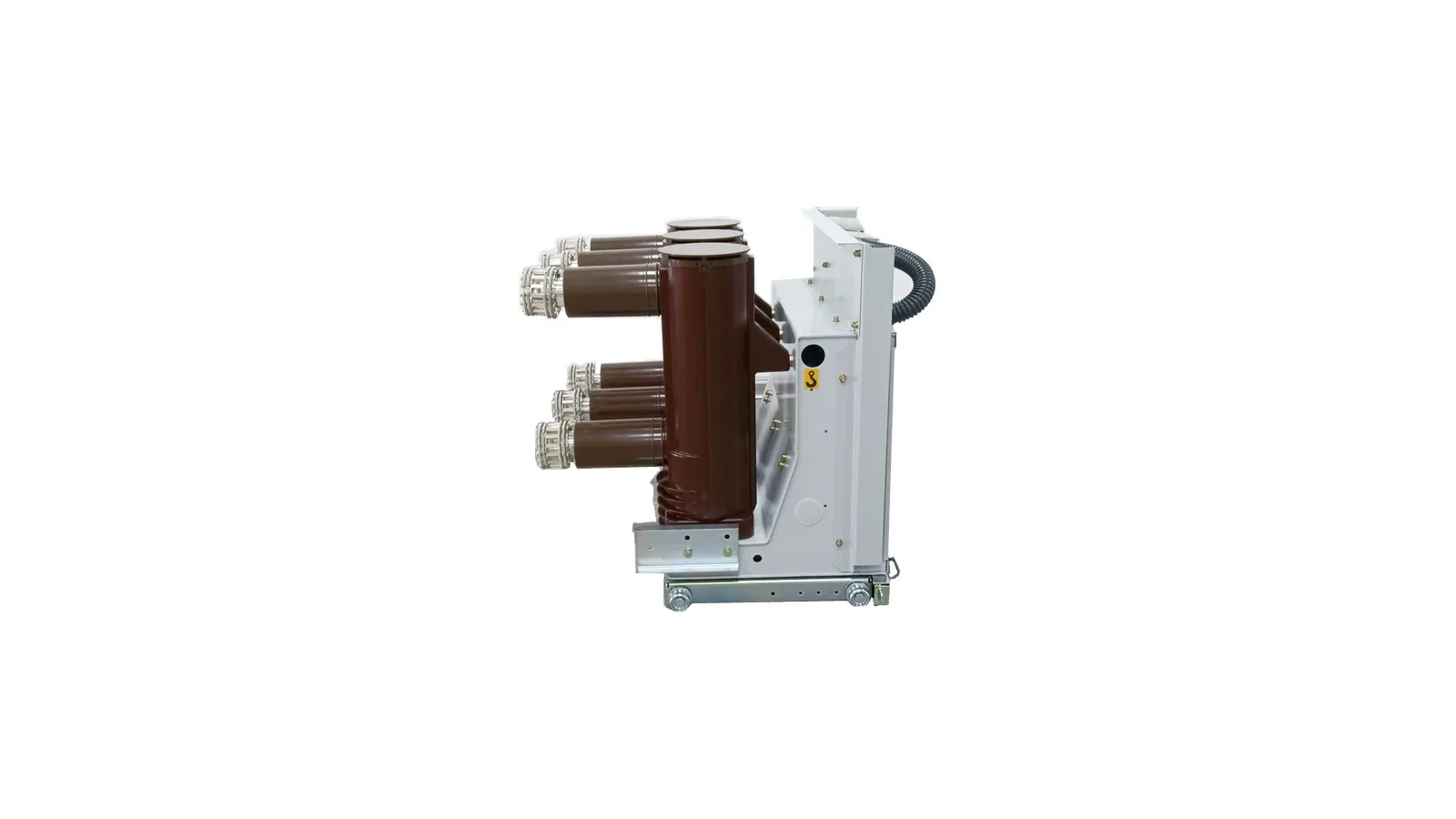
Indoor VCB family selector for VS1, VSG, ZN85B(VSG), VSM and ZN12 cabinet paths where voltage class and cabinet fit decide the route.

Side-mounted and panel-mounted VCB path where the available documents support product identity and cabinet fit but do not provide a clean drawing.
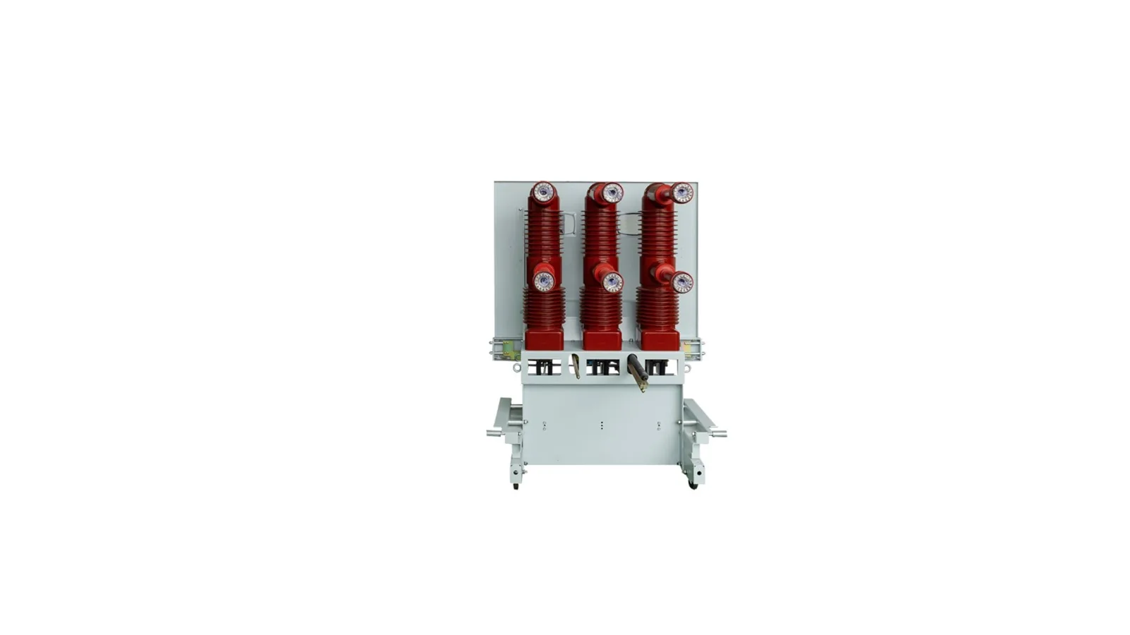
ZN85-40.5 indoor VCB path for KYN61-40.5 switchgear where draw-out layout, 40.5 kV insulation and 25 / 31.5 kA duty are selected together.
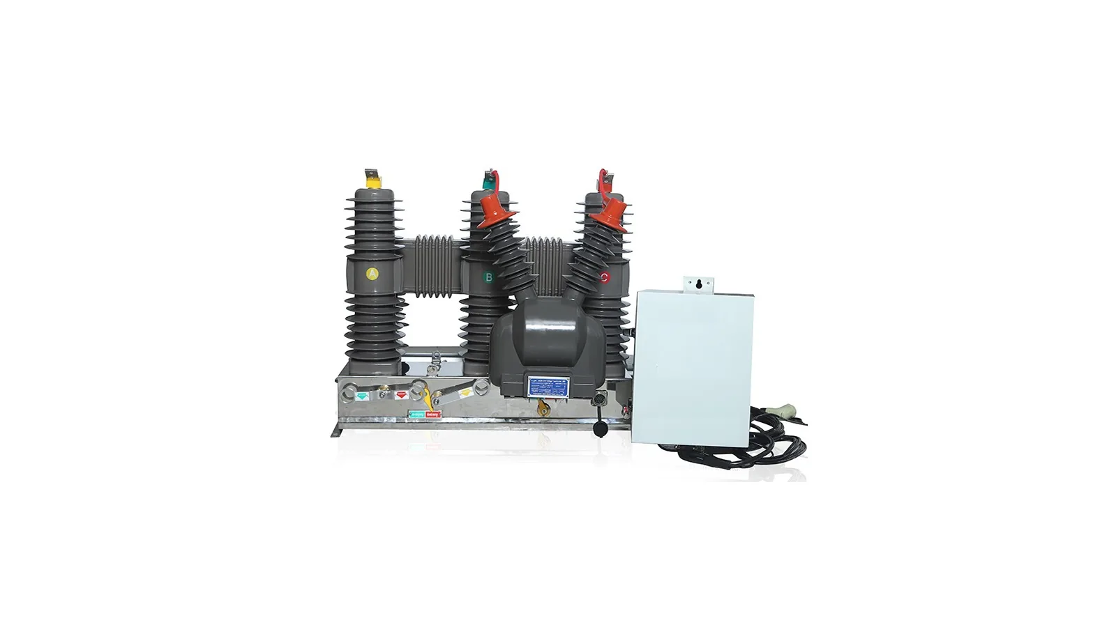
Outdoor pole-mounted VCB path for ZW20 and ZW32 feeder applications with manual, electric or remote-control operation.
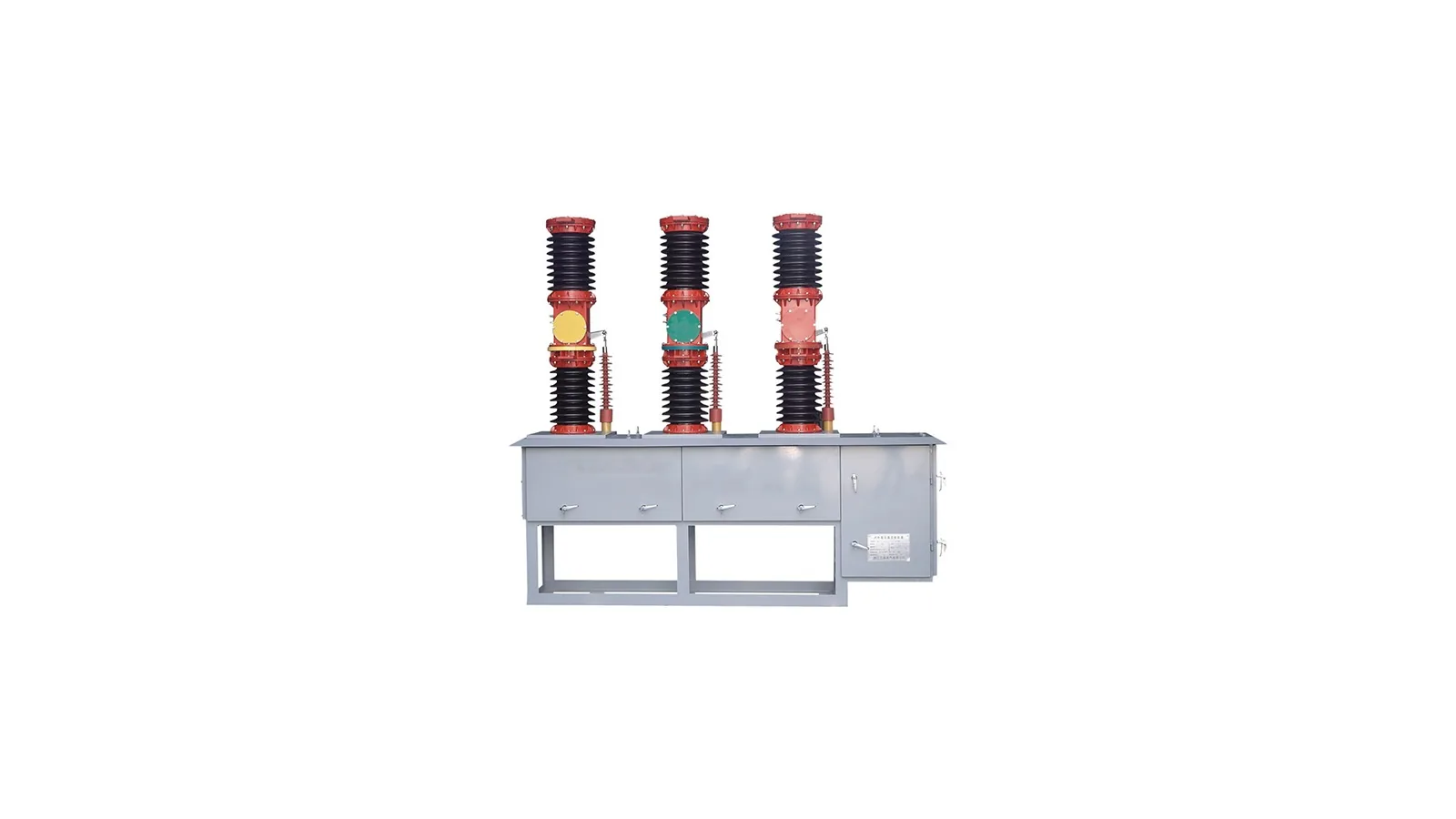
ZW7-40.5 station-type outdoor VCB path for foundation installation where pole material, CT arrangement and mechanism type define the package.
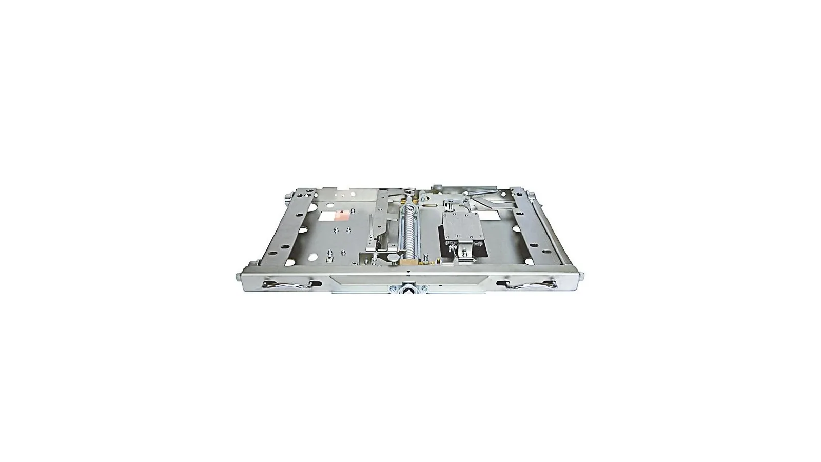
Accessory path for chassis trucks, contact arms, shutters, spouts, earthing parts and interlock items used with withdrawable vacuum circuit breakers.
Use this category when the project needs SF6, vacuum, combined bay, station or accessory paths for protection switching. Use load break switch or disconnect switch routes when the duty is switching load current or visible no-load isolation.
SF6, indoor VCB, pole VCB, station VCB and accessory rows stay separated by voltage class and installation package.
CB-01, CB-04, CB-06, CB-07, CB-08 and CB-09 include Drawing tabs for dimension checks.
Ratings come from product rating tables, technical PDFs or order-sheet confirmation.
Drawing tabs appear only where clean English drawings or clean cropped drawing views are available.
The application question comes first: HV substation bay, tank-type bay, combined bay, indoor switchgear, pole-mounted feeder, station foundation or accessory replacement.
Separate fault-current interruption from load switching and no-load visible isolation before choosing the breaker route.
Use SF6 rows when the bay requires gas-insulated interruption or a tank-type body.
Use VCB rows when the equipment is an indoor switchgear breaker, outdoor feeder breaker or station foundation breaker.
Use accessory rows only for compatibility, interlock and replacement part review.
This matrix is intentionally thin. It tells the engineer which product family to compare, then the product detail keeps the rating boundary for that route.
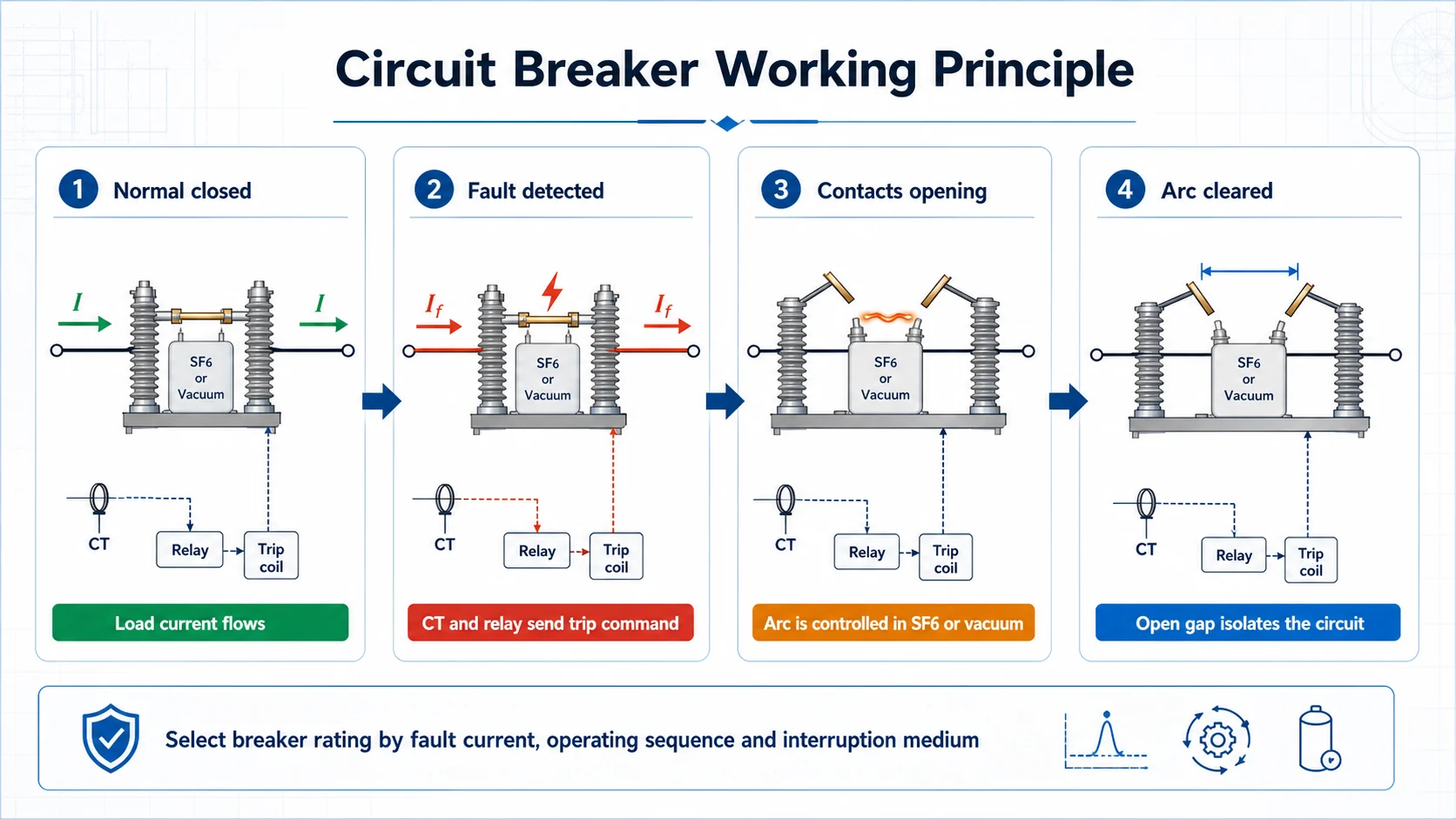
Use this sequence to separate breaker duty from load switching and no-load isolation: protection detects the fault, the trip mechanism opens the contacts, the arc is extinguished in SF6 or vacuum, and the open gap isolates the circuit.
Confirm the sequence against the selected product path before quotation.
The category does not reuse one breaker table across all routes. Each product detail states the supported rating range and what must be confirmed from the order sheet.
Voltage class, tank structure, SF6 pressure and combined-unit duty decide which model row applies.
Cabinet width, pole mounting, foundation layout and voltage class decide the quotation package.
White-background product views are used for route recognition. Scanned pages, Chinese-only pages and third-party references remain internal unless they can be processed into usable English or clean drawing views; teams can also download circuit breaker catalog PDFs before final model review.
Product cards avoid scan pages, scanned document screenshots and third-party reference visuals.
Photo-only or unclear routes do not receive invented voltage, current or breaking rows.
CB-01, CB-04, CB-06, CB-07, CB-08 and CB-09 include Drawing tabs. CB-02, CB-03 and CB-05 stay SPEC-only.
The third-party reference under CB-07 is kept internal and does not define the public spec table.
Send the product route and fault-interruption duty first, then match the medium, rating row, mechanism and mounting interface, or check certificates, test reports and RFQ forms when project files need review.
Outdoor SF6, dead tank, combined unit, indoor VCB, pole VCB, station VCB or accessory route.
Short-circuit breaking current, making current, short-time withstand and operating sequence.
Do not copy values across unrelated voltage classes or breaker structures.
Cabinet, pole, foundation, truck code, CT/PT, mechanism voltage and site data decide the package.
A circuit breaker is selected for fault-current interruption and protection switching. This page separates SF6, vacuum, combined bay, station and accessory paths before any model is released.
Select the route first when the project still needs to compare SF6 substation, dead tank, combined bay, indoor VCB, pole-mounted VCB, station VCB or accessory paths. The exact model row should follow the interruption duty, voltage class and mounting interface.
Drawing tabs are shown only where a clean English drawing or a cleanly processed drawing view is available. Mixed Chinese scan pages and unclear third-party material stay internal.
No. The accessory path supports cabinet and interlock compatibility. Breaker voltage, current and breaking duty must come from the matching breaker family or project order sheet.
Start from the installation point and interruption role. HV substation and tank routes use SF6 rows, while indoor cabinet, pole-mounted feeder and station routes use VCB rows.
Send product route, system voltage, rated current, short-circuit breaking current, operating sequence, mechanism voltage, CT or controller scope, mounting drawing, cabinet or foundation interface and destination standard.
Send the route, system voltage, rated current, breaking current, operating sequence, mechanism voltage, CT or controller scope, mounting interface, drawing status and destination standard. XIYA will return the suitable circuit breaker path, drawing check and required document list.