Load break switch product category

Load Break Switches for Feeder Switching and Ring Network Isolation

Use this selector to separate indoor AIS, SF6, puffer, outdoor air, fuse-combination, manual IACM, horn-gap, accessory, PGS, indoor vacuum and outdoor vacuum load break switch options before confirming ratings and drawings.

Product types

Load Break Switch Types

Choose by installation point, interruption medium, fuse or controller requirement, mounting interface and available rating data.

LBS 01Indoor AIS

Indoor High Voltage Load Break Switch

Indoor high-voltage load switch path for cabinet switching, line protection and fuse-combination review where the FN7-12 indoor LBS series is identified.

Send details
LBS 02SF6 insulated

SF6 Gas Insulated Load Break Switch

Gas-insulated load break switch path for compact distribution equipment, with 12 / 24 / 36 kV voltage classes confirmed before quotation.

Send details
LBS 03Puffer indoor

Three Pole Puffer Type Indoor Load Isolator

Indoor three-pole puffer load isolator path where the puffer mechanism and indoor cabinet fit are the first selection questions.

Send details
LBS 04Arc chute

Outdoor Air Load Break Switch with Arc Chute

Outdoor air load break switch option for 12 / 24 / 36 kV line switching where visible arc-chute hardware, pole mounting and operating linkage drive the choice.

Send details
LBS 05Fuse option

Medium Voltage Air Load Break Switch with Fuse

Medium-voltage air load break switch with fuse path for 12 / 24 / 36 kV projects where switching duty and fuse protection are selected together.

Send details
LBS 06Outdoor air

Three Pole Outdoor Air Break Load Isolator

Three-pole outdoor air-break load isolator path for 12 / 24 / 36 kV projects where product identity is clear and current or withstand duty still needs confirmation.

Send details
LBS 07Manual outdoor

IACM Manual Outdoor Load Break Switch

Manual outdoor IACM load break switch path with arcing-horn structure, polymer insulation and rod operation for overhead-line switching.

Send details
LBS 08Horn gap

Horn Gap Fuse Switch

Horn-gap fuse switch option for adjacent fuse switching material where the visual selection option is useful but full rating rows are not present.

Send details
LBS 09Accessories

Load Break Switch Accessories and Parts

Accessory and replacement-parts option for load break switch mechanisms, contacts, linkage parts and support hardware.

Send details
LBS 10Pole SF6

Pole Mounted SF6 Load Break Switch PGS

Pole-mounted SF6 PGS path for smart-grid or feeder automation projects where LBS duty crosses into distribution automation scope.

Send details
LBS 11Vacuum indoor

Indoor Vacuum Load Break Switch

Indoor vacuum load break switch path for FZN/FZRN style switchgear applications where vacuum interruption and cabinet fit need to be checked together.

Send details
LBS 12Vacuum outdoor

Outdoor Vacuum Load Break Switch

Outdoor vacuum load break switch path for FZW32 12 kV and 40.5 kV feeder switching with visible disconnecting fracture and pole mounting.

Send details
Technical parameters

Indoor High Voltage Load Break Switch selection boundary

Indoor high-voltage load switch path for cabinet switching, line protection and fuse-combination review where the FN7-12 indoor LBS series is identified.

Reference basisIndoor High-Voltage Load Break Switch reference set with product images and rating documents
Indoor high voltage load break switch product on clean white background
Indoor High Voltage Load Break Switch product view
Product type
FN7-12 Series Indoor H.V. Load Switch – Fuse Combination
Selection option
Core indoor load break switch option
Application point
Indoor switchgear, feeder switching and fuse-combination selection
Reference basis
Product images and rating documents
Drawing availability
Cleaned installation diagram is available in the modal Drawing tab
RFQ checks
Confirm cabinet layout, fuse option, earthing option, tripper and interlock logic from the order sheet

Indoor High Voltage Load Break Switch selection rows

Technical rowFN7-12 rating valueSelection note
Product variantsFN7-12, FN7-12DSL, FN7-12DXL, FN7-12R, FN7-12DSLR, FN7-12DXLR, FN7-12RAF, FN7-12DSLRAF, FN7-12DXLRAFUse the exact earth-switch, interlock, fuse, striker and trip-coil code from the order sheet
Rated voltage / maximum voltage12 kV / 12 kVFN7-12 rating row
Rated current400 / 630 ALoad switch and fuse-combination option
1 min power frequency withstand42 / 48 kVInsulation rating row
4 s short-time withstand12.5 / 20 kACurrent path selection must match the order row
Peak withstand and short-circuit controlling current31.5 / 50 kADo not mix with outdoor FKW or FZW rows
Breaking capacity400 / 630 ALoad current breaking row
Rated transfer current1000 AFuse-combination boundary
Fuse rated parametersSDLA*J 40 A uses 6.3 to 40 A fuse current; SFLA*J 100 A uses 50 to 100 A; SKLA*J 125 A uses 125 AFuse carrier must be confirmed before final selection
Service conditionsAltitude <=1000 m; ambient -25 to +40 deg C; RH daily 95% and monthly 90%Service-condition row
Selection note

Use this product type for initial selection. If a value is not listed for this option, confirm it from the project sheet before quotation.

FN7-12 installation diagram cropped to the clean dimension drawing area
Technical parameters

SF6 Gas Insulated Load Break Switch selection boundary

Gas-insulated load break switch path for compact distribution equipment, with 12 / 24 / 36 kV voltage classes confirmed before quotation.

Reference basisSF6 Gas Insulated Load Break Switch reference set with product image and rating documents
SF6 gas insulated load break switch product with sealed switching tank and terminals
SF6 Gas Insulated Load Break Switch product view
Product type
SF6 Gas Insulated Load Break Switch
Selection option
Distribution equipment LBS path
Voltage classes
12 / 24 / 36 kV
Interruption and insulation option
Gas-insulated switching chamber
Reference basis
Product image and rating documents
Drawing availability
SPEC-only. Request dimensions with the RFQ when cabinet mounting details matter
RFQ checks
Confirm voltage class, rated current, operation type, tank interface and controller requirement

SF6 Gas Insulated Load Break Switch selection rows

Technical rowLoad break switchFuse-switch combination
Model seriesFLRN36 gas-insulated LBS seriesFLRN36 fuse-switch combination series
Standards listedIEC 420, IEC 62271-105, GB 16926, GB/T 11022Same technical page
Rated voltage / frequency12 / 24 / 36 kV; 50 Hz12 / 24 / 36 kV; 50 Hz
Rated current630 A125 A
Short-circuit making / short-time / peak withstand50 kA peak / 20 kA / 50 kAShort-circuit breaking 50 kA
Active load / closed-loop / cable charging breaking630 A / 630 A / 10 AConfirm fuse package before quoting
5% active load / transfer current31.5 A1550 A transfer current
Insulation levelPF 42 / 49 kV; impulse 75 / 85 kVSame insulation row
Circuit resistance / mechanical life<=70 micro-ohm excluding fuse resistance; 2000 operationsUse as rating boundary only
Earthing-switch rows20 kA short-time, 50 kA peak and making, 4 s, 2000 operationsApplies when D earthing switch is selected
Working environmentAltitude <=1000 m; -25 to +40 deg C; RH daily <=95%, monthly <=90%; seismic <=8 degreeWorking-condition row
Selection note

Use this product type for initial selection. If a value is not listed for this option, confirm it from the project sheet before quotation.

Technical parameters

Three Pole Puffer Type Indoor Load Isolator selection boundary

Indoor three-pole puffer load isolator path where the puffer mechanism and indoor cabinet fit are the first selection questions.

Reference basisThree-pole Puffer-type Indoor Load Isolator reference set with product image and rating documents
Three pole puffer type indoor load isolator product on white background
Three Pole Puffer Type Indoor Load Isolator product view
Product type
Three-pole Puffer-type Indoor Load Isolator
Identified series
FN18 indoor puffer load switch technical table
Selection option
Indoor puffer-type load isolator path
Reference basis
Product image and rating documents
Drawing availability
Cleaned mechanism size detail is available in the modal Drawing tab
RFQ checks
Confirm puffer mechanism package, operating drive, cabinet mounting and interlock requirement

Three Pole Puffer Type Indoor Load Isolator selection rows

Technical rowRating valueSelection note
Voltage classes12 / 17.5 / 24 / 36 / 40.5 kVFN18 / FN18-DR rating table
Rated current400 / 630 / 1250 A at 12 to 24 kV; 630 / 800 / 1000 A at 36 to 40.5 kVPick by voltage class and cabinet option
Short-circuit making capacity67 kA peak at 12 kV; 50 kA peak at 17.5 to 40.5 kVTechnical table
Mainly active load breaking capacity400 / 630 / 1250 A at 12 to 24 kV; 630 / 800 A rows for higher voltage classesDo not reuse for SF6 or vacuum options
Capacitive / inductive breaking capacityCapacitive 150 A at 12 kV, 45 A at 17.5 kV, 80 A at 24 kV, 50 A at 36 to 40.5 kV; inductive 16 APuffer option boundary
Fuse co-operation max breaking1600 A at 12 / 17.5 kV; 900 A at 24 kV; 300 A at 36 / 40.5 kVListed against IEC 62271-104 / IEC 420
1 min PF withstand42/45, 45/60, 55/70, 80/88, 95/120 kV by voltage classEarth-to-pole / isolating-distance pairs
Lightning impulse withstand75/85, 95/110, 125/145, 170/195, 190/220 kV by voltage classEarth-to-pole / isolating-distance pairs
Pole distance and operationPole distance P 150 to 360 mm by class; shaft angle 130 deg for lower classes and 120 deg for 36 to 40.5 kVConfirm exact mechanism side from drawing
Selection note

Use this product type for initial selection. If a value is not listed for this option, confirm it from the project sheet before quotation.

Indoor puffer operating mechanism size detail processed from the English dimension drawing
Technical parameters

Outdoor Air Load Break Switch with Arc Chute selection boundary

Outdoor air load break switch option for 12 / 24 / 36 kV line switching where visible arc-chute hardware, pole mounting and operating linkage drive the choice.

Reference basisOutdoor air load break switch with arc chute reference set with product images and rating documents
Outdoor air load break switch with arc chute and porcelain insulators
Outdoor Air Load Break Switch with Arc Chute product view
Product type
FKW18-12/24/36 Series Outdoor HV Load Break Switch
Selection option
Outdoor arc-chamber and load-disconnector path
Voltage classes
12 / 24 / 36 kV
Application point
Pole-mounted outdoor feeder switching option
Reference basis
Product images and rating documents
Drawing availability
Cleaned FKW18 structure drawing is available in the modal Drawing tab
RFQ checks
Confirm voltage class, pole spacing, arc chute package, operation side and mounting pole data

Outdoor Air Load Break Switch with Arc Chute selection rows

Technical rowFKW18 rating valueSelection note
Rated voltage / frequency12 / 24 / 36 kV; 50 / 60 HzFKW18-12/24/36 rating table
Rated current630 ASame table for all listed voltage columns
Rated peak / short-time withstand / duration50 kA / 20 kA / 4 sOutdoor arc-chute option
Rated active load / loop / cable-charging breaking630 A / 630 A / 10 AUse for FKW18 series only
5% active load and transformer breaking31.5 A and 1250 ARated-data rows 10 and 11
Rated short-circuit making current50 kADo not copy to photo-only outdoor option
Main loop resistance<=90 micro-ohm at 12 kV; <=95 micro-ohm at 24 / 36 kVRated-data table
1 min PF withstandDry phase-to-phase/to-earth 42 / 65 / 95 kV; dry across open contacts 49 / 79 / 115 kV; wet phase-to-earth 30 / 63 / 85 kVColumns follow 12 / 24 / 36 kV
Lightning impulse withstand75/85, 125/145, 185/215 kVPhase-to-phase or to-earth / across open contacts
Mechanical life2000 operationsRated-data row
Operation rowsThree-phase open/close asynchronous <=5 ms; motor <=220 V and <=200 W; blade deflection <=2 mm; main blade pressure 420 +/-42 N; operating moment <=300 NmConfirm control voltage in RFQ
Ambient conditionsAltitude <=3000 m; -25 to +40 deg C; wind speed <=35 m/s; pollution degree <=IV; earthquake <=8 degree; ice thickness <=10 mmAmbient-condition block
Selection note

Use this product type for initial selection. If a value is not listed for this option, confirm it from the project sheet before quotation.

FKW18 outdoor load break switch structure drawing cropped to the dimension view
Technical parameters

Medium Voltage Air Load Break Switch with Fuse selection boundary

Medium-voltage air load break switch with fuse path for 12 / 24 / 36 kV projects where switching duty and fuse protection are selected together.

Reference basisMedium Voltage Air Load Break Switch with fuse reference set with product image and technical reference
Medium voltage air load break switch with fuse assembly on white background
Medium Voltage Air Load Break Switch with Fuse product view
Product type
Medium Voltage Air Load Break Switch with Fuse
Voltage classes
12 / 24 / 36 kV
Selection option
Fuse-combination LBS selection option
Reference basis
Clean product image and technical reference
Drawing availability
SPEC-only. Request dimensions with the RFQ when mounting details matter
RFQ checks
Confirm fuse package, rated current, protection duty, pole mounting and operation side

Medium Voltage Air Load Break Switch with Fuse selection rows

Selection fieldWhat is supported
Voltage classes12 / 24 / 36 kV
Rated current hint630 A
Protection interfaceLoad break switch plus fuse package
Do not mix withDo not mix this path with pure disconnect-switch pages
What to confirmFuse carrier, fuse link, load-breaking current and installation drawing
Selection note

Use this product type for initial selection. If a value is not listed for this option, confirm it from the project sheet before quotation.

Technical parameters

Three Pole Outdoor Air Break Load Isolator selection boundary

Three-pole outdoor air-break load isolator path for 12 / 24 / 36 kV projects where product identity is clear and current or withstand duty still needs confirmation.

Reference basisThree-pole Outdoor Air-Break Load Isolator reference set with product images and no complete public rating table
Three pole outdoor air break load isolator with support frame and operating linkage
Three Pole Outdoor Air Break Load Isolator product view
Product type
Three-pole Outdoor Air-Break Load Isolator
Selection option
Outdoor three-pole air-break load isolator path
Application point
Outdoor line isolation with load-switching context
Voltage classes
12 / 24 / 36 kV
Reference basis
Product images are available; no complete public rating table is available
Drawing availability
SPEC-only. No clean English drawing was found in this folder
RFQ checks
Confirm ratings from the order sheet before quoting voltage, current or withstand values

Three Pole Outdoor Air Break Load Isolator selection rows

Selection fieldWhat is supported
Product identityThree-pole outdoor air-break load isolator
Voltage classes12 / 24 / 36 kV
Visible product evidenceFrame, insulators and operating linkage visible in photos
Data limitPhoto-only option for structure and appearance
What to confirmVoltage, current, short-time duty, pole spacing and handle option
Selection note

Use this product type for initial selection. If a value is not listed for this option, confirm it from the project sheet before quotation.

Technical parameters

IACM Manual Outdoor Load Break Switch selection boundary

Manual outdoor IACM load break switch path with arcing-horn structure, polymer insulation and rod operation for overhead-line switching.

Reference basisIACM manual outdoor load break switch reference set with French technical sheets, quotations and product images
IACM manual outdoor load break switch with arcing horn and polymer insulators
IACM Manual Outdoor Load Break Switch product view
Product type
IACM manual outdoor load break switch
Reference type
French consultation and technical data sheets, translated working files and product images
Visible type rows
HFKW-24KV / 200A and HFKW-36KV / 200A in the technical table
Standards listed
CEI 62271-1, 102, 103, 200, CEI 60529, CEI 62262
Drawing availability
SPEC-only. Request dimensions with the RFQ because the available drawing-like pages are not ready for publication
RFQ checks
Confirm final network voltage, manual rod set, support height, creepage and accessories

IACM Manual Outdoor Load Break Switch selection rows

Technical row24 kV network path36 kV network path
Rated voltage24 kV36 kV
Rated frequency50 Hz50 Hz
Interrupting mediumAirAir
Class and mechanical enduranceE3 / M1E3 / M1
Lightning impulse withstand125 kV to earth / 145 kV isolating distance170 kV to earth / 195 kV isolating distance
Power frequency withstand50 kV to earth / 60 kV isolating distance70 kV to earth / 80 kV isolating distance
Rated short-time withstand12.5 kA10 kA
Rated peak withstand31.5 kA25 kA
Continuous current200 A200 A
Closed-loop breaking200 A200 A
Short-circuit making31.5 kA25 kA
Active load breaking row50 / 100 A50 / 100 A
No-load transformer breaking2.5 ATo be specified in the 36 kV table
No-load line breaking10 ATo be specified in the 36 kV table
Minimum creepage and bushing material900 mm; synthetic MV bushings>=900 mm; synthetic MV bushings
Manual drive and pole countRod operation; 3 poles; IP00Rod operation; 3 poles; IP00
Selection note

Use this product type for initial selection. If a value is not listed for this option, confirm it from the project sheet before quotation.

Technical parameters

Horn Gap Fuse Switch selection boundary

Horn-gap fuse switch option for adjacent fuse switching material where the visual selection option is useful but full rating rows are not present.

Reference basisHorn Gap Fuses Switch, 7 product photos and 1 operation manual
Horn gap fuse switch product assembly on clean white background
Horn Gap Fuse Switch product view
Product type
Horn Gap Fuse Switch
Selection option
Horn-gap fuse switching accessory option
Application point
Fuse switching option with horn-gap arc path
Reference basis
Product images and operation manual
Drawing availability
SPEC-only. Request dimensions with the RFQ when mounting details matter
RFQ checks
Confirm fuse link, cutout fit, voltage class and operation sequence before quotation

Horn Gap Fuse Switch selection rows

Selection fieldWhat is supported
Product identityHorn-gap fuse switch
Visible product evidenceHorn gap, fuse carrier and outdoor hardware visible in product images
Do not mix withDo not merge with fuse-disconnect switch data without a matching rating row
What to confirmVoltage, fuse rating, breaking duty and mounting interface
Selection note

Use this product type for initial selection. If a value is not listed for this option, confirm it from the project sheet before quotation.

Technical parameters

Load Break Switch Accessories and Parts selection boundary

Accessory and replacement-parts option for load break switch mechanisms, contacts, linkage parts and support hardware.

Reference basisAccessories and Parts reference set with product images and service media
Load break switch accessories and replacement parts on white background
Load Break Switch Accessories and Parts product view
Product type
Load Break Switch Accessories and Parts
Selection option
Accessory group, not a standalone rated switch path
Application point
Replacement parts, support hardware, operating parts and service items
Reference basis
Accessory images and service media for compatibility review
Drawing availability
SPEC-only. Request part dimensions with the RFQ when fit must be checked
RFQ checks
Match part type, switch model, material, dimensions and quantity to the original equipment

Load Break Switch Accessories and Parts selection rows

Selection fieldWhat to check
Part roleContact, linkage, arc part, bracket or service accessory
CompatibilityMatch to the switch model and mechanism side
Data limitAccessory photos do not define complete switch ratings
What to confirmModel, material, dimension, hole pattern and quantity
Selection note

Use this product type for initial selection. If a value is not listed for this option, confirm it from the project sheet before quotation.

Technical parameters

Pole Mounted SF6 Load Break Switch PGS selection boundary

Pole-mounted SF6 PGS path for smart-grid or feeder automation projects where LBS duty crosses into distribution automation scope.

Reference basisSF6 Pole-mounted Load Break Switch PGS reference set with technical image
Pole mounted SF6 load break switch PGS product with control enclosure
Pole Mounted SF6 Load Break Switch PGS product view
Product type
Pole Mounted SF6 Load Break Switch PGS
Selection option
Cross-use LBS and smart-grid product category
Visible model row
12/24/36 kV and 20 kA appear in the reference image label
Reference basis
Technical image from the SF6 pole-mounted load break switch reference set
Drawing availability
SPEC-only. Request dimensions with the RFQ when mounting details matter
RFQ checks
Confirm controller scope, voltage class, short-circuit duty, communication and pole mounting

Pole Mounted SF6 Load Break Switch PGS selection rows

Selection fieldWhat is supported
Voltage series note12 / 24 / 36 kV in the reference label
Short-circuit duty note20 kA in the reference label
Automation boundaryConfirm whether the RFQ includes switch body only or controller package
What to confirmRated current, controller, CT/PT, battery, communication and mounting bracket
Selection note

Use this product type for initial selection. If a value is not listed for this option, confirm it from the project sheet before quotation.

Technical parameters

Indoor Vacuum Load Break Switch selection boundary

Indoor vacuum load break switch path for FZN/FZRN style switchgear applications where vacuum interruption and cabinet fit need to be checked together.

Reference basisIndoor Type Vacuum Load Break Switch reference set with product images, FZN21-40.5 technical PDF and one DWG drawing candidate
Indoor vacuum load break switch mechanism and interrupter assembly
Indoor Vacuum Load Break Switch product view
Product type
Indoor Vacuum Load Break Switch
Identified model
FZN21-40.5 technical document and FZRN21-40.5 drawing
Selection option
Indoor vacuum load break switch option
Reference basis
Product images, technical PDF and DWG drawing candidate
Drawing availability
Cleaned outline drawing is available in the modal Drawing tab
RFQ checks
Confirm indoor cabinet width, fuse-combination option, earthing option and operation mechanism

Indoor Vacuum Load Break Switch selection rows

Technical rowFZN21-40.5 load switchFZRN21-40.5D fuse combination
Rated voltage / frequency40.5 kV / 50 Hz40.5 kV / 50 Hz
Rated current1250 / 630 AFuse rated current 63 A
Rated short-circuit breakingNot listed for pure load switch25 / 31.5 kA
Rated active load / closed-loop breaking1250 / 630 A; 1250 / 630 AFuse-combination row to confirm by order
Cable charging / line charging / earth-fault breaking21 A / 2.1 A / 63 AUse rating table boundary
Rated short-circuit making / peak withstand50 kA / 50 kAFuse-combination making row is separate
Rated short-time withstand20 kA / 4 s for load switch; 20 kA / 2 s for earthing switchConfirm cabinet earthing option
Rated transfer currentNot applicable1700 A
1 min PF withstand95 / 115 kVPhase-to-earth or phase-to-phase / vacuum or isolating gap
Lightning impulse withstand185 / 215 kVPhase-to-earth or phase-to-phase / vacuum or isolating gap
Main circuit resistance / mechanical life<=120 micro-ohm excluding fuse; 10000 operations<=120 micro-ohm excluding fuse; 10000 operations
Vacuum interrupter operation rowsContact opening 19 +/-1 mm; contact wear allowance 3 mm; average opening speed 1.6 +/-0.2 m/s; average closing speed 0.8 +/-0.2 m/sSame mechanism series unless order states otherwise
Mechanism powerAC/DC 220 V or 110 V; output <=70 W; working voltage 85% to 110% rated voltagePermanent-magnet bistable DC motor row
Service conditionsAltitude <=2500 m; -40 to +50 deg C; RH daily <=95% and monthly <=90%; seismic <=7 degree; inclination <=5 degreeTranslated from the technical document
Selection note

Use this product type for initial selection. If a value is not listed for this option, confirm it from the project sheet before quotation.

FZN21 indoor vacuum load break switch outline drawing cleaned from the drawing document
Technical parameters

Outdoor Vacuum Load Break Switch selection boundary

Outdoor vacuum load break switch path for FZW32 12 kV and 40.5 kV feeder switching with visible disconnecting fracture and pole mounting.

Reference basisOutdoor Type Vacuum Load Break Switch reference set with product images, technical documents and installation-size drawing PDF
Outdoor vacuum load break switch with three pole frame and insulators
Outdoor Vacuum Load Break Switch product view
Product type
Outdoor Vacuum Load Break Switch
Identified models
FZW32-12 and FZW32-40.5 technical PDFs
Selection option
Outdoor vacuum load break switch option
Reference basis
Product images, technical documents and drawing PDF
Drawing availability
Cleaned installation diagram is available in the modal Drawing tab
RFQ checks
Confirm voltage class, rated current, pole spacing, manual or motor operation and controller scope

Outdoor Vacuum Load Break Switch selection rows

Technical rowFZW32-12 technical PDFFZW32-40.5 technical PDF
Rated voltage12 kV40.5 kV
Rated current630 A630 A
Rated active load breaking current630 A630 A
Rated closed-loop breaking current630 A630 A
5% rated active load breaking current31.5 A31.5 A
Cable charging breaking current10 A10 A
No-load transformer breaking capacity1600 kVA1250 kVA
Capacitor bank breaking / short-circuit closing100 A / 50 kAShort-circuit closing 50 kA
Rated short-time withstand current20 kA / 4 s20 kA / 4 s
Rated peak withstand current50 kA50 kA
1 min PF withstand42 / 48 kVDry 95 / 115 kV; wet 85 kV phase-to-earth
Lightning impulse withstand75 / 85 kV185 / 215 kV
Loop resistanceAuxiliary circuit <=300 micro-ohmMajor loop <=95 micro-ohm
Mechanical life10000 times10000 times
Vacuum interrupter and motionContact erosion limit 0.5 mm; open-contact clearance 5 +/-1 mm; average opening speed 1.1 +/-0.2 m/sContact-knife deviation <=5 mm; clearance between contact knives >=360 mm
Three-phase asynchronismOpening <5 ms; closing <2 msOpening/closing <=15 ms
Installation width and phase distanceSingle pole horizontal 1300 mm width, AB 750 mm, BC 320 mm; vertical 1230/1050 mm width with 500/400 mm spacing rows40.5 kV installation sizes are in the Drawing tab
Selection note

Use this product type for initial selection. If a value is not listed for this option, confirm it from the project sheet before quotation.

FZW32 outdoor vacuum load switch installation diagram cropped from the installation-size PDF
Application fit

Load Break Switch Applications

The application question comes first: indoor cabinet, outdoor feeder, ring network, fuse protection, manual overhead operation, automation or accessory replacement.

Switching role

Load break duty is selected by where the circuit is opened under load.

Separate load switching from visible no-load isolation. If the equipment is only for isolation, compare disconnect switch pages instead.
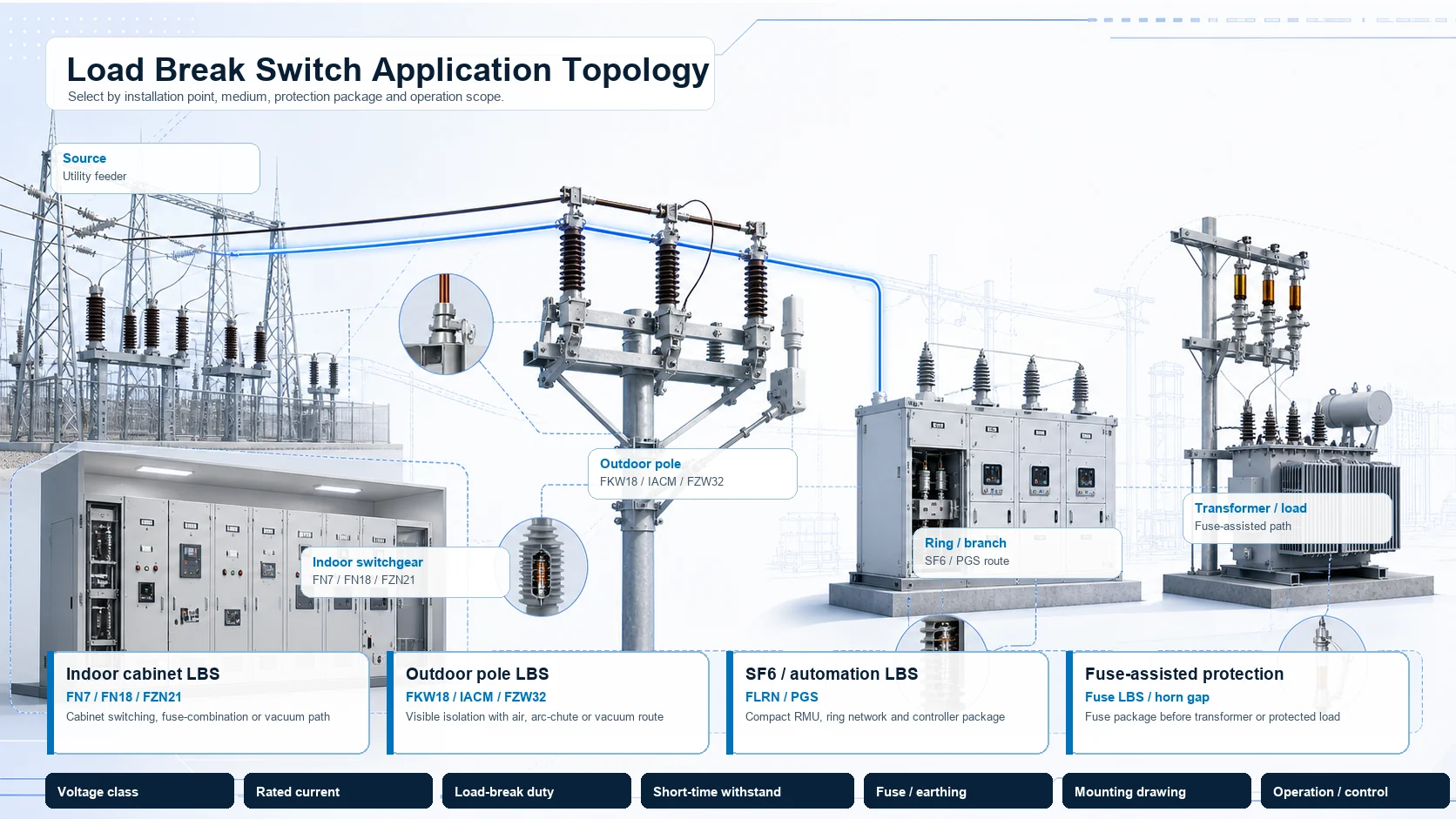
Engineering topology diagram showing load break switch positions in feeder ring and transformer protection options
Indoor option

Cabinet switching and vacuum interrupter options

Use FN7, FN18 or FZN21 when the switch sits inside a panel or switchgear cabinet.

Outdoor option

Pole-mounted air, IACM or vacuum options

Use FKW18, IACM, FZW32 or three-pole outdoor air options when the site is an overhead feeder.

Protection option

Fuse-combination and horn-gap options

Use fused or horn-gap options only when the project needs switching plus fuse protection review.

Selection matrix

Load Break Selection Matrix

Compare the product type, interruption medium and rating data before quotation.

Decision option
Interruption option
Rating data
Indoor cabinet optionFN7 / FN18 / FZN21
Indoor AIS or vacuum
Cabinet interface, mechanism side, fuse and interlock
Outdoor air optionFKW18 / three-pole outdoor / IACM
12 / 24 / 36 kV arc-chute, air-break or manual rod operation
Pole spacing, support height, handle operation and withstand duty
Fuse or horn-gap option12 / 24 / 36 kV fuse-combination / horn-gap fuse switch
Switching plus fuse protection
Fuse carrier, fuse link, protection duty and mounting fit
SF6 option12 / 24 / 36 kV SF6 gas-insulated / PGS pole-mounted SF6
Sealed gas chamber and optional controller
Short-circuit duty, controller scope and communications
Accessory optionAccessories and parts
Part replacement or service package
Switch model, part dimensions, material and quantity
Outdoor vacuum optionFZW32-12 / FZW32-40.5
Vacuum interrupter with disconnecting fracture
Pole mounting, manual or motor operation and installation drawing
Structure

Interruption Medium and Mounting

After the product type is selected, check the switching chamber, contact path, operating drive and mounting interface from the matching technical documents.
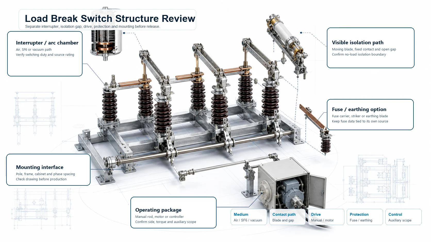
Structure schematic for load break switch interruption medium operating drive contact path and mounting interface

Structure inputs

Use these checks before the product type is selected.

Interruption mediumAir, puffer, SF6 or vacuum option must match the application point.
Contact pathArc chute, vacuum interrupter, horn gap, fuse carrier or disconnecting fracture.
Operating driveManual rod, hook operation, panel mechanism, motor drive or controller package.
Mounting fitCabinet, pole, cross-arm, support height, phase spacing and accessory interface.
Rating boundary

Load Break Switch Ratings

The category does not reuse one product table across all options. Each product detail states the supported rating range and what must be confirmed from the order sheet.

Indoor

FN7, FN18 and FZN21 stay in the cabinet option.

Do not mix puffer, fuse-combination and vacuum values unless the order sheet names the same model series.

Outdoor

FKW18, IACM, FZW32 and three-pole outdoor options require site mounting data.

Pole spacing, support height, operation side and drawing status decide the quotation package.

FKW1812 / 24 / 36 kV reference title for arc-chute and fused options

Keep arc-chute and fused rows separate.

IACM24 kV and 36 kV manual outdoor rows

Use the French technical sheet as SPEC evidence only.

PGS12 / 24 / 36 kV and 20 kA reference note

Confirm current and controller package before quotation.

FZW3212 kV and 40.5 kV outdoor vacuum rows

Use the modal table for verified values from the PDFs.

Document review

Drawings and Technical Documents

White-background product views are used for configuration recognition. Scanned pages, French sheets and Chinese drawings remain internal unless they can be processed into a usable English or clean drawing view; teams can also download load break switch catalog PDFs before final model review.
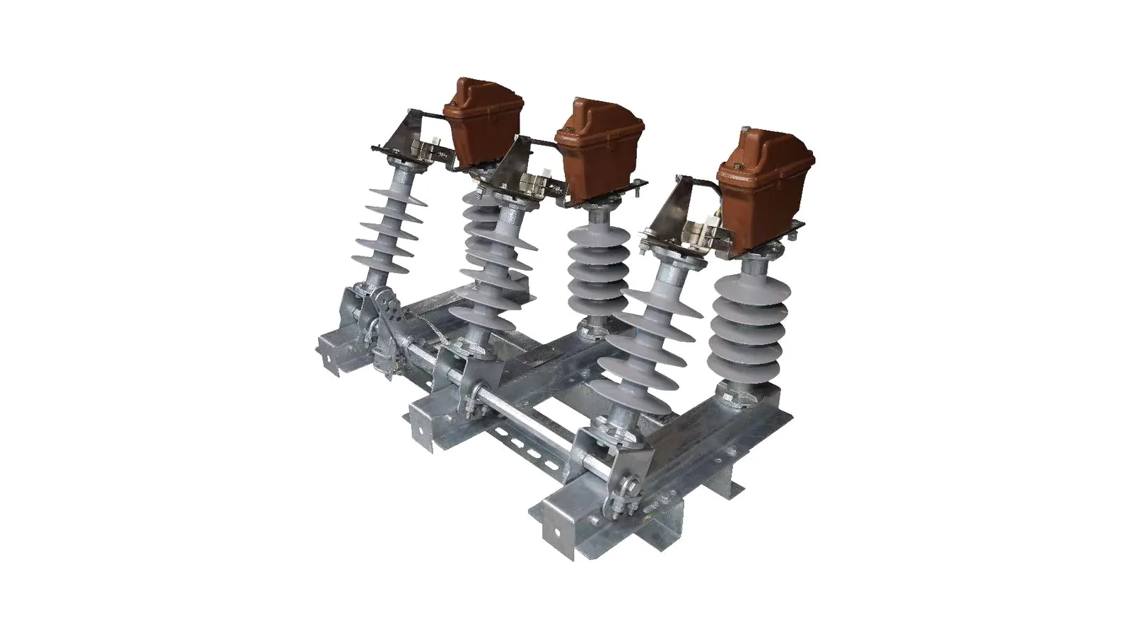
Outdoor air load break switch with arc chute and porcelain insulators
Clean outdoor air LBS product identity
Engineering topology diagram showing load break switch positions in feeder ring and transformer protection options
Feeder and ring network placement
Structure schematic for load break switch interruption medium operating drive contact path and mounting interface
Medium, drive and mounting checks
Product identity

Use white-background product images

Product cards avoid scan pages and scanned document screenshots.

SPEC boundary

State only what the available documents support

Image-supported options do not receive invented voltage or current rows.

Drawing boundary

Show Drawing only for processed usable views

FN7, FN18, FKW18, FZN21 and FZW32 include Drawing tabs. IACM stays SPEC-only because the available drawing-like documents are French.

Cross-category boundary

Keep this under Load Break Switches

These options are not moved under disconnect switches, even when a reference name includes isolator or disconnecting fracture.

Engineering selection

Load Break Switch RFQ Data

Send the product type and the switching duty first, then match the medium, rating row, operation method and mounting interface, or check certificates, test reports and RFQ forms when project files need review.

01 / TypeSelect the product type

Indoor, outdoor, SF6, vacuum, fused, horn-gap, accessory or PGS option.

02 / MediumMatch interruption medium

Air, puffer, SF6 or vacuum must match the feeder application.

03 / RatingUse the matching model row

Do not copy values across unrelated product types.

04 / MountingRelease from drawing or project sheet

Cabinet, pole, cross-arm, support height, operation side and controller scope decide the package.

Product typeOne of the 12 load break switch options.
System voltage12, 24, 36, 40.5 kV or project value.
Rated currentUse the rating table or project order sheet.
Switching dutyActive load, closed-loop, cable charging or transformer switching duty.
Interruption mediumAir, puffer, SF6 or vacuum.
Protection optionFuse carrier, horn gap, controller or accessory scope.
Mounting interfaceIndoor cabinet, pole, cross-arm, support or bracket.
Operation and siteManual, motorized, rod operation, controller and destination standard.
FAQ

Load Break Switch FAQ

What load break switch data is needed for RFQ?

Send the product type, system voltage, rated current, interruption medium, switching duty, fuse or controller requirement, mounting interface, operation side, drawing status, quantity and destination standard.

Where is a load break switch used?

Use a load break switch on indoor cabinets, ring networks, outdoor feeders, transformer branches or automation points where the circuit must open and close load current.

When should engineers choose the product type before the model?

Choose the product type first when the project still needs to compare indoor cabinet, outdoor feeder, SF6, vacuum, fused, horn-gap, accessory or PGS options. The exact model row should follow the installation point, interruption medium and mounting interface.

When are load break switch Drawing tabs available?

Drawing tabs are shown only where a clean drawing or a cleanly cropped English drawing view is available. French, Chinese, scanned or poster-style pages stay internal and the modal remains SPEC-only.

Can accessories define load break switch ratings?

No. Accessories and parts support compatibility review only. Voltage, current and withstand duty must come from the matching switch model or project order sheet.

How should engineers choose between air, SF6 and vacuum options?

Start from the installation point and interruption medium. Indoor cabinets use indoor AIS or vacuum options, outdoor pole feeders use air, IACM or vacuum options, and compact or automation projects may use SF6 or PGS options.

Request Load Break Switch Quote

Send the product type, system voltage, rated current, interruption medium, switching duty, fuse or controller requirement, mounting interface, operation side, available drawing and destination standard. XIYA will return the suitable load break switch option, drawing check and required document list.

Send Project Details
