Quotation form
Send an inquiry
Start with the basics. Our team can follow up for missing drawings, standards or packing details.
Submitted details are used only for quotation, technical review and project communication.
Compare composite crossarm, horizontal line, pin, post, suspension, transformer bushing, wall bushing, CT-integrated bushing, porcelain bushing, HTV silicone rubber compound and accessory interfaces by installation interface, rating boundary and dimension requirement.
Start with the installation interface, then compare the matching option by insulation duty, mechanical load, fitting interface and dimension requirement.
Composite crossarm insulator interface for insulated overhead crossarms where the square core, silicone housing, end fittings and interface load must be confirmed together.
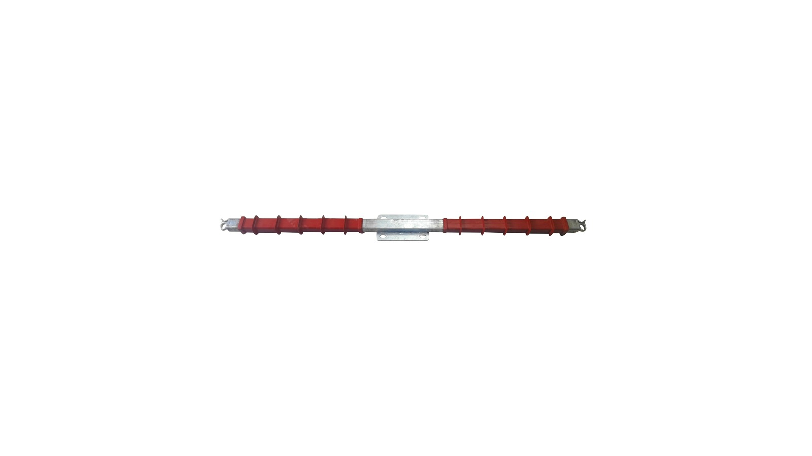
33 kV horizontal line composite insulator interface for line post or horizontal support duty on overhead feeder structures.
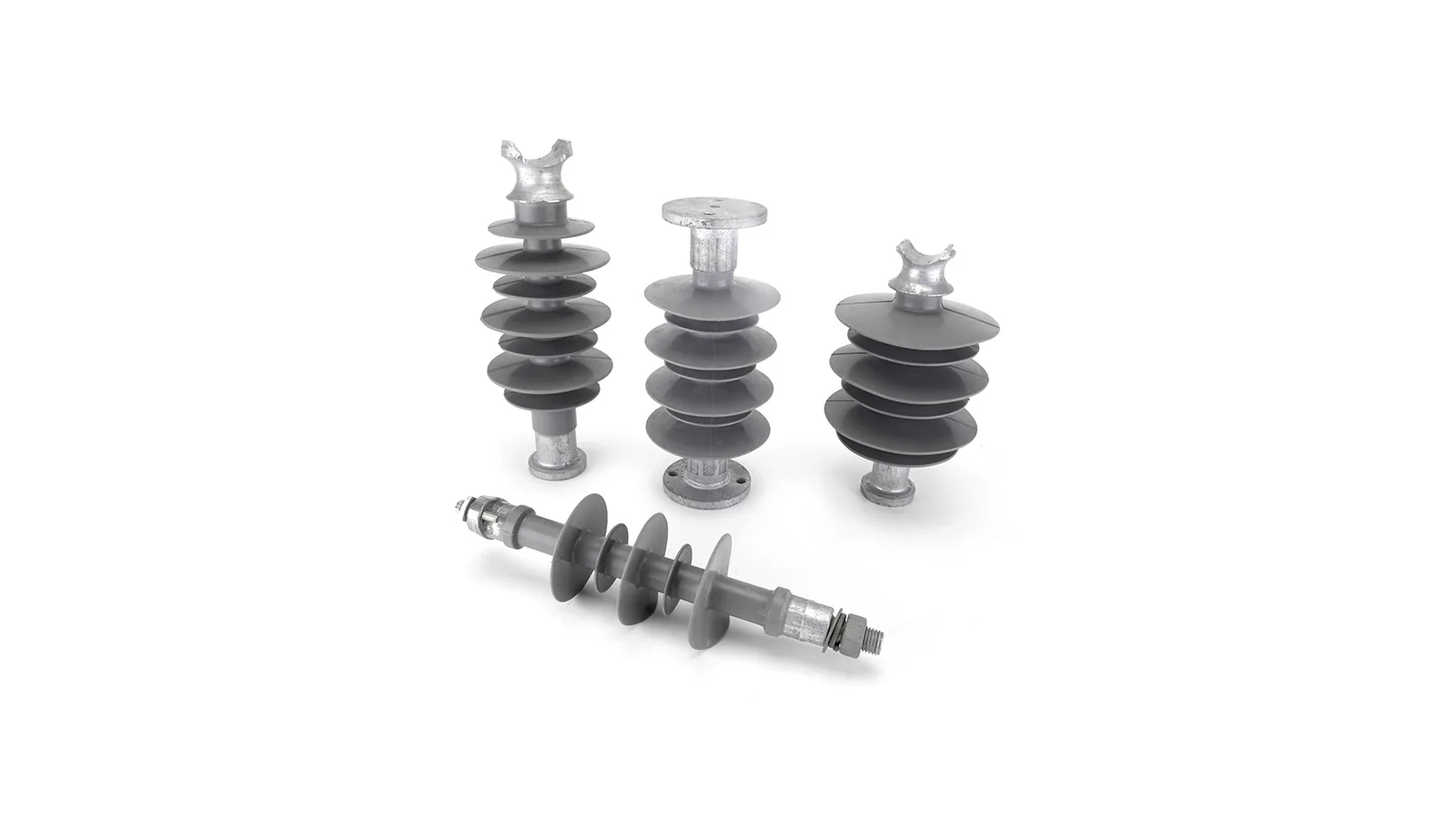
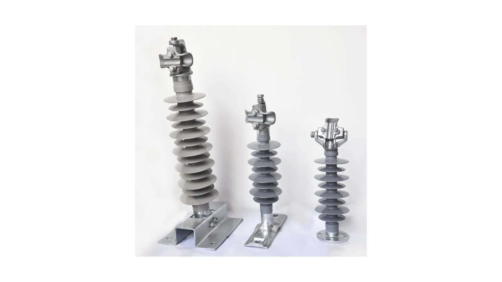
Composite pin insulator interface for 12-33 kV pin interface selection where spindle thread, shed profile and pollution duty decide the final model.
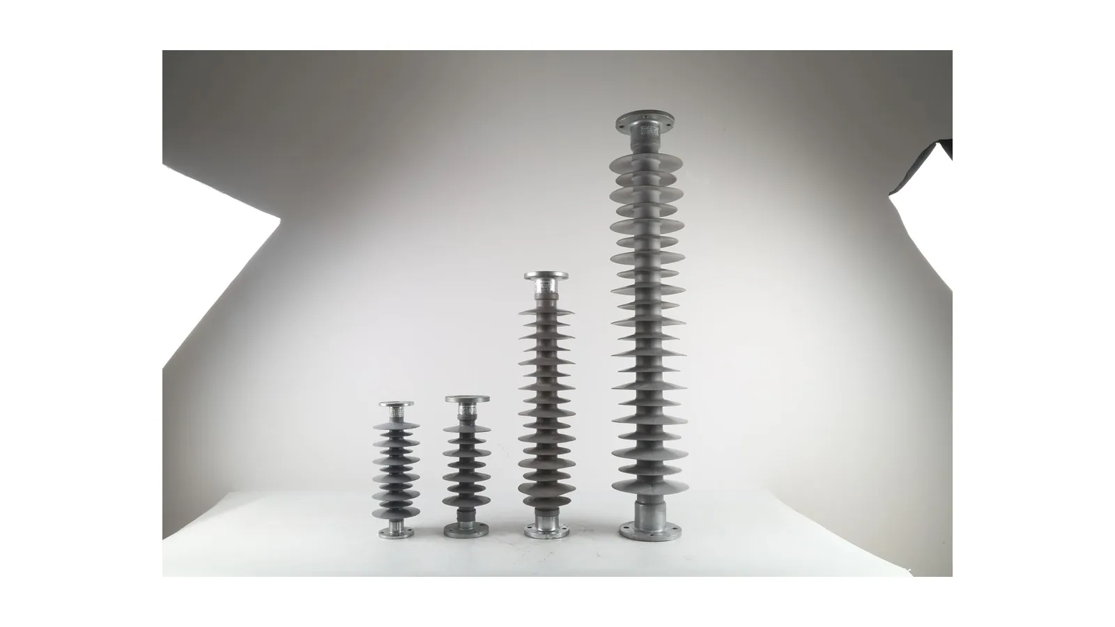
Composite post insulator interface for station post or equipment support duty where cantilever and bending duty are more important than suspension tensile rows.
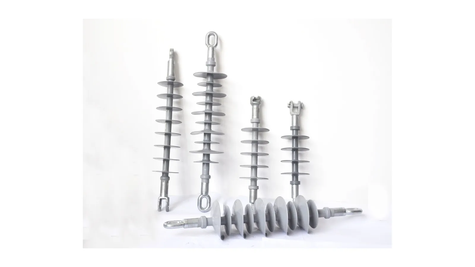
Composite suspension insulator interface for overhead line tension and suspension strings where FXB and FXBW rows separate voltage, SML and creepage requirements.
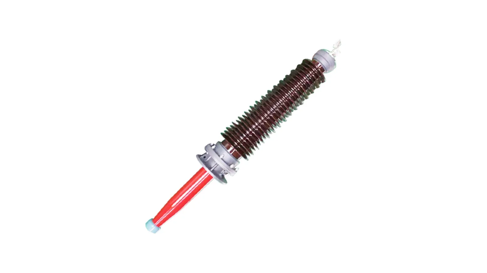
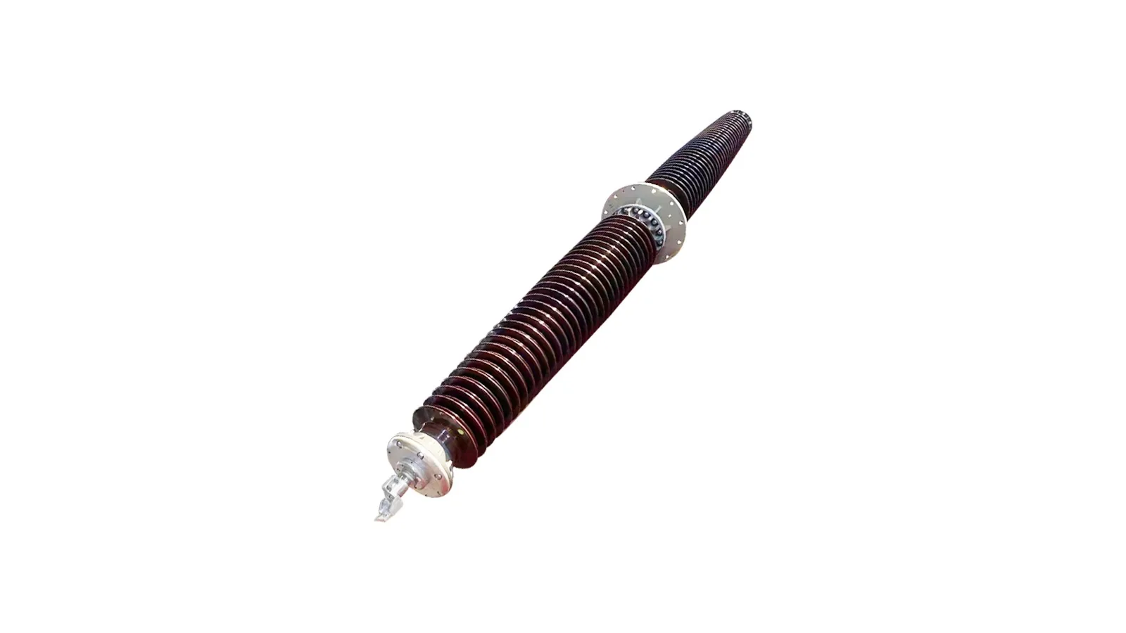
RIP transformer bushing interface for transformer tank interface duty where oil side, air side, conductor and flange data must be released as a matched set.
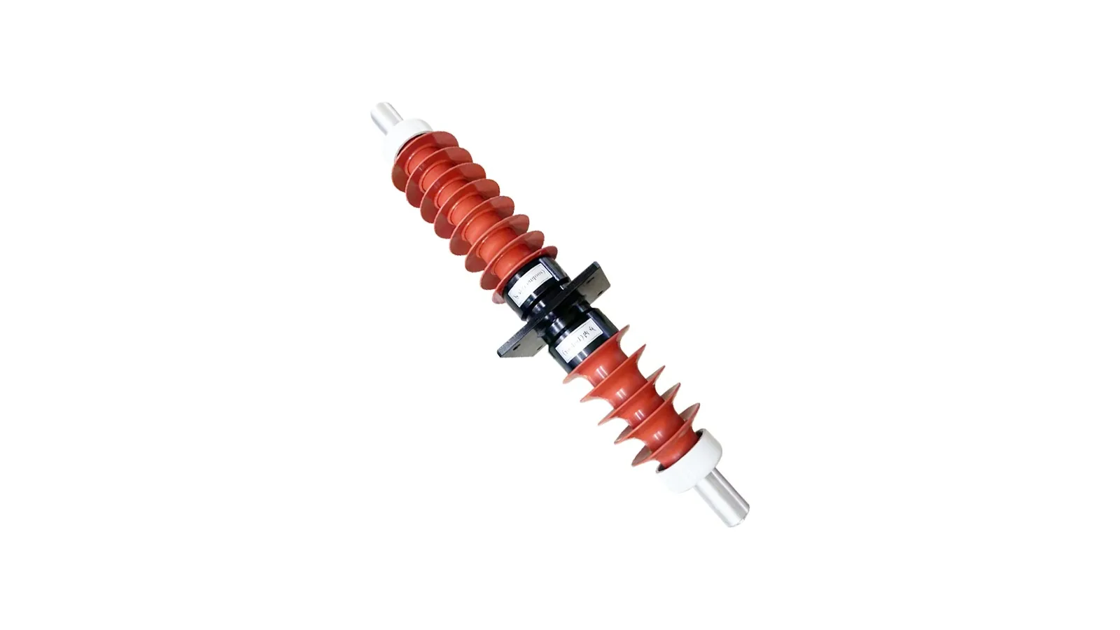
FCRG wall bushing interface for indoor and outdoor wall interface selection with dry capacitive insulation and silicone-rubber outer sheds.
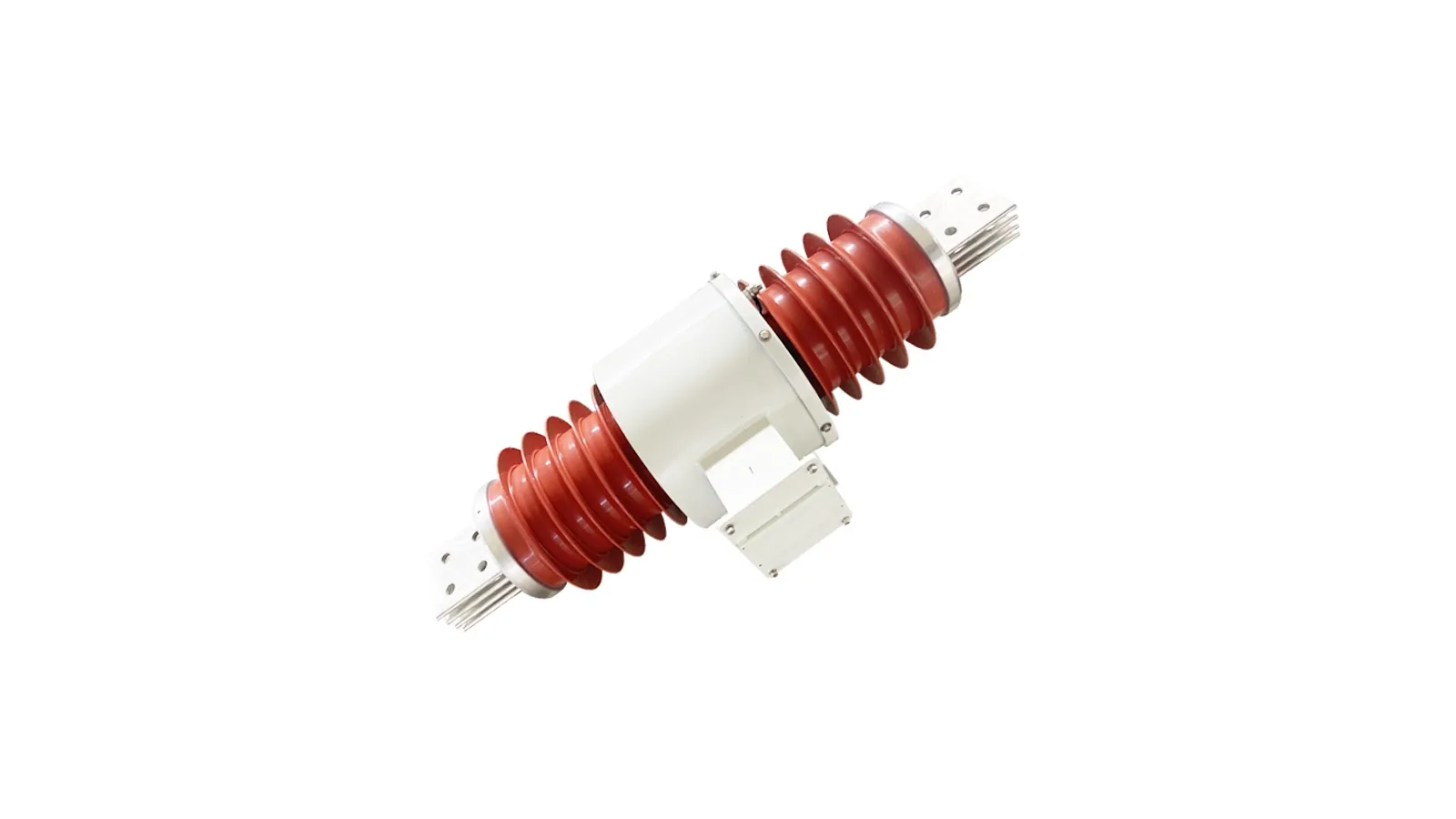
Dry composite wall bushing with current transformer interface where the conductor interface and CT secondary winding must be confirmed as separate electrical functions.
Dry porcelain wall bushing interface for capacitive main insulation with porcelain coat where porcelain construction must not be mixed with silicone-rubber wall bushing rows.
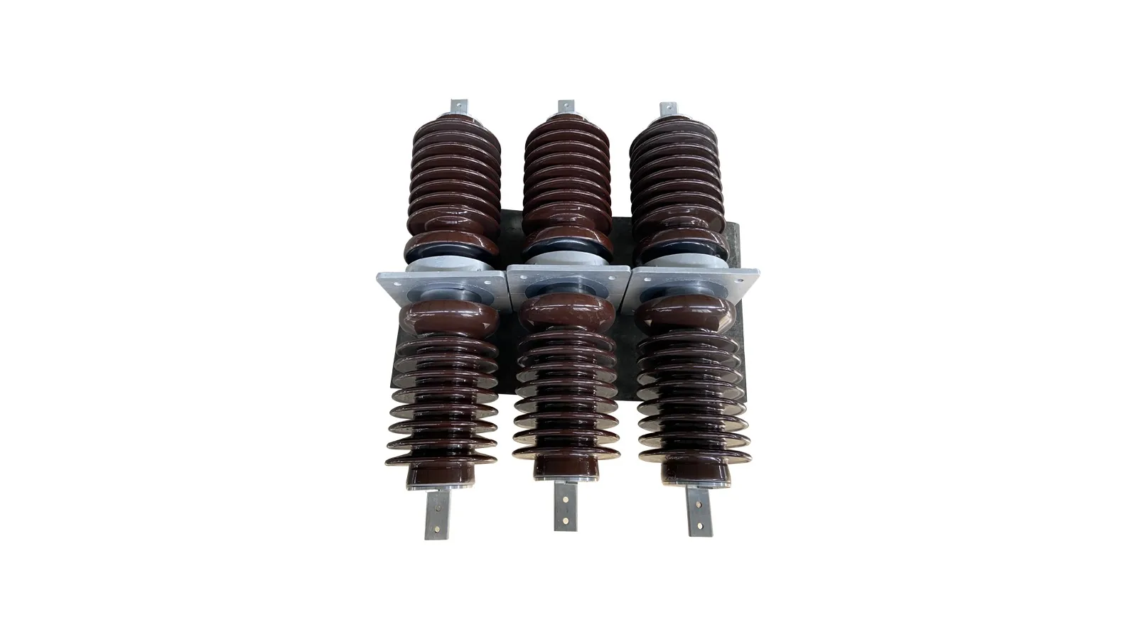
CWW wall bushing interface for porcelain wall interface selection where project conditions decide whether pure porcelain or dry capacitive construction is required.
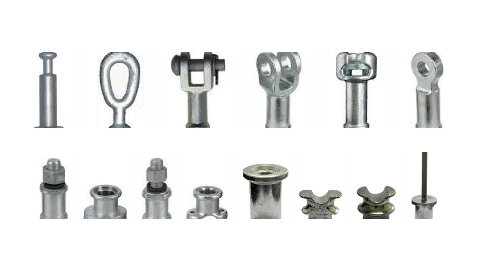
Composite insulator accessories interface for fittings and end hardware selection after the main insulator interface is already known.
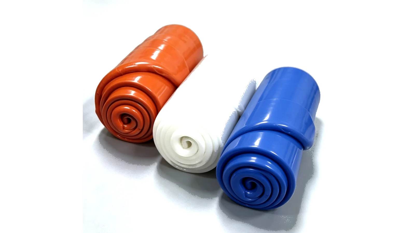
HTV silicone rubber compound option for composite insulator sheds, housings, insulation sheath and spacer material where hydrophobicity, tracking resistance, dielectric data and molding process must be confirmed.
The first question is not model number. It is where the insulator sits: overhead line support, suspension string, wall pass-through, transformer tank interface, silicone-rubber material use or hardware package.
Separate conductor support, tensile string duty, conductor pass-through and hardware fit before comparing model rows.
Use these interfaces when the conductor support interface and mechanical load decide the interface.
Use this interface when SML, end fitting and string duty define the order boundary.
Start from the bushing interface: FCRG dry composite wall, CCRG ceramic wall, FCRG-L CT wall and RIF transformer bushing interfaces need separate wall, tank, flange and conductor checks.
Use accessories only after the main insulator type and interface load are known.
Use the silicone rubber compound interface when grade code, color, hardness, tensile strength, hydrophobicity, tracking class and packaging need to be confirmed as material data.
Choose the product option by interface duty first, then keep each rating row inside the matching option.
Composite insulator selection depends on load duty and insulation duty: fiberglass core or capacitive insulation, silicone housing or porcelain coat, metal fitting or flange, and the conductor or support interface.
Confirm which part of the assembly carries load and which part defines insulation duty.
Do not reuse one product type’s values for another option. Each product option separates listed values from order-sheet checks.
Support load, bracket interface and creepage data decide which line-support row applies.
FCRG, CCRG, FCRG-L and RIF interfaces need separate voltage, current, flange, wall or tank interface and conductor data.
Use rating tables for listed values, product images for type identity, and drawing views only where dimensions support mounting, wall opening, flange or fitting checks.


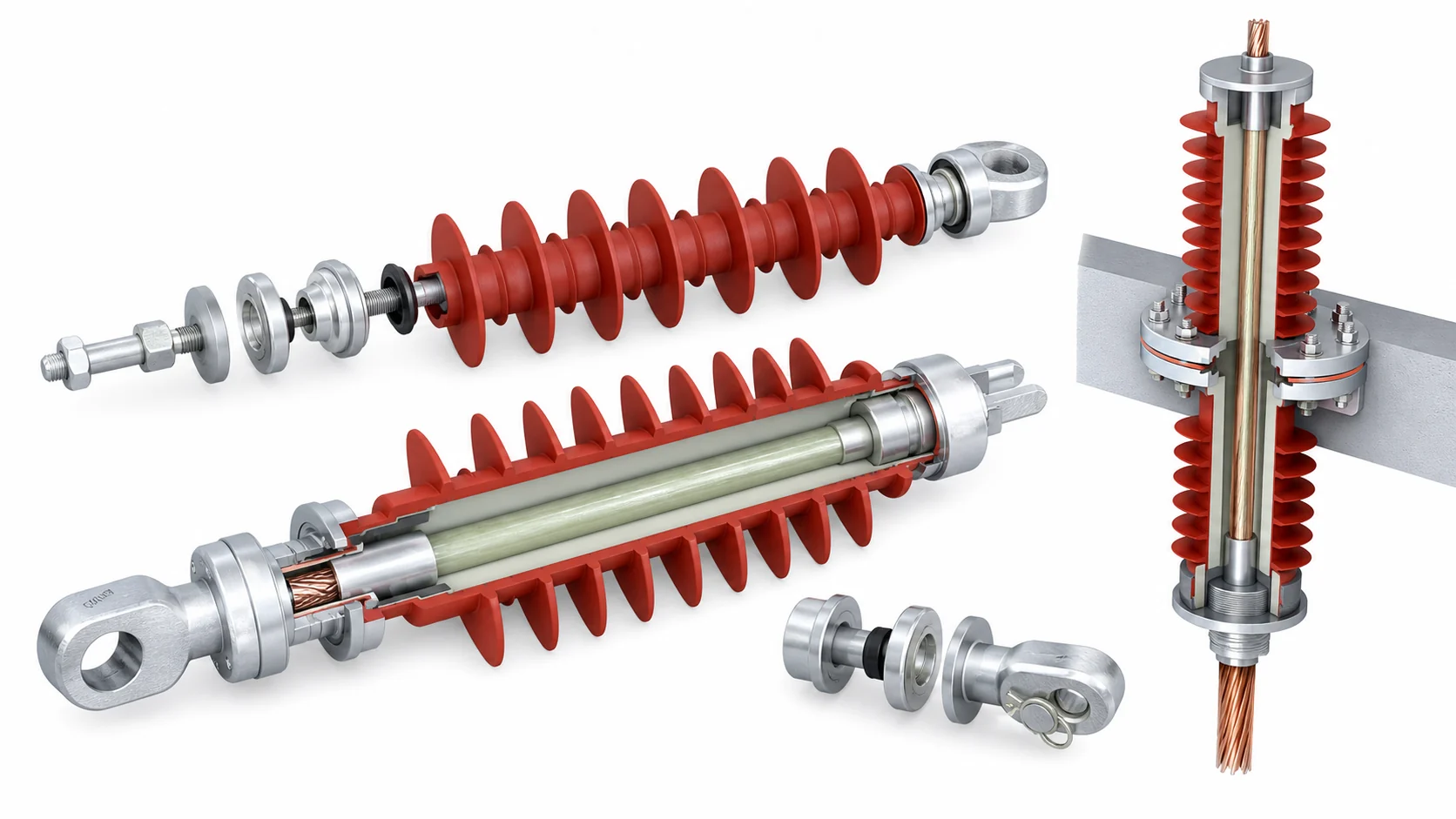
Product images help distinguish crossarm, line support, suspension, bushing, silicone rubber compound and accessory interfaces.
CI-05 includes FXB and FXBW outline views; download composite insulator catalog PDFs before confirming dimensions for other interfaces.
Crossarm, suspension and bushing values stay inside the selection option where they were listed.
Use FCRG, FCRG-L, CCRG, RIF and porcelain wall rows only with their matching wall, tank, flange, conductor or CT interface.
Confirm type, duty, interface and dimension evidence in that order so quotation data stays tied to the selected product option.
Crossarm, horizontal line, pin, post, suspension, bushing, silicone rubber compound or accessory interface.
Use tensile, cantilever, voltage, current or flange duty as appropriate.
End fittings, bracket, flange, conductor and wall opening decide the final package.
Use the suspension drawing view where it applies; request outlines for other interfaces if fixed dimensions matter.
Send the selected insulator type, voltage class, creepage distance, mechanical load, fitting or flange interface, dimension requirement, quantity and destination standard.
They are used for line support, suspension strings, conductor pass-through points, transformer tank interfaces, wall bushings, silicone-rubber material needs and accessory hardware packages.
Start from the installation interface and mechanical duty. Pin and post units support conductors or equipment, suspension units carry tensile string duty, and bushings pass a conductor through wall or tank insulation.
Use drawings when mounting holes, wall openings, flange dimensions, end fittings, tank interface or fixed length must be confirmed before production.
No. Suspension SML data describes tensile string duty. Post insulator support needs cantilever, bending and flange data from the matching model row or project sheet.
No. Fittings confirm hardware fit and mechanical connection. Electrical class, creepage distance, current and insulation duty must come from the selected insulator or bushing data.
Send the selected option, voltage or current row, mechanical duty, fitting or flange interface, fixed dimension requirement and quantity. XIYA will confirm the matching product option, rating boundary and document list.