Surge arrester product category

Surge Arresters for Line, Station, Low Voltage and Monitoring Options

Use this selector to separate line arresters, station arresters, low-voltage surge arresters, cut-out combinations, JCQ monitors, JS-8 counters, JSZ-8 indicators and PV counter options before confirming voltage duty, MCOV, discharge current, housing, mounting and drawing status.

Product types

Surge Arrester Types

Start with where the device will be installed, then compare the matching product type by voltage duty, mounting interface, monitoring function and drawing availability.
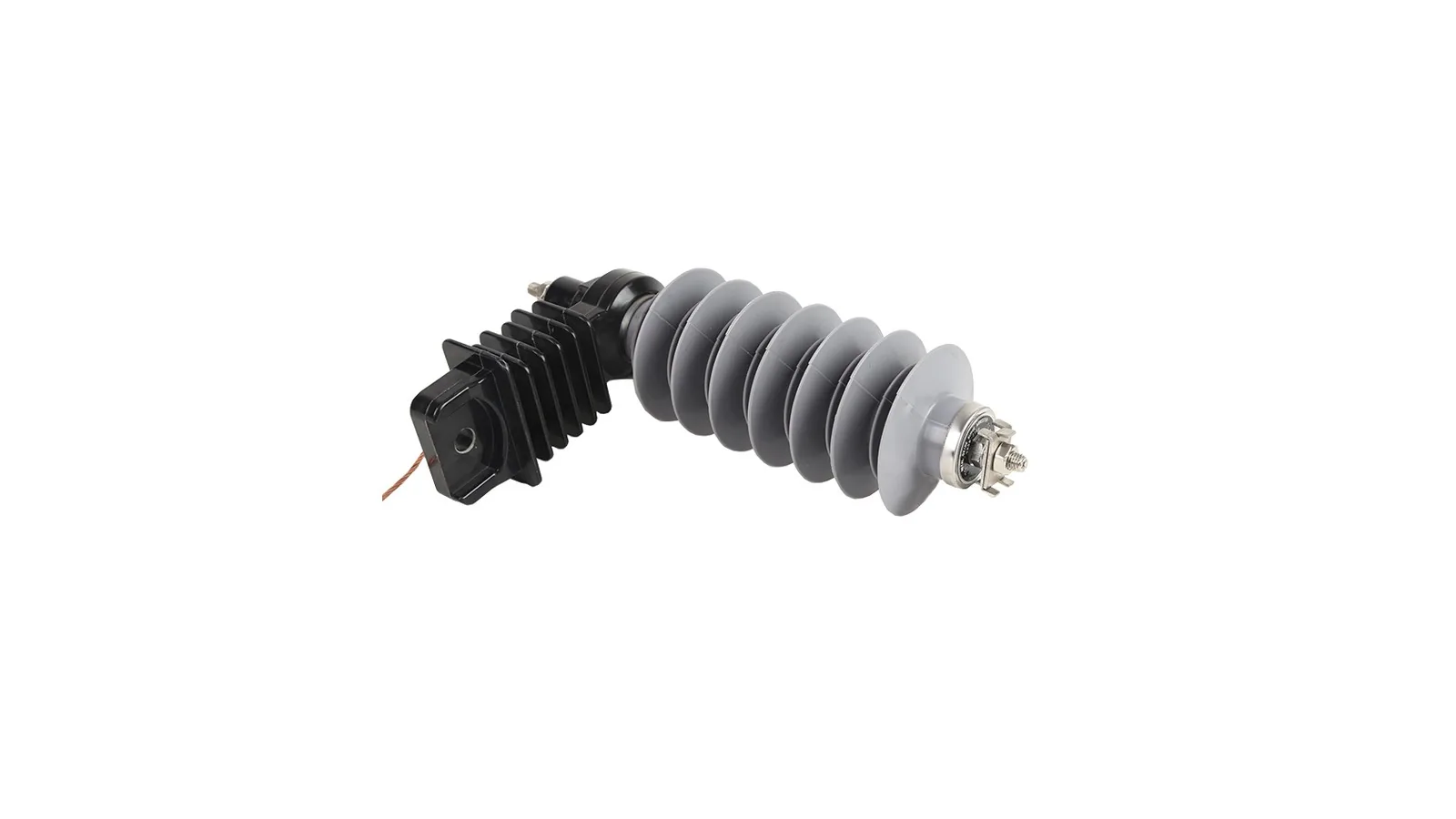
Distribution line surge arrester product on clean white background
SA 01Line arrester

Distribution Line Surge Arrester

Line type surge arrester path for overhead distribution feeder protection where the MOV column, polymer housing, bracket and earthing lead must match the feeder insulation duty.
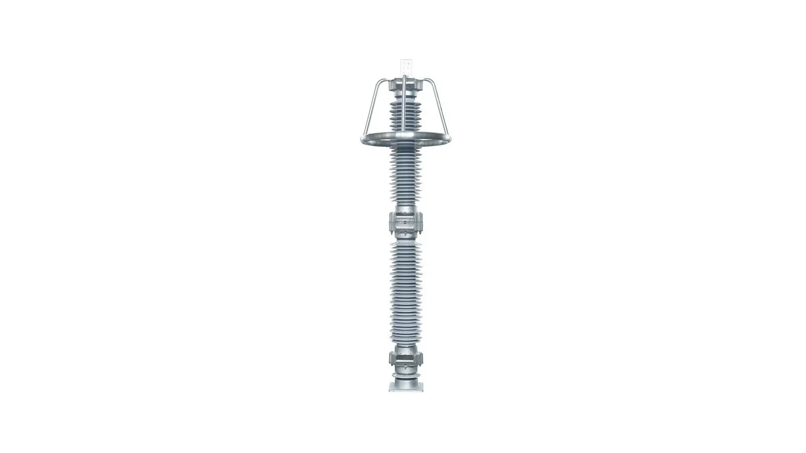
Station type surge arrester product on clean white background
SA 02Station arrester

Station Type Surge Arrester

Station type surge arrester path for substation bay protection where higher insulation coordination, base fitting and station grounding must be checked together.
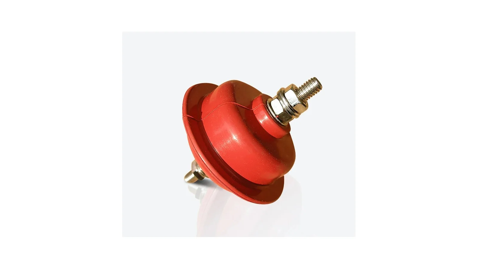
Low voltage surge arrester product on clean white background
SA 03LV arrester

Low Voltage Surge Arrester

Low Voltage surge arrester path for service entrance, low-voltage panel or downstream auxiliary protection where pole count and AC/DC system type decide the selected device.
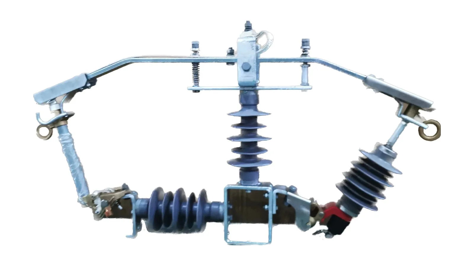
Cut out surge arrester combination assembly on clean white background
SA 04Cut-out combo

Cut Out Surge Arrester Combination

Combi cut-out and surge arrester path for pole-mounted fuse cutout assemblies where protection and overvoltage clamping are packaged in one feeder branch arrangement.
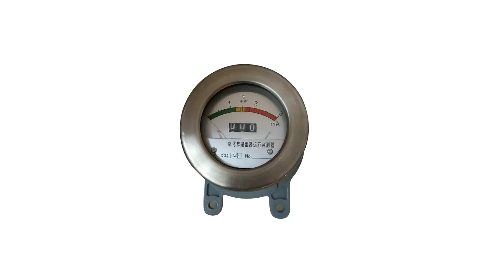
JCQ surge arrester monitor product on clean white background
SA 06JCQ monitor

JCQ Surge Arrester Monitor

JCQ monitor path for online leakage-current observation and arrester operation counting across multiple high-voltage classes.
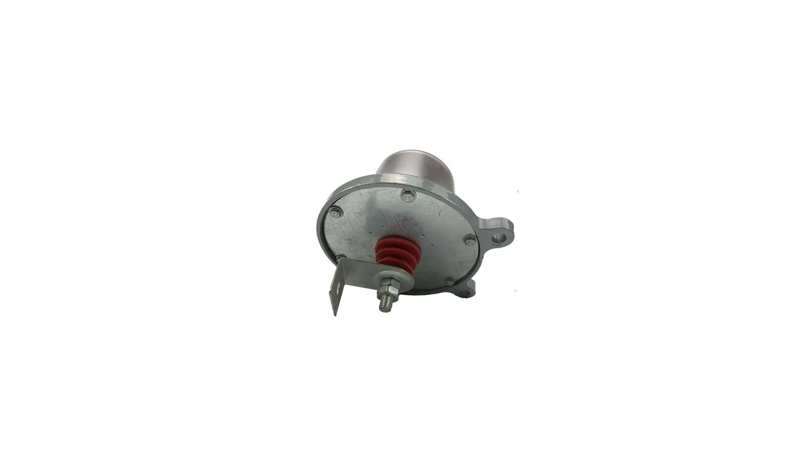
JS-8 surge arrester counter product on clean white background
SA 07JS-8 counter

JS-8 Surge Arrester Counter

JS-8 counter path for recording arrester discharge operations on the grounding side below the arrester.
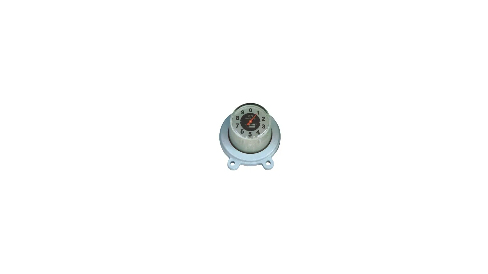
JSZ-8 surge arrester counter with indicator product on clean white background
SA 08JSZ-8 indicator

JSZ-8 Surge Arrester Counter with Indicator

JSZ-8 counter with indicator path where the base counter function is combined with visible power or fault indication.
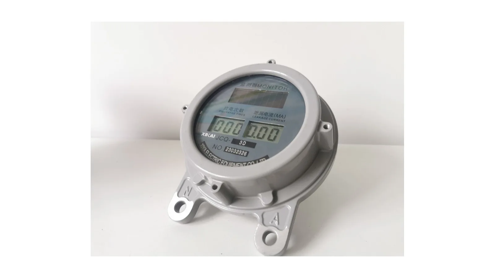
Photovoltaic surge arrester counter product on clean white background
SA 09PV counter

Photovoltaic Surge Arrester Counter

PV arrester counter path for solar station monitoring where the device is installed between surge arrester and earth and the PV station package decides final wiring.

Technical parameters

Distribution Line Surge Arrester selection boundary

Line type surge arrester path for overhead distribution feeder protection where the MOV column, polymer housing, bracket and earthing lead must match the feeder insulation duty.

Reference basisUse for overhead feeder protection when feeder voltage, MCOV, nominal discharge current, creepage and bracket interface are known
Distribution line surge arrester product on clean white background
Distribution Line Surge Arrester product view
Library code
DE04-SA-01
Product type
Line type surge arrester
Selection option
Core distribution feeder arrester option
Application point
Overhead distribution feeder, pole line or transformer branch entry
Selection basis
Overhead feeder position, voltage duty, discharge current, creepage distance and bracket interface
Service conditions
English MOSA document lists -55 to +50 deg C ambient, altitude no more than 2000 m, 48-62 Hz supply, wind speed no more than 35 m/s and earthquake intensity no more than 7
Standards basis
Technical performance row references IEC 60099-4, IEEE C62.11 and GB 11032
Drawing request
Request an outline drawing with the RFQ when pole bracket spacing or overall height must be checked
Main components
MOV column and polymer housing with line terminal, bracket interface and earth lead
System role
Limit lightning and switching overvoltage from conductor to earth before downstream equipment insulation is overstressed
Rating data boundary
Use the order sheet for rated voltage, continuous operating voltage, nominal discharge current, creepage distance and bracket type
What to confirm
Confirm rated voltage, continuous operating voltage, discharge current, creepage distance and bracket interface
RFQ checks
Confirm feeder voltage, grounding arrangement, pollution grade, altitude, bracket, disconnector need and counter need

Distribution Line Surge Arrester selection rows

Selection fieldSelection valueEngineering check
Selection optionDistribution line surge arresterCore feeder option
Visible equipmentPolymer housed zinc oxide arrester with line terminal and mounting hardwareMatch with the requested feeder installation
Application pointOverhead feeder and distribution transformer branch protectionConfirm from project single-line diagram
Standards and site conditionIEC 60099-4, IEEE C62.11, GB 11032, -55 to +50 deg C, altitude <=2000 m, 48-62 HzConfirm against final order sheet
Rating dataProject sheet required for exact voltage, MCOV, discharge current and creepage valueDo not infer from visual similarity
Drawing needRequest outline dimensions when bracket spacing or total height mattersAttach pole hardware details
Selection note

Use this product type for initial selection. If a value is not listed for this option, confirm it from the project sheet before quotation.

Technical parameters

Station Type Surge Arrester selection boundary

Station type surge arrester path for substation bay protection where higher insulation coordination, base fitting and station grounding must be checked together.

Reference basisUse for substation bay protection when insulation level, arrester class, creepage and base fitting are known
Station type surge arrester product on clean white background
Station Type Surge Arrester product view
Library code
DE04-SA-02
Product type
Station type surge arrester
Selection option
Substation and high-voltage arrester option
Application point
Substation bay, transformer station, incoming or outgoing line bay
Selection basis
Substation position, insulation level, arrester class, creepage distance and base fitting
Drawing request
Request an outline drawing with the RFQ when terminal height, base hole spacing or station layout must be checked
Main components
MOV stack, station housing, top terminal, base fitting and earth connection
System role
Clamp overvoltage at station equipment terminals and discharge surge current to the grounding grid
Rating data boundary
Station insulation level, line discharge class and creepage distance must come from project values
What to confirm
Confirm voltage class, station insulation level, line discharge class and base fitting
RFQ checks
Confirm rated voltage, MCOV, nominal discharge current, pressure relief class, creepage, base interface and grounding point

Station Type Surge Arrester selection rows

Selection fieldSelection valueEngineering check
Selection optionStation type surge arresterSubstation bay option
Visible equipmentStation arrester body with vertical terminal structureMatch with bay equipment layout
Application pointHigh-voltage station equipment protectionCoordinate with transformer, bus and line equipment
Rating dataProject sheet required for voltage, insulation level and arrester classDo not reuse line arrester values
Drawing needRequest outline dimensions when terminal height or base fitting mattersAttach bay layout if available
Selection note

Use this product type for initial selection. If a value is not listed for this option, confirm it from the project sheet before quotation.

Technical parameters

Low Voltage Surge Arrester selection boundary

Low Voltage surge arrester path for service entrance, low-voltage panel or downstream auxiliary protection where pole count and AC/DC system type decide the selected device.

Reference basisUse for LV panel or service-entry protection when AC/DC system type, pole count and protection class are known
Low voltage surge arrester product on clean white background
Low Voltage Surge Arrester product view
Library code
DE04-SA-03
Product type
Low Voltage surge arrester
Selection option
LV protection option
Application point
LV panel, service entrance, auxiliary distribution cabinet or control supply option
Selection basis
LV circuit type, AC/DC option, pole count, protection class and installation base
Drawing request
Request dimensions if the arrester must fit a fixed panel or rail space
Main components
Compact arrester body, connection terminals and mounting base
System role
Limit transient overvoltage on low-voltage AC/DC circuits before terminal equipment is exposed
Rating data boundary
AC/DC system, pole count, protection class and coordination level must come from the order sheet
What to confirm
Confirm AC/DC system, pole count and protection class
RFQ checks
Confirm system voltage, phase or pole count, installation rail or base, protection class, backup fuse and quantity

Low Voltage Surge Arrester selection rows

Selection fieldSelection valueEngineering check
Selection optionLow Voltage surge arresterLV option
Visible equipmentCompact LV arrester body with terminal interfaceConfirm panel space and wiring direction
Application pointLV panel or service entrance transient protectionConfirm cabinet and circuit type
Rating dataProject sheet required for voltage, pole count and protection classDo not inherit MV arrester data
Selection note

Use this product type for initial selection. If a value is not listed for this option, confirm it from the project sheet before quotation.

Technical parameters

Cut Out Surge Arrester Combination selection boundary

Combi cut-out and surge arrester path for pole-mounted fuse cutout assemblies where protection and overvoltage clamping are packaged in one feeder branch arrangement.

Reference basisUse for pole-mounted fused protection when fuse cutout rating, arrester voltage, bracket angle and grounding lead are known
Cut out surge arrester combination assembly on clean white background
Cut Out Surge Arrester Combination product view
Library code
DE04-SA-04
Product type
Combi cut-out and surge arrester
Selection option
Combined fuse cutout with arrester branch option
Application point
Pole-mounted transformer branch, distribution feeder tap and fused protection point
Selection basis
Fuse cutout rating, arrester voltage, bracket spacing, mounting angle and grounding lead
Drawing request
Request an assembly outline when pole hardware spacing, fuse angle or grounding option must be checked
Main components
Fuse cutout, arrester branch, mounting bracket, upper and lower terminal hardware
System role
Combine fuse isolation and surge discharge path in one pole-mounted branch assembly
Rating data boundary
Do not reuse as a standalone drop-out fuse rating row; arrester and fuse package must be confirmed together
What to confirm
Fuse cutout rating, arrester voltage, bracket spacing, mounting angle and grounding lead
RFQ checks
Confirm system voltage, fuse link, arrester class, bracket, insulator option, pole hardware and quantity

Cut Out Surge Arrester Combination selection rows

Selection fieldSelection valueEngineering check
Selection optionCut out surge arrester combinationCombined protection option
Visible equipmentFuse cutout assembly with parallel arrester branch and bracket hardwareMatch with pole hardware and fuse-link plan
Application pointTransformer branch or feeder tap with fuse and surge protectionConfirm with pole hardware sheet
BoundaryDo not reuse as a standalone drop-out fuse rating rowFuse and arrester package must match
Selection note

Use this product type for initial selection. If a value is not listed for this option, confirm it from the project sheet before quotation.

Technical parameters

JCQ Surge Arrester Monitor selection boundary

JCQ monitor path for online leakage-current observation and arrester operation counting across multiple high-voltage classes.

Reference basisUse for leakage-current monitoring and operation-count selection when voltage class, JCQ suffix and alarm-output need are known
JCQ surge arrester monitor product on clean white background
JCQ Surge Arrester Monitor product view
Library code
DE04-SA-06
Product type
JCQ surge arrester monitor
Selection option
Accessory monitor option
Application point
Series position between surge arrester grounding side and earth
Selection basis
Voltage class, JCQ suffix, alarm-output need, leakage-current scale and grounding-lead position
Drawing data
Drawing tab provides the JCQ-C4 structure and dimension view for mounting review
Accessory relationship
Use this JCQ product row when the counter and monitor option needs leakage-current monitoring plus operation count
Model range
JCQ1-10/600, JCQ1-10/800, JCQ1-10/1000, JCQ1-20/1500 and JCQ1-20/2000
Voltage coverage
JCQ1-10/600 for 6-110 kV; JCQ1-10/800 for 110-220 kV; JCQ1-10/1000 for 350 kV; JCQ1-20/1500 and JCQ1-20/2000 for 500 kV
Function
Monitor leakage current change and record arrester operation count
Structure
Nonlinear resistor, electromagnetic counter, milliampere meter, relay and electronic components in the JCQ1 monitor document
Service condition
Altitude no more than 3000 m; ambient temperature -40 to +40 deg C in the English document
Drawing data
JCQ-C4 drawing shows 139 mm face diameter, 86 +/-2 mm mounting-hole spacing and 183 mm body depth
Installation boundary
Use in the arrester grounding lead and confirm meter visibility before quotation
What to confirm
Model code, alarm output, leakage current scale, rated discharge current and installation position
RFQ checks
Confirm voltage class, JCQ suffix, alarm output, meter scale, grounding lead, testing method and quantity

JCQ Surge Arrester Monitor selection rows

Model rowListed valuesEngineering check
JCQ1-10/6006-110 kVUse only for JCQ monitor option
JCQ1-10/800110-220 kVUse only for JCQ monitor option
JCQ1-10/1000350 kVUse only for JCQ monitor option
JCQ1-20/1500 / JCQ1-20/2000500 kVUse only for JCQ monitor option
Function rowLeakage current monitoring and operation countAccessory function, not arrester rating
Service rowAltitude <=3000 m; ambient -40 to +40 deg CConfirm site condition
Selection note

Use this product type for initial selection. If a value is not listed for this option, confirm it from the project sheet before quotation.

JCQ-C4 monitor structure and dimension drawing with 139 mm face diameter and 86 +/-2 mm mounting-hole spacing
Technical parameters

JS-8 Surge Arrester Counter selection boundary

JS-8 counter path for recording arrester discharge operations on the grounding side below the arrester.

Reference basisUse for discharge-count selection below the arrester when counter model, voltage class and grounding-lead mounting are known
JS-8 surge arrester counter product on clean white background
JS-8 Surge Arrester Counter product view
Library code
DE04-SA-07
Product type
JS-8 surge arrester counter
Selection option
Accessory counter option
Application point
Accessory path below the arrester grounding side
Selection basis
Counter model, voltage class, discharge-current row, grounding-lead mounting and test requirement
Drawing data
Drawing tab provides JS-8 installation and structure dimension views for mounting review
Accessory relationship
Use this JS-8 product row when the project needs discharge operation counting below the arrester
Model range
JS-8 and JS-8A
Voltage coverage
JS-8 for 6-220 kV; JS-8A for 330 kV and above
Voltage note
Older JS-8 records include a 3-220 kV start while the English JS-8 page lists 6-220 kV; confirm the final model sheet before quotation
Impulse row
8/20 us nominal discharge current row appears in the document set
Square wave row
2 ms square wave current appears in the JS-8 data rows
Structure
Valve element, silicon bridge rectifier, capacitor and electromagnetic counter in the English document
Service condition
Altitude no more than 4000 m; ambient temperature -40 to +40 deg C in the English JS-8 document
Drawing data
JS-8 drawings show 130 mm face diameter, 86 mm mounting-hole spacing, 2 x 10.5 mm mounting holes and 10 mm arrester terminal
Function
Record frequency of arrester operation
What to confirm
JS-8 or JS-8A, voltage class, mounting position, counter window and test requirement
RFQ checks
Confirm counter model, voltage class, discharge current row, grounding lead, mounting hardware and quantity

JS-8 Surge Arrester Counter selection rows

Model rowListed valuesEngineering check
JS-86-220 kVAccessory counter only
JS-8A330 kV and aboveAccessory counter only
Impulse row8/20 us document rowConfirm exact current before final selection
Current row2 ms square wave current appears in JS-8 dataUse with matching model
Function rowRecord arrester operation countDoes not define arrester protection level
Selection note

Use this product type for initial selection. If a value is not listed for this option, confirm it from the project sheet before quotation.

JS-8 counter installation dimension drawing with 130 mm face diameter and 86 mm mounting spacing
JS-8 counter structure dimension drawing with terminal and mounting details
Technical parameters

JSZ-8 Surge Arrester Counter with Indicator selection boundary

JSZ-8 counter with indicator path where the base counter function is combined with visible power or fault indication.

Reference basisUse when discharge counting must be combined with visible power or arrester-fault indication
JSZ-8 surge arrester counter with indicator product on clean white background
JSZ-8 Surge Arrester Counter with Indicator product view
Library code
DE04-SA-08
Product type
JSZ-8 counter with indicator
Selection option
Accessory counter with indicator option
Application point
Arrester grounding side where discharge count plus indication is required
Selection basis
Indicator need, counter range, alarm function, wiring option, mounting and grounding path
Drawing request
Request dimensions with the RFQ if the JSZ-8 indicator must match a fixed panel or bracket location
Function
Counter with indicator function added on the discharge counter base
Indicator note
Adds power-visible and arrester-fault indication on the discharge counter base
Counter row
JS-8 counter data is a screening basis for the counter accessory group; confirm suffix, indicator need and wiring before quotation
Service condition
Shared English JS document lists altitude no more than 4000 m and ambient temperature -40 to +40 deg C
Data limit
The indicator does not replace arrester selection
What to confirm
Indicator need, counter range, alarm function, mounting and grounding path
RFQ checks
Confirm JSZ-8 suffix, indicator requirement, voltage class range, wiring, test method and quantity

JSZ-8 Surge Arrester Counter with Indicator selection rows

Selection fieldSelection valueEngineering check
Selection optionJSZ-8 counter with indicatorAccessory indicator option
Function rowCounter plus indicator functionConfirm final indicator requirement
BoundaryDoes not replace arrester selectionMatch with selected arrester path
Data to confirmSuffix, voltage class range, wiring and mountingRequired before quotation
Selection note

Use this product type for initial selection. If a value is not listed for this option, confirm it from the project sheet before quotation.

Technical parameters

Photovoltaic Surge Arrester Counter selection boundary

PV arrester counter path for solar station monitoring where the device is installed between surge arrester and earth and the PV station package decides final wiring.

Reference basisUse for PV station arrester monitoring when power option, grounding position, outdoor sealing and inspection method are known
Photovoltaic surge arrester counter product on clean white background
Photovoltaic Surge Arrester Counter product view
Library code
DE04-SA-09
Product type
PV arrester counter and monitor option
Selection option
Photovoltaic monitoring accessory option
Application point
Solar station arrester grounding side and outdoor PV protection option
Selection basis
PV station voltage option, monitor type, power supply option, grounding point, sealing and inspection method
Drawing data
Drawing tab provides the outline installation and dimension view for JCQ-3D mounting review
Installation role
Series between surge arrester and earth
Testing note
The PDF describes periodic monitoring before running or after 1-2 years
Inspection method
Measure DC resistance between H.V. lead terminal and earth; no short circuit, open circuit or poor contact
Action test
1000 V megohmmeter charges a 1200 V, 1 uF capacitor; 10 consecutive operations should act correctly before acceptance
Mounting note
Flange fixed by M10 x 30 bolts near the arrester base; H.V. down-lead pull not more than 10 kg
Factory test basis
JCQ-D test report references JB/T10492 monitoring devices for metal-oxide surge arresters
Terminal note
High-voltage terminal down-lead pull is limited to 10 kg in the instruction text
Data limit
PV monitor does not set the arrester voltage class
What to confirm
PV monitor type, power supply option, counter function, outdoor sealing and grounding path
RFQ checks
Confirm PV station voltage, monitor type, wiring, grounding point, test method, enclosure option and quantity

Photovoltaic Surge Arrester Counter selection rows

Selection fieldSelection valueEngineering check
Selection optionPV arrester countersolar station monitoring option
Installation rowseries between surge arrester and earthUse with selected PV arrester option
Inspection rowMonitor before running or after 1-2 years in the instruction textProject maintenance note
Terminal rowHigh-voltage terminal down-lead pull not more than 10 kgInstallation check
BoundaryPV monitor does not set arrester voltage classConfirm from PV project sheet
Selection note

Use this product type for initial selection. If a value is not listed for this option, confirm it from the project sheet before quotation.

Photovoltaic counter outline installation and dimension drawing with JCQ-3D mounting dimensions
Application fit

Surge Arrester Applications

The placement question comes first: overhead feeder, substation bay, LV cabinet, fuse cutout assembly, grounding-side counter or PV station monitor. Add the DE04-SA-05 counter accessory group only after the main arrester type is known.

Protection role

Surge current must have a controlled path from conductor to earth.

Separate overvoltage clamping duty from monitoring duty before choosing the final product type.

Arrester option

Line, station, LV and cut-out combination options

Use these rows when the device must clamp overvoltage and discharge surge current.

Monitoring option

DE04-SA-05 counter accessory group: JCQ, JS-8, JSZ-8 and PV options

Use these rows when the project needs operation count, leakage-current monitoring, visible indication or alarm output.

Grounding route

Earth lead, base fitting and counter connection

Confirm the grounding path, meter visibility and series installation position before selecting counter or monitor accessories.

Selection matrix

Surge Arrester Selection Matrix

Use the matrix to choose the correct product type before quotation: protection duty stays with arrester rows, while counting, monitoring and indication stay with accessory rows.

Decision option
Protection or monitoring role
Rating data
Distribution feeder optionLine arrester on overhead feeder or transformer branch
MOV column from conductor to earth
Confirm voltage, MCOV, discharge current and bracket
Substation optionStation type arrester at transformer, bus or line bay
Station grounding grid and insulation coordination
Confirm station insulation level, class and creepage
Low-voltage optionLV panel, service entrance or auxiliary cabinet
Compact arrester device by AC/DC circuit type
Confirm system, pole count and protection class
Combined cut-out optionFuse cutout plus arrester branch on pole hardware
Fuse protection plus overvoltage discharge path
Confirm fuse link, arrester voltage and bracket spacing
Monitoring optionDE04-SA-05 counter accessory group with JCQ, JS-8, JSZ-8 or PV counter below arrester
Counter, leakage-current monitor or indicator in the earthing lead
Confirm model, voltage range, alarm, test method and H.V. lead pull
Boundary optionAccessory data does not define arrester duty
Counter function stays separate from arrester protection rating
Confirm main arrester data from project sheet
Working principle

MOV Protection and Earthing Path

Use this sequence to separate arrester structure from monitor accessories: the MOV column clamps the surge, the housing and shed profile manage insulation, the disconnector or counter interface sits below the arrester, and the earthing path discharges current safely.

Structure checks

Confirm these elements before choosing the arrester type or adding a counter accessory.

MOV columnMetal-oxide blocks clamp transient overvoltage.
Housing and shed profilePolymer or station housing controls insulation distance.
Disconnector or counter interfaceAccessory boundary sits in the lower grounding path.
Earthing pathSurge current must discharge to the grounding system.
Rating boundary

Surge Arrester Ratings

Use arrester rows for voltage and surge-protection duty. Use counter and monitor rows only for counting, leakage-current monitoring, indication and grounding-side installation details.

Main arrester

Voltage, MCOV, discharge current and creepage stay with the selected arrester type.

Line, station, LV and cut-out combination rows cannot inherit each other’s rating data.

Accessory boundary

Counter and monitor rows define counting, monitoring, indication and alarm functions.

Do not use these accessory rows to set arrester voltage, MCOV or residual-voltage duty.

Line arresterFeeder voltage, MCOV and bracket interface

Confirm from feeder project sheet and site condition.

Station arresterStation insulation level and base fitting

Confirm bay equipment duty and grounding grid.

LV and cut-outPanel option or fused branch package

Keep LV protection data and fuse-combination data separate.

Monitoring accessoryJCQ, JS-8, JSZ-8 and PV counter options

Confirm model, voltage range, alarm output, test method and grounding-lead position.

Drawing and data

Drawings and Technical Documents

Drawing tabs help check dimensions and installation layout where a drawing is available; teams can also download surge arrester catalog PDFs before checking outline and mounting data. Voltage, MCOV, discharge current and creepage still need to come from the project sheet or order specification.

Mounting dimensions

Use drawing views for mounting checks

JCQ, JS-8 and PV counter options include drawing views for face diameter, hole spacing, terminal and mounting checks.

Rating values

Confirm electrical ratings from the project sheet

Do not infer voltage, MCOV, discharge current or creepage from product appearance or accessory drawings.

Dimension request

Request outline drawings when fixed dimensions matter

If line, station, LV, cut-out combination or JSZ-8 options need fixed dimensions, include an outline or mounting drawing request in the RFQ.

Installation checks

Use accessory instructions for mounting and testing

PV and JCQ counter instructions require series installation between arrester and earth, grounding before removal, repeated action testing and H.V. lead pull not more than 10 kg.

Engineering selection

Surge Arrester RFQ Data

Send the product type and system position first, then match voltage, discharge duty, housing, mounting and monitoring accessories, or check certificates, test reports and RFQ forms before quotation release.

01 / TypeSelect the product type

Line, station, LV, cut-out combination, or DE04-SA-05 counter accessory group for JCQ, JS-8, JSZ-8 and PV accessories.

02 / DutyMatch overvoltage or monitoring function

Clamp surge current for arrester options or count/monitor for accessory options.

03 / RatingUse the matching data row

Do not copy values across unrelated voltage classes or accessory groups.

04 / MountingFinalize from project sheet

Base, bracket, earth lead, counter position and site conditions decide the final package.

Product typeChoose line, station, LV, cut-out combination, JCQ, JS-8, JSZ-8 or PV counter option.
System voltageDistribution feeder, station, LV or PV project voltage.
MCOV and dutyContinuous operating voltage, discharge current and insulation coordination.
Housing optionPolymer, station housing, LV device body or cut-out combination package.
Mounting interfaceBracket, base fitting, pole hardware, panel interface or PV station enclosure.
Monitoring needCounter, leakage-current monitor, indicator, alarm output or PV monitor option under the DE04-SA-05 accessory group.
Site conditionsAltitude, pollution grade, grounding system and outdoor exposure.
Drawing needUse available drawing views; otherwise include the required outline or mounting drawing request in the RFQ.
FAQ

Surge Arrester FAQ

What surge arrester data is needed for RFQ?

Send product type, system voltage, MCOV or continuous operating voltage, nominal discharge current, creepage or pollution grade, housing option, bracket or base fitting, counter or monitor requirement, grounding path, site conditions and quantity.

Where is a surge arrester used?

Use a surge arrester where lightning or switching overvoltage must be clamped on an overhead feeder, substation bay, LV cabinet, fuse cutout branch or PV station protection point.

When should engineers choose the product type before the model?

Choose the product type first when line, station, low-voltage, cut-out combination, JCQ, JS-8, JSZ-8 or PV counter options are still being compared. The model should follow system position, voltage duty, mounting interface and monitoring function.

When are surge arrester Drawing tabs available?

Drawing tabs appear only when a matching drawing image or drawing page is available for that product type. If no Drawing tab appears, include the outline or mounting drawing request with the RFQ.

Can counter or monitor data define arrester ratings?

No. JCQ, JS-8, JSZ-8 and PV counters are monitoring accessories. Arrester voltage, MCOV, residual-voltage and discharge-current data must come from the selected arrester option and project sheet.

How should engineers choose between line and station arresters?

Start from system position. Use line arresters for overhead distribution feeders and station arresters for substation bay or transformer station insulation coordination.

Request Surge Arrester Quote

Send the product type, system voltage, continuous operating voltage, nominal discharge current, housing option, bracket or base fitting, monitoring accessory need, grounding path, drawing need and destination standard. XIYA will return the suitable arrester option, drawing check, quotation scope and required document list.

Send Project Details
