Quotation form
Send an inquiry
Start with the basics. Our team can follow up for missing drawings, standards or packing details.
Submitted details are used only for quotation, technical review and project communication.

ZW20-12 / ZW139A-12 user boundary vacuum circuit breaker for 10 kV overhead customer demarcation points. It separates user-side ground faults and short-circuit faults from the public feeder so non-fault branches can stay energized.
The supplied datasheet gives one 12 kV standard series for 10 kV systems. Use the table to confirm current, short-circuit class, CT/ZCT/PT requirements and environmental conditions before selecting communication or installation details.
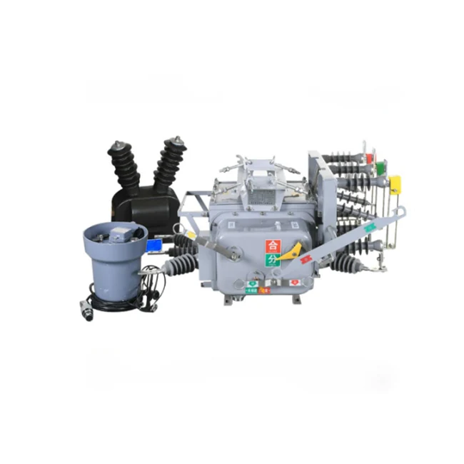
The product is specified as a user boundary vacuum circuit breaker for the demarcation point between grid operator and end user. It integrates the breaker body, CT/ZCT signals, PT supply and FDR boundary controller.
The datasheet treats the product as an integrated boundary protection set: vacuum circuit breaker main body, built-in phase CT, built-in zero-sequence residual CT, external PT and FDR intelligent boundary controller.
Outdoor vacuum interrupter, spring operating mechanism, epoxy solid insulation bushing and optional isolation disconnector form the main switching body.
Built-in phase CT and zero-sequence residual CT provide current and residual-current signals for user-side fault judgment.
The external pole-mounted PT supplies controller power and voltage sampling, so the field layout must leave room for the PT and wiring arrangement.
The controller handles protection logic, fault memory, local display, communication module and sealed aviation-plug wiring to the switch body.
The controller compares CT, zero-sequence CT and PT signals with preset thresholds. It trips for user-side ground faults, locks after user-side interphase short-circuit events, records fault data and sends status to a distribution automation system when communication is included.
Detects residual current from the zero-sequence CT and trips the boundary breaker to prevent a user-side ground fault from spreading on the main feeder.
After the substation outlet breaker trips and recloses, the boundary switch remains open to isolate the faulty customer branch.
Line voltage, phase current and zero-sequence current support overload alarms, overvoltage or undervoltage detection and post-fault maintenance checks.
The datasheet lists RS485, DTU wireless communication and compatibility with distribution automation master stations.
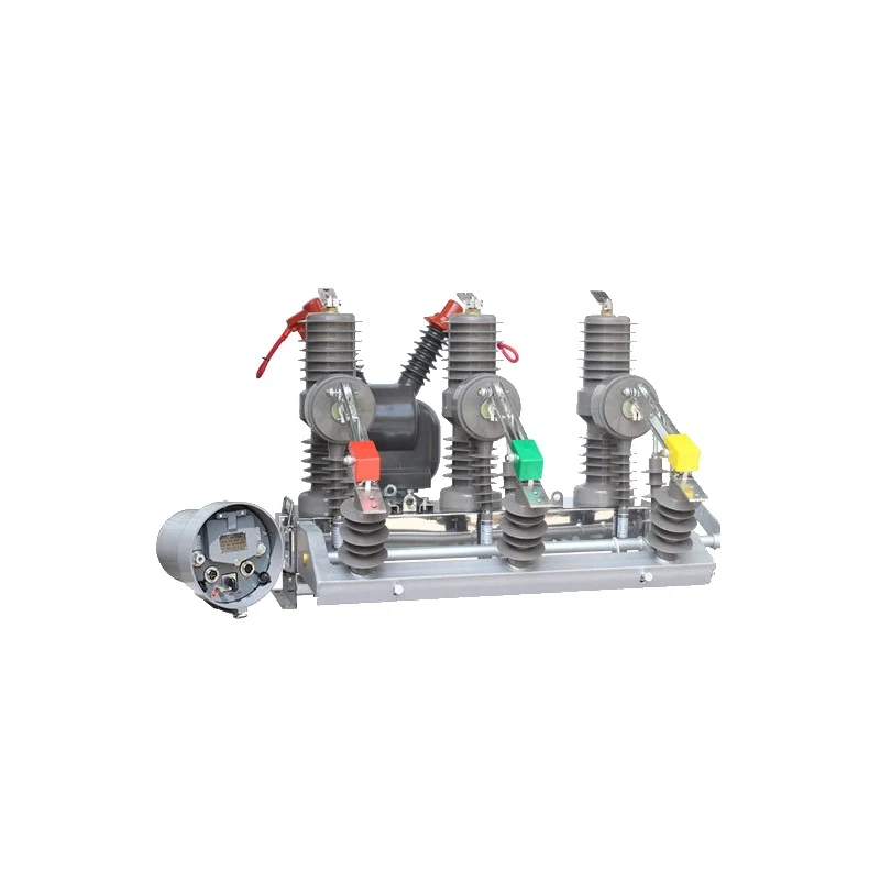
Use this product view when checking the breaker body, isolation handle, phase indicators and pole-mounted operating layout.
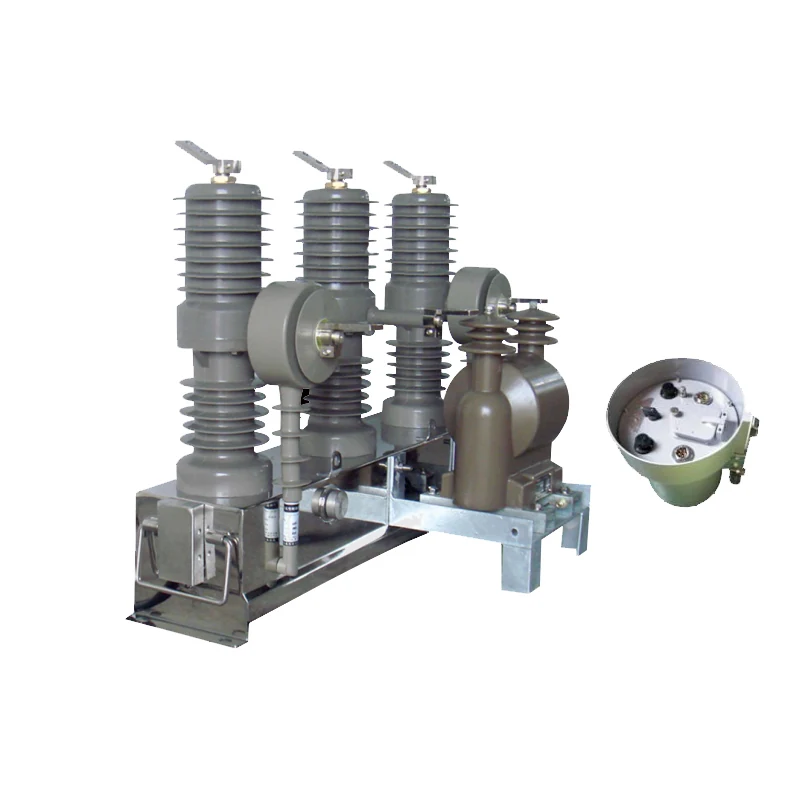
Use this view when confirming PT supply, controller interface and wiring relationship before final drawings are approved.
Install the switch at the customer demarcation point. The utility feeder remains upstream, while the boundary breaker and FDR controller isolate user-side ground faults or short-circuit faults before they interrupt other branches.
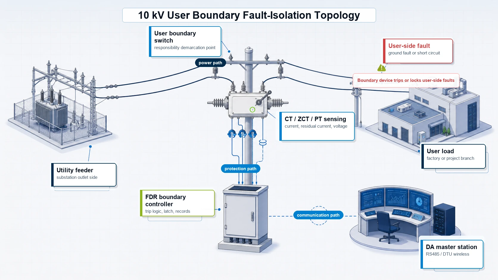
Best fit: overhead T-joint customer access points where user-side faults must be separated from the public feeder.
Fit for medium-voltage incoming lines where plant-side faults should not trip upstream network branches.
Also fits rural-grid and temporary construction supply boundaries where the utility needs clearer responsibility and faster fault location.
The page is based on the English datasheet titled User Boundary Switch (Boundary Circuit Breaker) Full English Datasheet & Specification. It defines aliases, model references, application scope, parameter table, protection principle, structure composition and quotation terminology.
The datasheet supplies ZW20-12 / ZW139A-12 model references, 12 kV parameters, FDR controller logic and application scope. The matching document can be requested during quotation review.
The review separates breaker rating, boundary-protection logic, controller communication and RFQ inputs for buyer screening.
Ask sales engineering for the English datasheet, controller setting notes, test report or installation drawing that matches the selected project.
The datasheet names these as representative outdoor vacuum boundary circuit breaker models.
The controller trips or latches the boundary switch for user-side ground faults and interphase short-circuit faults.
The external PT provides working power and voltage sampling, reducing the need for separate auxiliary field power.
Datasheet values include -40 deg C to +40 deg C, altitude <=2000 m, pollution class V, wind speed <=35 m/s and ice coating <=10 mm.
Confirm local-only control, RS485, wireless DTU or DA master-station communication before final controller configuration.
The datasheet lists ungrounded, arc-suppression-coil grounded and low-resistance grounded 10 kV grids as applicable modes.
A user boundary switch is a medium-voltage vacuum circuit breaker installed at the responsibility demarcation point between the utility feeder and the end user. It isolates user-side faults so the public feeder does not trip for every customer-side failure.
Typical sites include 10 kV overhead distribution T-joint customer taps, industrial incoming lines, rural demarcation points, temporary construction feeds and branch sectionalizing positions.
A user boundary switch focuses on customer-side fault isolation and responsibility demarcation. For broader feeder protection and reclosing, compare the Automatic Vacuum Circuit Recloser.
The datasheet describes PT voltage supply for the controller, so a separate external auxiliary power source is not the default assumption. Final PT and controller wiring still need project confirmation.
Send system voltage, rated current, short-circuit class, neutral grounding mode, boundary point role, installation photo or drawing, PT and controller requirement, communication method, quantity and destination standard.
USD 1,800-12,000 reference range depends on rated current, short-circuit class, FDR controller requirement, PT arrangement, communication method, quantity and destination standard. Confirm this is the right product type before sending an RFQ request, then send RFQ details including voltage class, neutral grounding mode, user-side fault scenario, pole installation photo, RS485 or DTU communication need and required documents. To compare adjacent Smart Grid devices, return to the Smart Grid equipment hub, review the Automatic Vacuum Circuit Recloser, compare Cutout Single-Phase Recloser or check the Smart Drop-Out Fuse for fuse-based protection points. For company background, see About XIYA POWER.