Quotation form
Send an inquiry
Start with the basics. Our team can follow up for missing drawings, standards or packing details.
Submitted details are used only for quotation, technical review and project communication.
The main product is an outdoor SF6 insulated load break switch for overhead feeder load switching, sectionalizing, loop points and transformer circuit control. Add the LBS controller only when the project needs sensing, local operation, event records or SCADA communication.
LRFW rating data defines the visible 12 / 24 / 36 kV switch-body table. Confirm the selected series before nameplate or drawing release because PGS/RPS documents describe a separate comparison series with different current, short-time, IP and standard references.
For 12 kV medium-voltage feeders requiring load current switching, line sectionalizing or transformer circuit control with a controller-ready pole switch body.
This class fits feeder sectionalizing, loop switching and transformer circuit control projects where the application voltage level is 24 kV.
For feeder voltage and insulation levels requiring the 36 kV application group. Confirm installation space and terminal dimensions before final drawing.
These shared values belong to the LRFW table, not a merged PGS/RPS table: 5000 mechanical operations, 400 rated full-load operations, IP65 protection level, SF6 gas as both arc-extinction and insulation medium, and SF6 gas yearly leak rate <=0.5%. Service conditions include altitude <=3000 m, -40 deg C to +50 deg C air temperature, maximum wind speed <=34 m/s and pollution grade III / IV. The separate RPS/PGS comparison series lists IEC 62271-103, 400 / 630 / 800 / 1250 A, 20 kA / 4 s, IP67 and suspended or horizontal mounting, so do not merge those values into this LRFW table.
The buyer selects the outdoor SF6 LBS body first. Controller cabinet, motor wiring and communication interface are added after body rating, mounting method and sensing plan are fixed.
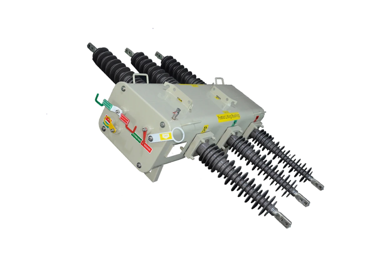
The LRFW structure sheet identifies the outdoor switch body as the high-voltage equipment: lift handle, carrying handle, rubber bushing, manual operation handle, contact position indicator, support frame, grounding device, locking device, gas pressure relief, electric mechanism, SF6 pressure gauge and filling valve.
The LBS controller supports sensing, motorized operation, alarms, records and communication after the switch body is selected. It does not make this device an automatic vacuum circuit recloser for fault-current interruption.
The controller provides phase and ground current sensing, three-phase voltage sensing, and can compute power, energy, power factor and power flow direction.
Settings can be programmed from the front panel, PC configuration software or web browser through temporary Ethernet or USB access.
The manual references RS-232, Ethernet and RS-485 ports for SCADA or interconnection to other devices.
The controller tools include event recording, data profiler, application one-line diagram, oscillography and time-current curve functions.
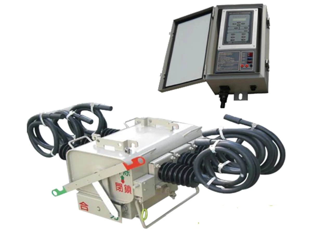
Package scope: switch body, controller cabinet, cable accessories and motorized operation.
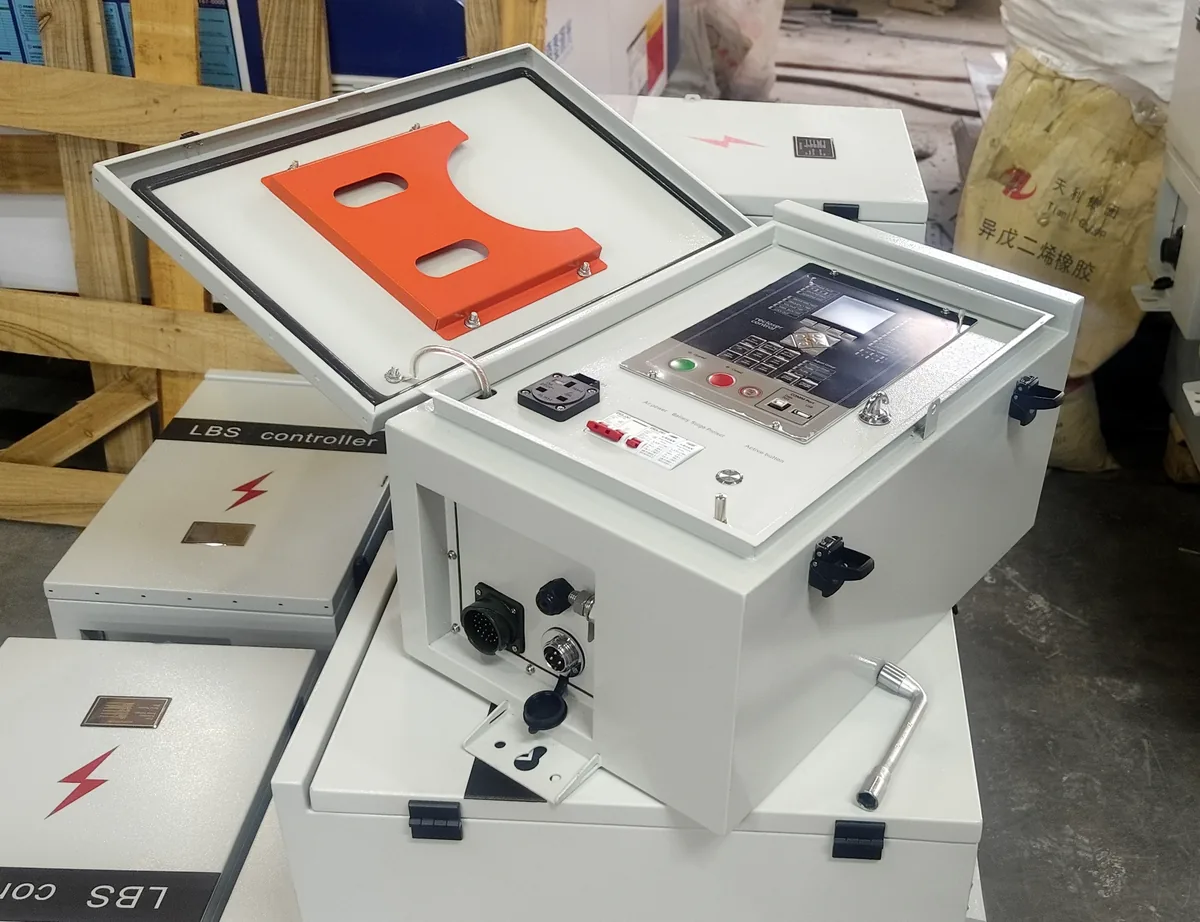
Select the cabinet after the switch rating, mounting method, sensor requirement, motor wiring and communication interface are fixed.
The topology separates the main feeder load-current path from optional sensing, command and communication paths.
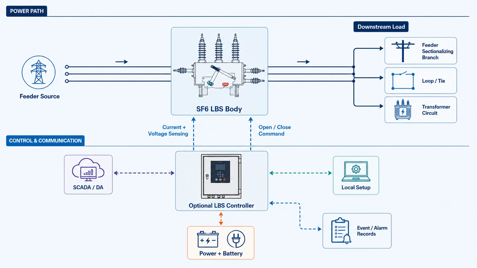
The SF6 load break switch body opens and closes load current on overhead distribution feeders, branch circuits, loop points or transformer circuits.
Add the LBS controller when the site needs sensing, event records, communication and local or remote operation.
The RFQ should state whether the buyer needs only the LRFW switch body or the switch body plus intelligent controller and wiring review.
Use installation, dimensional and wiring drawings to confirm pole mounting, terminal clearance and controller connections before production approval.
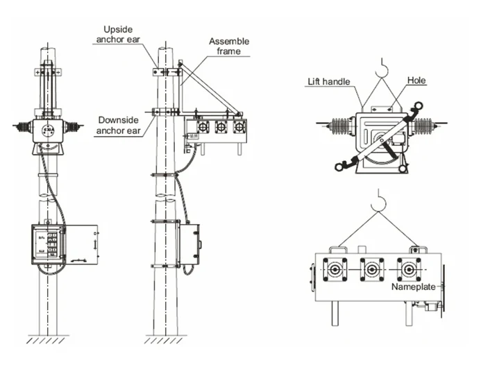
Confirm anchor ears, assembly frame, lift handle, hole, nameplate position and controller box location from the installation drawing.
Check outline dimensions, installation hole distance and terminal connection size before production drawings are approved.
When the intelligent controller is selected, review command, status, power, CT/VT or voltage sensor and communication paths from the wiring drawing.
Check anchor ears, assembly frame, lift handle, nameplate and controller box position before the final drawing is approved.
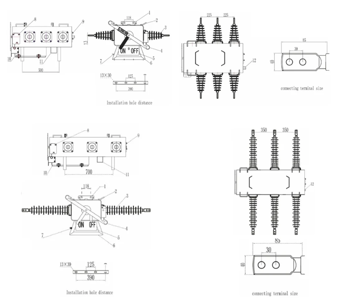
Check outline dimensions, installation hole distance and terminal connection size against the selected voltage class.
LRFW sheets, RPS/PGS comparison material, LBS controller manuals and wiring drawings support different decisions. The page keeps rating data, controller functions and engineering review separate.
These files supply the visible 12 / 24 / 36 kV, 400 / 630 A table, service conditions, single-pole installation data and structure list.
This material lists IEC 62271-103, 6-40.5 kV, 400 / 630 / 800 / 1250 A, 20 kA / 4 s, IP67 and suspended or horizontal mounting. Treat it as a separate series check.
These files support phase and ground current sensing, voltage sensing, SCADA ports, AC input, control circuit, power circuit and terminal definitions.
The RPS/PGS catalog references IEC 62271-103. One supplied LRFW sheet references IEC 62271-200. Confirm the selected model and buyer standard before making a compliance statement.
The sheet identifies lift handle, carrying handle, rubber bushing, manual operation handle, position indicator, support frame, grounding device, locking device, pressure relief device, electric mechanism, pressure gauge and filling valve.
The installation drawing shows upside and downside anchor ears, assembly frame, controller box position, lift handle, hole and nameplate position.
Confirm altitude <=3000 m, -40 deg C to +50 deg C, humidity, wind speed <=34 m/s, icing <10 mm, snow <35 mm and pollution grade III / IV.
The LRFW table lists SF6 gas as arc-extinction and insulation medium, with SF6 gas yearly leak rate <=0.5%. RPS/PGS comparison data lists a separate <=1% yearly gas leakage reference.
Request the selected series, final nameplate, dimensional drawing, single-pole installation confirmation, wiring diagram, controller settings basis and inspection record.
It is an outdoor SF6 insulated load break switch installed on overhead distribution feeders for load current switching, line sectionalizing, loop points and transformer circuit control. The LBS controller is an optional automation package for sensing, alarms, local operation and SCADA communication.
No. The SF6 LBS is for load current switching and sectionalizing. If the project needs fault-current interruption with automatic reclosing protection, compare the Automatic Vacuum Circuit Recloser.
Confirm the selected switch series first, then voltage class, rated current, short-time withstand or breaking requirement, terminal or cable outlet style, operating method, service environment and mounting condition.
The RPS/PGS catalog references IEC 62271-103. One supplied LRFW sheet references IEC 62271-200. Treat these as supplier-document notes until the selected model and purchaser standard are confirmed.
The controller manual references front-panel operation, PC software and web programming, Ethernet and USB access, plus RS-232, Ethernet and RS-485 ports for SCADA or device interconnection.
Send system voltage, rated current, feeder role, short-circuit level, terminal or cable outlet style, mounting method, manual or electric operation, CT/VT sensing, controller or SCADA needs, destination standard, quantity and site drawings or photos.
USD 1,200-9,500 reference range depends on voltage class, rated current, controller cabinet, sensing package, motor wiring, mounting details and quantity. Confirm this is the right adjacent Smart Grid equipment type before sending an RFQ request, then send RFQ details including selected series, feeder role, loop or sectionalizing requirement, terminal or cable outlet style, mounting drawing, service environment, CT/VT sensing, SCADA interface and destination standard. To compare adjacent equipment, return to the Smart Grid equipment hub, review User Boundary Switch or compare the Automatic Vacuum Circuit Recloser. For company background, see About XIYA POWER.