Quotation form
Send an inquiry
Start with the basics. Our team can follow up for missing drawings, standards or packing details.
Submitted details are used only for quotation, technical review and project communication.
Start with the basics. Our team can follow up for missing drawings, standards or packing details.
Submitted details are used only for quotation, technical review and project communication.
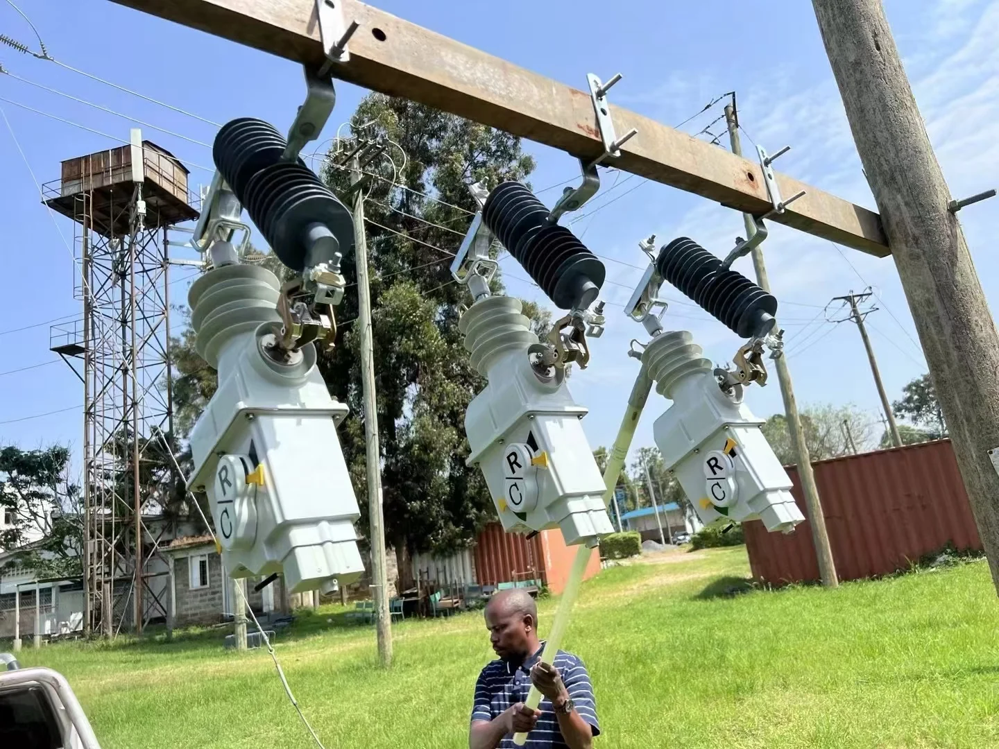
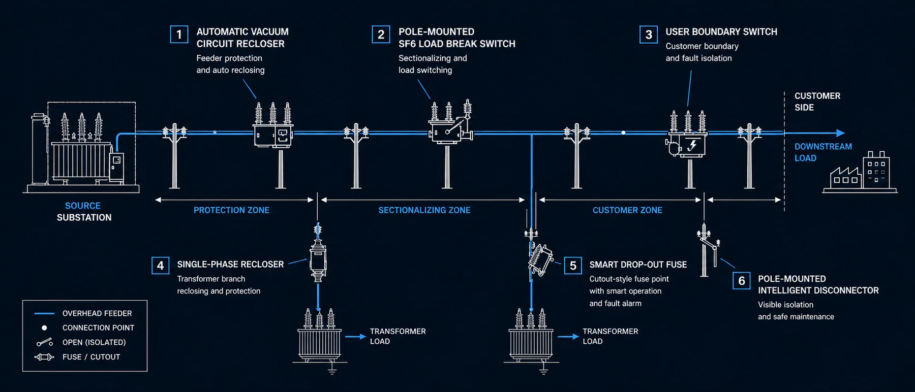
Select the right pole-mounted device family for feeder reclosing, transformer branch protection, customer boundary isolation, load switching, no-load isolation and smart fuse operation.
Match feeder protection, transformer branch protection, customer boundary isolation, no-load isolation, load switching and smart fuse operation to the correct product page.
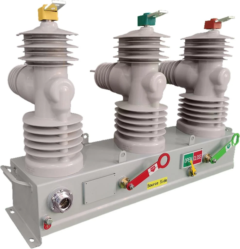
15-38 kV outdoor vacuum recloser for feeder protection, fault isolation, automatic reclosing and controller communication.
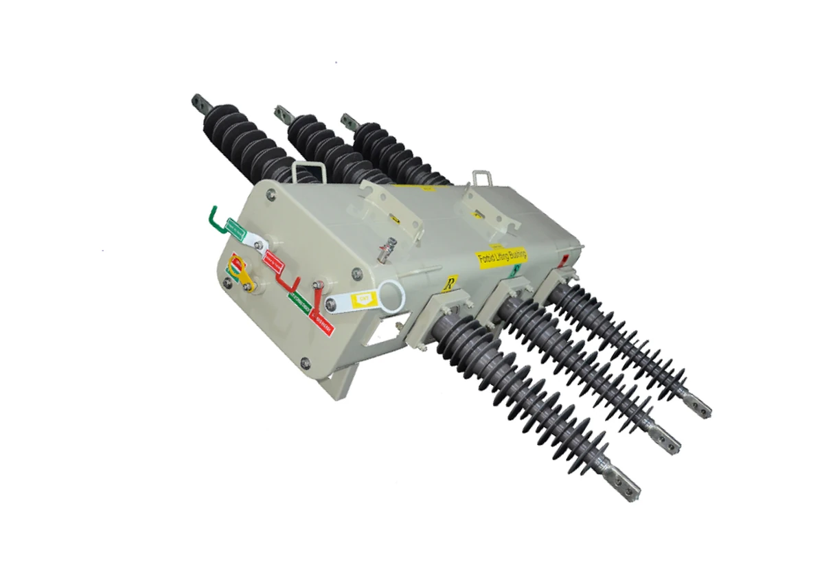
SF6 insulated load break switch for overhead feeder load switching, sectionalizing, loop points and transformer circuit control.
12 kV boundary breaker for 10 kV customer demarcation points, user-side fault isolation and FDR controller-based distribution automation.
Cutout-mounted recloser for transformer branches, rural feeders and boundary points where transient faults should clear without repeated fuse replacement.
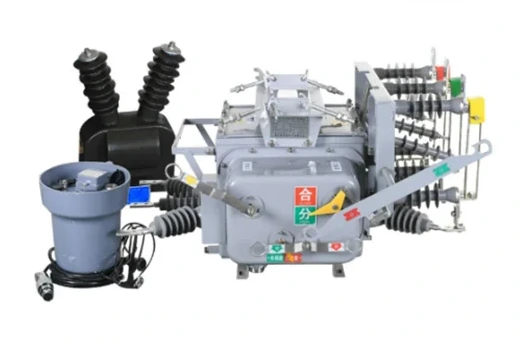
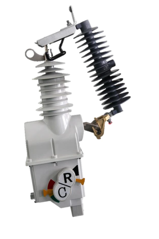
12 kV smart fuse equipment for outdoor transformer and branch-line fuse points that need motorized operation, remote control or fault alarm support.
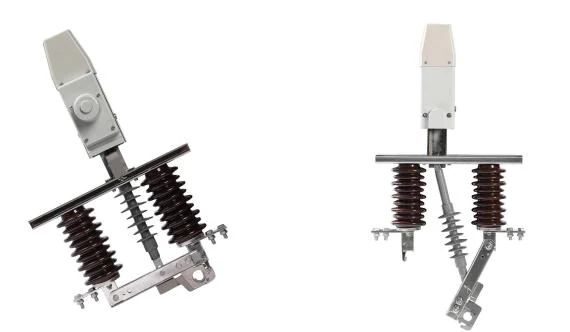
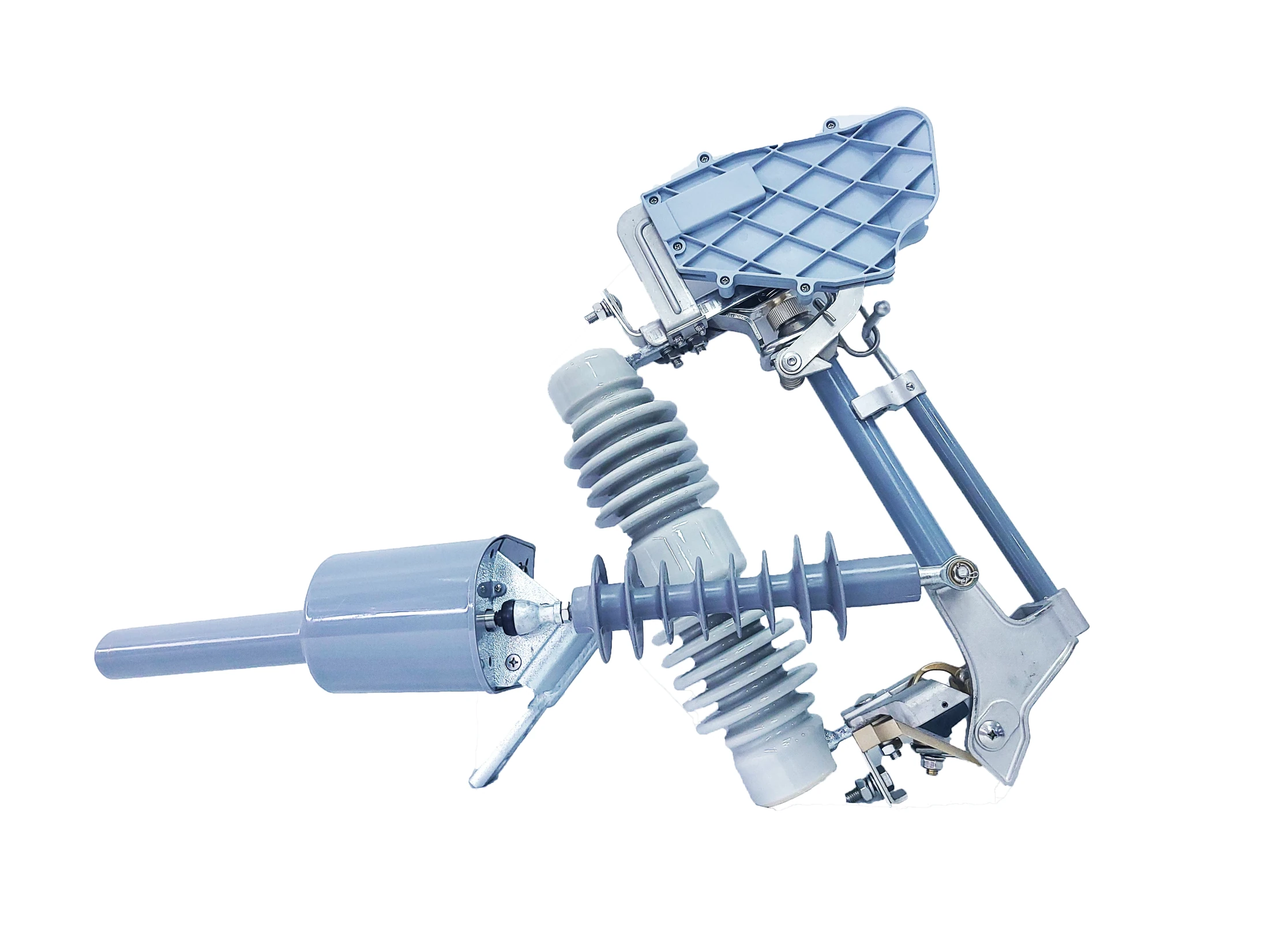
12-24 kV pole-mounted disconnector for visible no-load isolation, remote-assisted open-close operation and ICC terminal control.
Locate the duty point first: feeder protection, load switching, customer boundary, transformer branch or visible isolation.
For feeder fault interruption, reclosing and controller communication.
For switching load current at sectionalizing, loop or transformer points.
For 10 kV demarcation points and user-side fault isolation.
For cutout-style branch points that need reclosing, smart operation or alarms.
Start with the primary device, then confirm controller, sensing, auxiliary supply and communication inputs.
One primary device can require several control inputs before wiring drawings and controller settings are finalized.
Switching or protection duty defines the controller family.
Logic settings, local operation, event records and remote command interface.
Communication protocol, events and dispatch integration.
Auxiliary power and voltage sampling.
Phase current for protection and measurement.
Zero-sequence input for grounding fault logic.


Match ACR, LBS, ICC or FDR functions to the selected device family.
Confirm auxiliary power method and voltage sampling requirements.
Confirm phase-current inputs for protection and measurement logic.
Use zero-sequence input where grounding fault logic is required.
Confirm protocol, event records and remote operation before shipment.
Keep model selection tied to the files engineering and procurement can actually review.
Rating class, product family scope and application notes.
Installation method, operating limits and accessory context.
Dimensions, pole interface, wiring or terminal arrangement.
Routine test reference or inspection evidence where available.
For controller-based projects, add controller notes, PT / CT / ZCT input details and SCADA protocol requirements before shipment configuration.
ACR, SF6 LBS, boundary switch, single-phase recloser, smart fuse and disconnector pages do not use the same review package.
Voltage class, current, breaking or switching duty, pole arrangement and transformer branch position should be confirmed against the actual line role.
Controller family, auxiliary supply, PT / CT / ZCT inputs, motor drive and protocol requirements should be checked before drawing approval.
Use lightweight RFQ inputs for budget quoting, then request manuals, dimensional drawings and test references for technical approval.
Updated June 26, 2026. XIYA POWER uses this hub to route overhead distribution automation inquiries to the right product family before model-level quotation.
Catalogs, manuals, drawings and routine test references are handled after the device family is clear.
Controller, PT / CT / ZCT, motor drive and protocol inputs are reviewed before wiring details are locked.
Quantity, destination, utility standard and packing needs are collected with the electrical parameters.
Feeder reclosers, SF6 LBS, boundary switches, single-phase reclosers, smart fuses and disconnectors remain separate selection paths.
For Smart Grid equipment, a useful inquiry should define line role, electrical class, control package, communication requirement, quantity, destination and any utility standard or drawing reference.
Feeder reclosing, transformer branch, customer boundary, isolation point or load switching.
Voltage, current, breaking or switching duty, insulation level and frequency.
Controller, terminal, motor drive, sensing, power supply, protocol and remote operation.
Photos, single-line diagram, pole arrangement, utility standard, quantity and destination.
Use an automatic vacuum circuit recloser when the overhead feeder needs fault interruption, protection settings, automatic reclosing and controller communication. Use a single-phase recloser only for cutout-mounted branch or transformer points.
Use a user boundary switch at the utility-to-customer demarcation point when the project needs user-side fault isolation, responsibility separation, CT / ZCT fault signals, PT supply and an FDR boundary controller.
Use a single-phase recloser when reclosing logic and protection settings are required at a cutout-mounted point. Use a smart drop-out fuse when the site should keep a fuse body but add motorized operation, remote control accessories or fault alarm support.
Use an SF6 load break switch for load current switching, sectionalizing, loop points and transformer circuit control. Use an intelligent disconnector for visible no-load isolation and remote-assisted open-close operation.
Confirm controller family, auxiliary supply, PT / CT / ZCT inputs, motor drive, communication protocol, event records and remote operation requirements before drawings and controller settings are locked.
Send application point, voltage class, rated current, frequency, breaking or switching duty, phase count, controller requirement, communication protocol, installation photos or drawings, quantity, destination and any utility standard.