Quotation form
Send an inquiry
Start with the basics. Our team can follow up for missing drawings, standards or packing details.
Submitted details are used only for quotation, technical review and project communication.
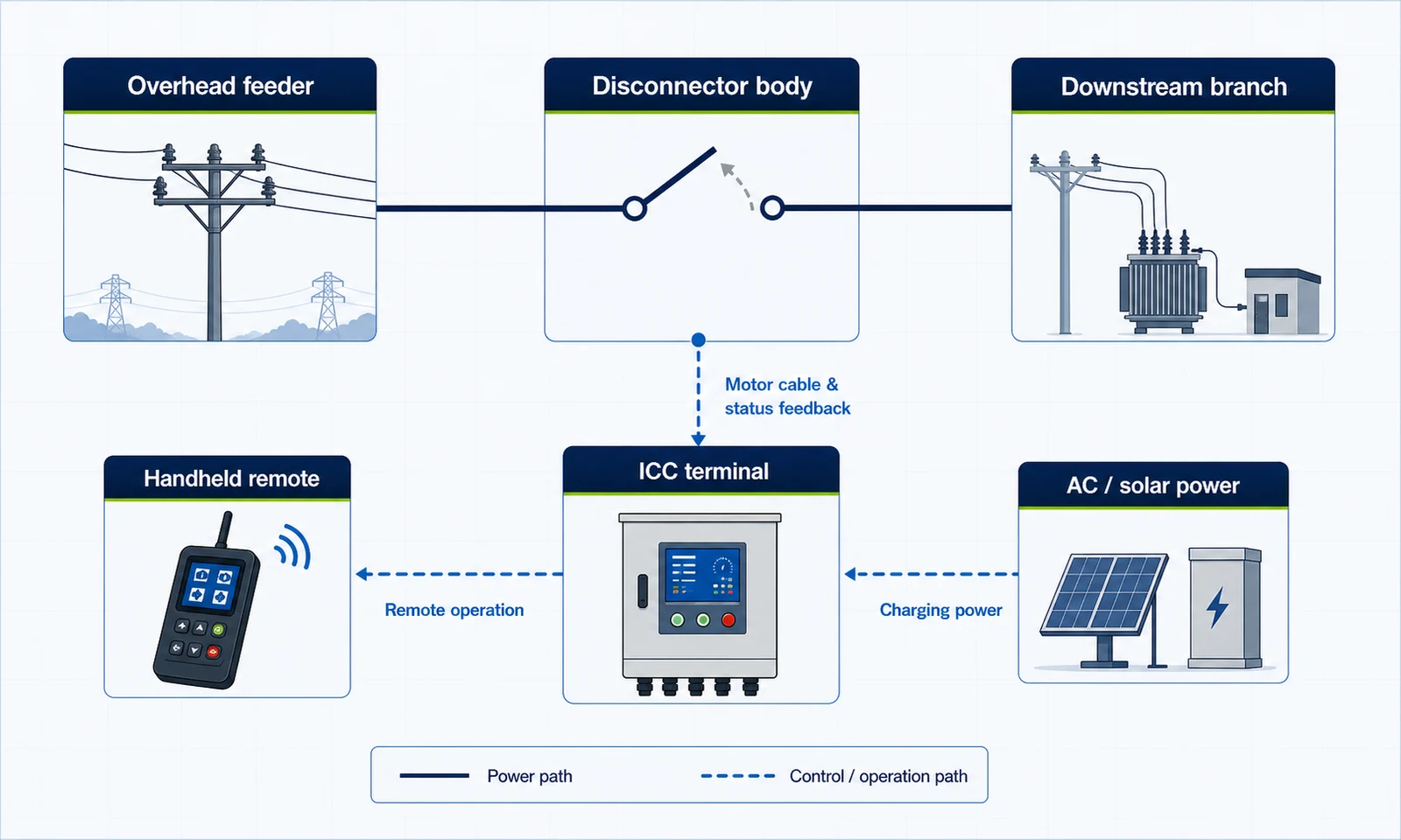
12-24 kV pole-mounted intelligent disconnector for outdoor no-load isolation, remote-assisted opening and closing, and ICC terminal operation packages. The switch body creates the visible isolation point; the controller, motor cable and handheld remote define how crews operate it.
The manuals cover two rating layers. Use the 12 kV DGDW1 installation manual for the ICC installation set, or the 24 kV GWT24 manual for the outdoor isolating switch basis. Keep those tables separate until the selected model is fixed.

Select this layer when the RFQ follows the DGDW1 installation manual and needs the switch body, ICC terminal, handheld controller, motor cable and charging parts as one site package.

Select this basis when the project is based on the GWT24-24 outdoor AC intelligent isolating switch manual. The manual frames the device as a single-pole outdoor disconnector for no-load operation.
First choose the switch body and rating layer. Then select ICC terminal, handheld controller, receiver, motor cable, charging method, optional solar panel and pole mounting layout. This prevents the control package from being quoted before the isolating switch duty is clear.
The disconnector body creates the visible isolation point. The electric transmission mechanism, insulating push-pull rod and actuator move the switch blade, while the ICC terminal controls the operation package.
Base or channel steel, insulator support, incoming and outgoing terminals and conductive copper bar form the outdoor visible isolation point.
The electric transmission mechanism drives the opening and closing actuator through an insulating push-pull rod rather than changing the switch into a breaker.
The monitoring terminal mounts on the pole with a user-prepared clamp. The built-in battery should be charged before installation.
The body mounts near the transformer crossarm. Keep high-voltage conductors more than 12 cm away from the motor cover, cable and terminal.
The disconnector is for isolation and no-load switching. The control package decides how crews search or connect to the device, open or close phases, power the terminal and confirm status.
The handheld remote uses search or connect mode, device ID and password logic before the operator sends open or close commands.
The manual interface separates A/B/C operation status. The operation interval between phases is 5 seconds and the open or close reaction time is 2 seconds.
The ICC terminal can use AC220V charging cable and optional solar charging. Confirm battery condition and charging method before installation.
Control board references include main power switch, remote or local indication, charging and link indicators, stroke feedback, RS485 and A/B/C motor control.

This manual view helps check the terminal, control system and cable relationship before shipment.

This part applies when field crews need remote-assisted open or close operation after the switch body and terminal package are fixed.
The topology separates the electrical path from the control and operation paths. It is a principle diagram for selecting the device role, not a field wiring proof.
Choose the switch body where the project needs a visible isolation point on an outdoor feeder, transformer branch or crossarm-mounted disconnector position.
Add the motorized package when crews need remote-assisted operation instead of repeated manual G-stick or hook-stick work.
Add the ICC package when the site needs terminal power, charging, status feedback and defined A/B/C motor control wiring.
The product files include a DGDW1 12 kV installation manual and a GWT24-24 English manual. This page keeps those layers separate so buyers can select the model, rating and operating package without mixing data.
Choose this basis when the RFQ follows the DGDW1 installation and packing list.
Choose this basis when the buyer is selecting the GWT24 outdoor isolating switch basis.
Controlled manual pages, revision status and inspection records can be confirmed with the quotation packet. For company background, see About XIYA POWER.
The installation manual names 12 kV, 630 A, 50 Hz, withstand values, 25 kA / 3 s short-time current and 3000 mechanical operations.
The English manual names 24 kV, 630 A, 16.20 kA / 4 s short-time withstand current, 40.50 kA peak withstand current and 125 kV BIL.
The DGDW1 packing list includes the body assembly, ICC monitoring terminal, handheld controller, motor cable assembly, charging cable and optional solar panel.
User-prepared clamps may be needed for the signal receiver and solar panel. Pole photos help confirm the terminal location and cable routing.
The order review should confirm the selected body rating, ICC terminal, handheld controller, charging method, motor cable and open or close operation package together.
The GWT24 manual states operation under no-load conditions and says the line load should be switched off before disconnecting.
Include crossarm position, transformer or downstream equipment role, phase layout, charging method and required remote operation package.

This cabinet photo belongs only to the controller and power-package layer. It is not the primary switch body.
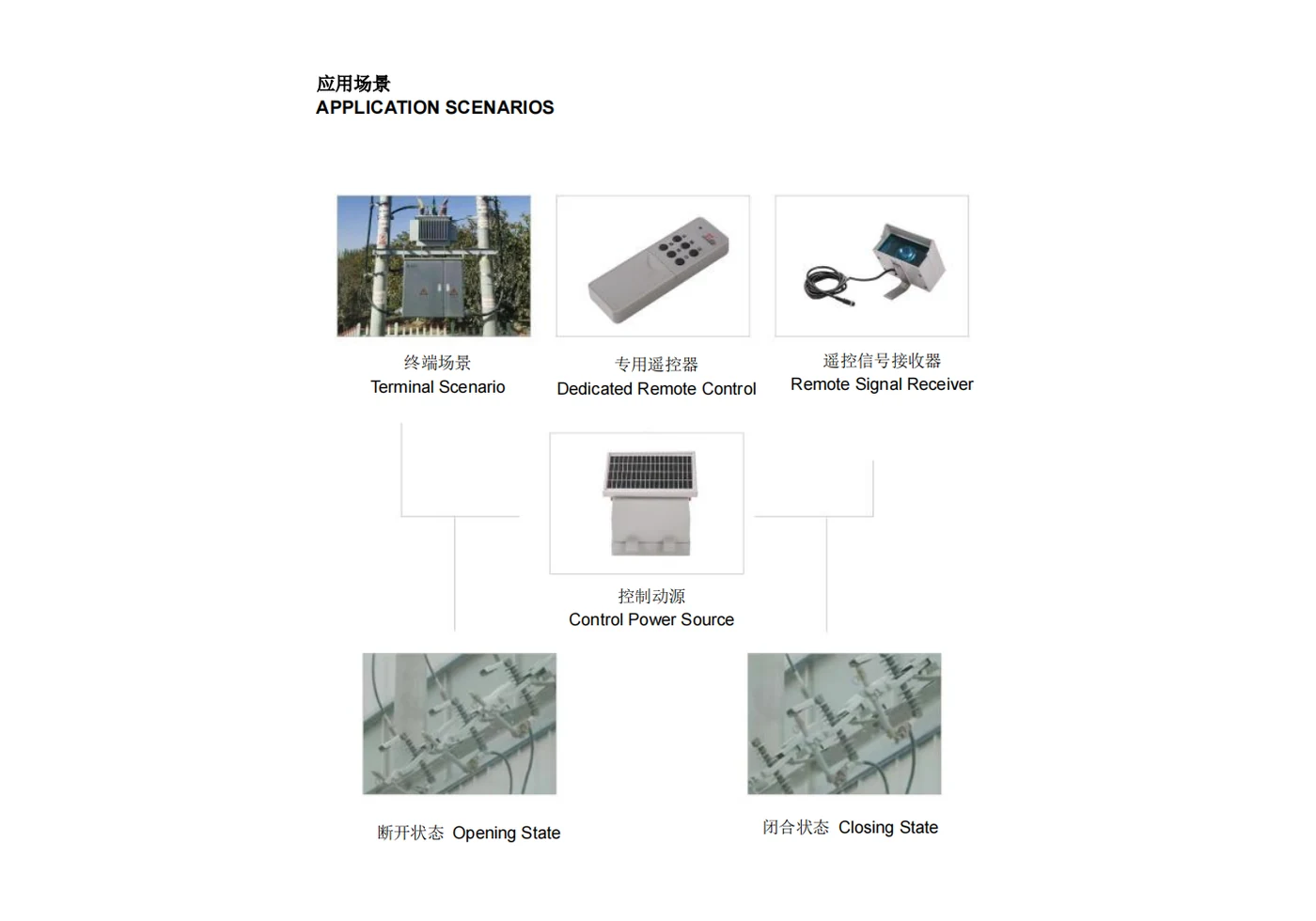
These manual views help discuss terminal, receiver, power source and open or close status before final accessory selection.
It is an outdoor isolating switch with a motorized operating layer and ICC or handheld control package. The switch body creates the visible isolation point. It is not a circuit breaker or automatic recloser.
No. The GWT24 manual describes opening and closing under no-load conditions and says line load should be switched off before disconnecting the switch. If the project needs load switching, compare the Pole-Mounted SF6 Load Break Switch (IACT). If it needs fault interruption and reclosing, compare the Automatic Vacuum Circuit Recloser.
The disconnector is selected for visible isolation and remote-assisted switching of an isolation point. A Smart Drop-Out Fuse keeps fuse-based transformer or branch protection as the main function.
Choose the 12 kV DGDW1 installation manual or the 24 kV GWT24 manual according to the selected model. Do not merge the two rating sets before the model basis is confirmed.
Confirm the ICC terminal, handheld controller or remote transmitter, receiver, motor cable, AC220V or solar charging, battery check, A/B/C plugs and pole clamps.
Send voltage class, rated current, selected model, no-load isolation role, pole or crossarm photo, phase layout, ICC terminal package, charging method, remote requirement, safety clearance, quantity and destination standard.
Indicative FOB equipment range for early budgeting. Final quote depends on rating class, controller package, quantity, destination and utility standard.
Use the line position to confirm whether this page is the right product type.
Pole arrangement, ICC terminal, auxiliary supply, handheld controller and accessory list.
Send drawings, photos, electrical ratings and export requirements through the RFQ form.
Start with voltage class, rated current, selected DGDW1 or GWT24 basis, no-load isolation role, crossarm or pole photos, ICC terminal, handheld controller, motor cable, AC or solar charging, A/B/C wiring, 12 cm safety distance, quantity and destination standard. To compare adjacent Smart Grid products, return to the Smart Grid equipment hub, review the Smart Drop-Out Fuse, compare Pole-Mounted SF6 Load Break Switch (IACT) or check Automatic Vacuum Circuit Recloser. For manufacturer background, see About XIYA POWER.