Quotation form
Send an inquiry
Start with the basics. Our team can follow up for missing drawings, standards or packing details.
Submitted details are used only for quotation, technical review and project communication.


Compare disconnect switches, load break switches, circuit breakers, surge arresters, composite insulators and drop-out fuses by application point, electrical duty and installation requirements.
Choose by primary duty, then confirm voltage class, application point, mounting method and required accessories.
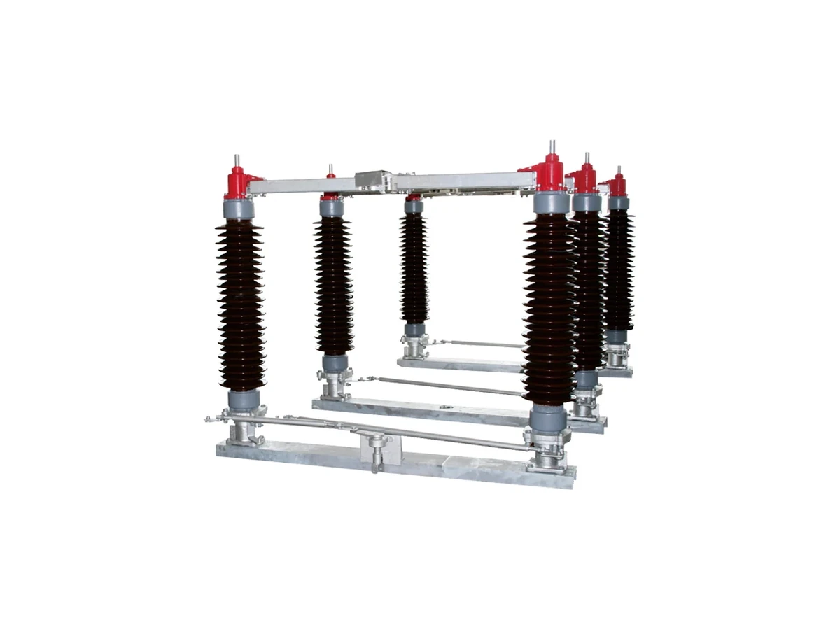
Visible no-load isolation for overhead lines, substations and switchgear using outdoor or indoor disconnector types.
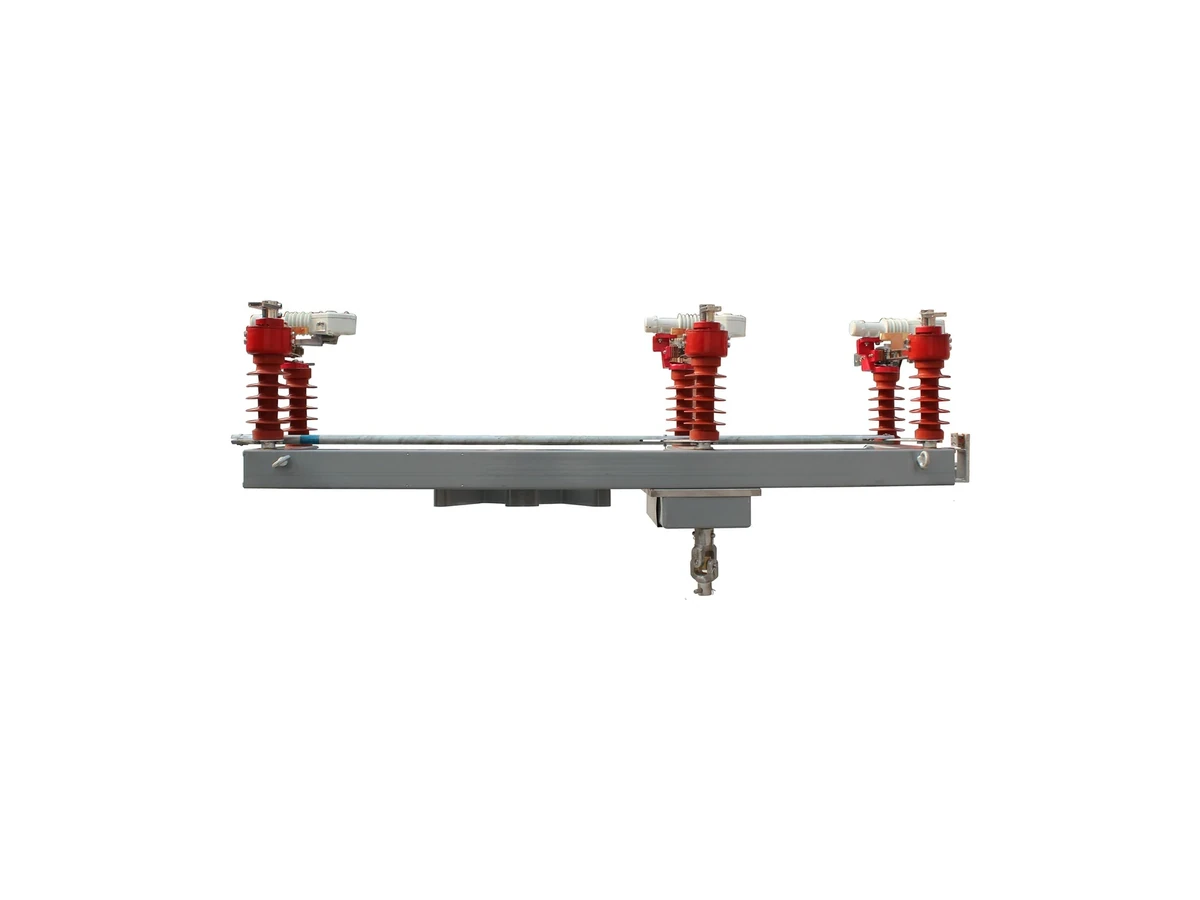
Rated load-current switching and feeder sectionalizing for indoor switchgear and outdoor distribution points.
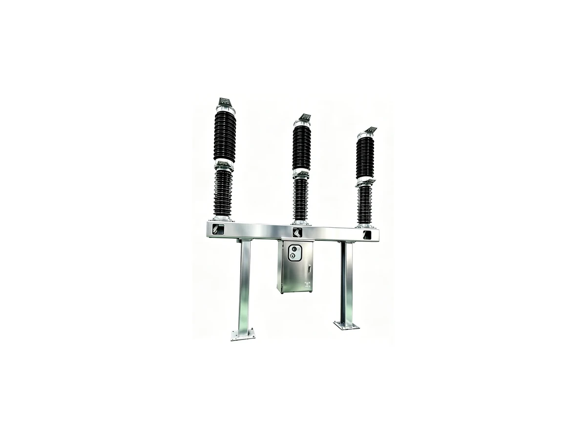
Fault-current interruption and feeder protection for indoor panels, substations and pole-mounted applications.
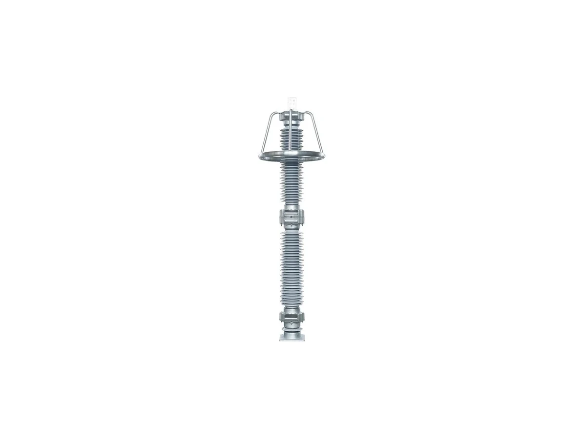
Lightning and switching overvoltage protection for distribution lines, transformers, substations and connected equipment.
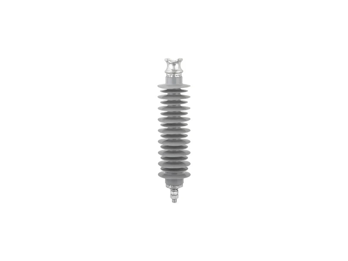
Electrical insulation and mechanical support for suspension, tension, line-post, crossarm and equipment interfaces.
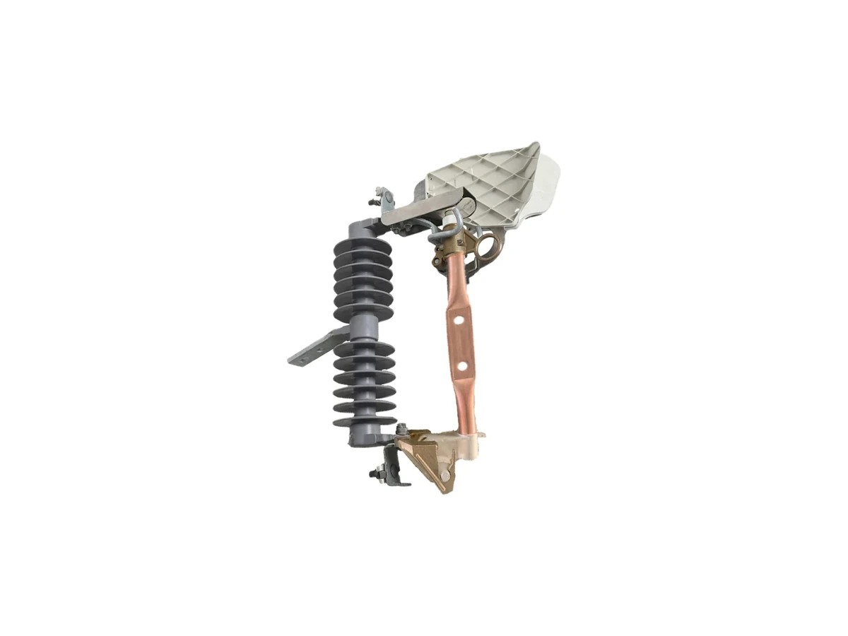
Overcurrent protection for transformer branches, lateral lines and overhead feeder taps with project-specific fuse links.
Use the main feeder, protected branch and equipment-support layers to locate the required duty. The categories are selected by application, not as a prescribed series connection.
Feeder bays, substations, pole-mounted protection points and indoor panels.
View circuit breakers Visible isolationDisconnect SwitchesNo-load isolation before maintenance at line, substation and switchgear positions.
View disconnect switches Load switchingLoad Break SwitchesRated load switching and sectionalizing at indoor or outdoor feeder points.
View load break switches Overvoltage path to earthSurge ArrestersLine terminals, transformers, substations and connected equipment.
View surge arresters Transformer and lateral branchDrop Out FusesOvercurrent protection on transformer branches, lateral lines and overhead feeder taps.
View drop out fuses Insulation and mechanical supportComposite InsulatorsConductor, crossarm and equipment support across line and substation structures.
View composite insulatorsStart with the primary system duty, then confirm the category-specific ratings, installation details and accessory package on the relevant technical page.
Select a category to follow its operating input, equipment action and electrical result. The final band identifies the structure to confirm on the selected series drawing.
After upstream equipment removes load and fault current, the operating linkage opens the blade or contact set to establish a visible isolation point.
Blade or moving contact, fixed contact, insulators, operating linkage and interlock interface.
An operating drive moves the contacts while the selected arc-control or interruption medium manages rated load-current switching.
Main contacts, arc-control or interruption medium, operating drive and mounting interface.
A protection or control command releases the mechanism so the contacts separate and the interrupter clears the fault current.
Trip release, operating mechanism, contacts and interruption chamber.
The MOV column becomes conductive during a transient, diverts surge current to earth and returns to high resistance afterward.
MOV blocks, housing, line and earth terminals, earth lead and optional disconnector or counter.
The core rod carries mechanical load while the polymer housing and sheds maintain the external insulation path.
Core rod, polymer housing and sheds, end fittings and interface hardware.
Overcurrent melts the fuse link; the arc is extinguished and the released fuse tube drops to a visible open position.
Fuse link, fuse tube, upper and lower contacts, hinge and mounting bracket.
A shared system voltage does not make rating rows interchangeable. Use the selected category’s own series data, installation type and applicable standard.
Interruption, insulation, mechanical and accessory ratings remain attached to the equipment type and series that defines them.
Each category separates its rating basis from values that must remain within another equipment type, series or installation.
Rated voltage, normal current, insulation level, short-time withstand and isolating distance for the selected indoor or outdoor series.
Do not transfer load-breaking or fault-interruption data from load break switches or circuit breakers.
Operating mechanism, pole or panel arrangement, earthing function and the selected series drawing.
Rated voltage, normal current, frequency, load-breaking current, short-circuit making capacity and insulation level for the selected interrupter design.
Do not substitute circuit-breaker fault interruption data or disconnect-switch no-load duty.
Indoor or outdoor construction, interruption medium, fuse or controller package and operation method.
Rated voltage and current, short-circuit breaking and making current, short-time withstand, insulation level and operating sequence.
Do not copy load-break switching values, controller data or accessory ratings from another breaker series.
Relay or controller, control voltage, CT interface, reclosing need and installation type.
Rated voltage, MCOV, nominal discharge current, residual voltage, energy capability, creepage distance and housing type.
Do not select MCOV or residual voltage from system nominal voltage alone, or use monitor and counter ratings for the arrester body.
Grounding arrangement, altitude, pollution level, housing type and disconnector or counter need.
Voltage class, creepage distance, specified mechanical or cantilever load, interface dimensions and housing profile.
Do not mix suspension, tension, line-post, crossarm, bushing or accessory values between product types.
End fittings, load direction, conductor or equipment interface, pollution level and outline dimensions.
Rated voltage, continuous current, rated breaking current, insulation level and fuse-link characteristic for the selected cutout.
Do not use fuse-holder current alone to select the fuse-link rating or interrupting duty.
Fuse-link type, transformer or lateral protection coordination, mounting angle, bracket and environmental conditions.
Start with the selected equipment category and series. Confirm its rating data, installation interfaces and required project documents before model approval.
Match voltage class, normal current, insulation level and the duty-specific rating to one identified equipment series and applicable standard.
Category, series, standard and revision are identified on the same data set.
Check overall dimensions, mounting holes, terminal orientation, operating mechanism interface and required electrical or mechanical clearances.
Request an outline or mounting drawing whenever fixed dimensions affect the installation.
Confirm applicable standards, test or inspection records, packing details and any destination documentation required for approval.
Document titles, model references and applicable revisions agree with the selected equipment.
Product photos can help identify construction. They do not replace series rating data, and an accessory drawing does not define main-equipment performance.
Choose the equipment category first, then provide the conditions that affect ratings, construction, interfaces and document scope.
Equipment category, application position and required duty: isolation, load switching, fault interruption, surge protection, insulation support or fuse protection.
System voltage, frequency, rated current, short-circuit or switching duty, insulation level and the applicable utility or IEC standard.
Indoor or outdoor use, pole, panel, cabinet or structure mounting, altitude, pollution level, ambient temperature and operating method.
Outline or mounting drawing need, accessories, control voltage where applicable, quantity, destination country, inspection and packing requirements.
It covers outdoor disconnect switches, outdoor air break switches, fuse disconnect switches, earthing switches, bypass disconnectors and indoor disconnect switches used for line isolation, sectionalizing, grounding and maintenance switching decisions.
Use an outdoor disconnect switch when the main requirement is visible no-load isolation. Use an outdoor air break switch when the line point also needs air break switching or sectionalizing within the selected rating and operating method.
Choose a fuse disconnect switch when fuse protection and visible isolation belong at the same transformer branch, feeder tap or outdoor line protection point. Send fuse carrier or fuse link requirements with the voltage and current class.
Review earthing switches when the operating sequence needs a dedicated grounding point. Review bypass disconnectors when a recloser, breaker or switching device needs a service bypass path for maintenance.
Send voltage class, rated current, line position, isolation or switching duty, operating mechanism, mounting photos or drawings, quantity, destination country and any utility standard requirement.
No. The hub should narrow the product family first. Model selection comes after voltage, duty, installation drawings and document requirements are known.