Earthing switch product types

Earthing Switches for Maintenance Grounding and Interlock Sequence

Earthing switches ground an isolated circuit before maintenance work. Compare JN15, JN17 and GN22 earthing switch product types up to 33 kV by grounding sequence, short-time withstand duty, operating shaft and mounting interface.

Product types

Earthing Switch Types

Start with the maintenance grounding point. JN15, JN17 and GN22 can be reviewed up to 33 kV, while short-time duty, phase distance and mounting release still need the model-specific order file.
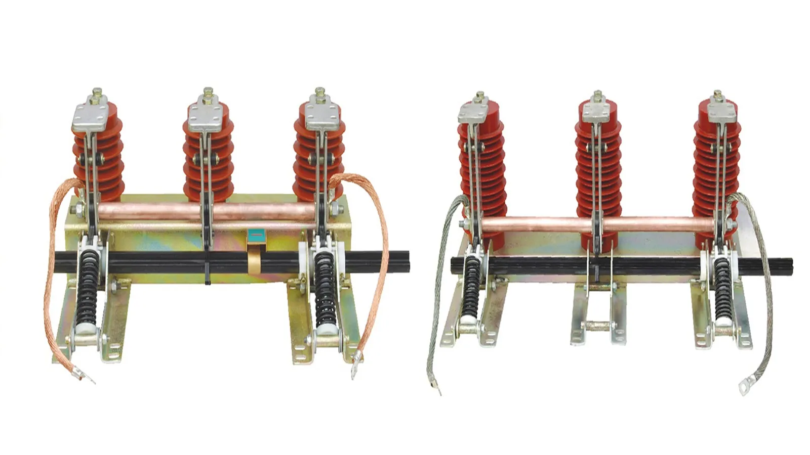
JN15 combined earth switch with three phase grounding shaft and insulators
ES 01up to 33 kV

JN15-12/31.5 Combined Earth Switch

Indoor earthing switch type for switchgear grounding positions where short-time withstand and interlock sequence matter.
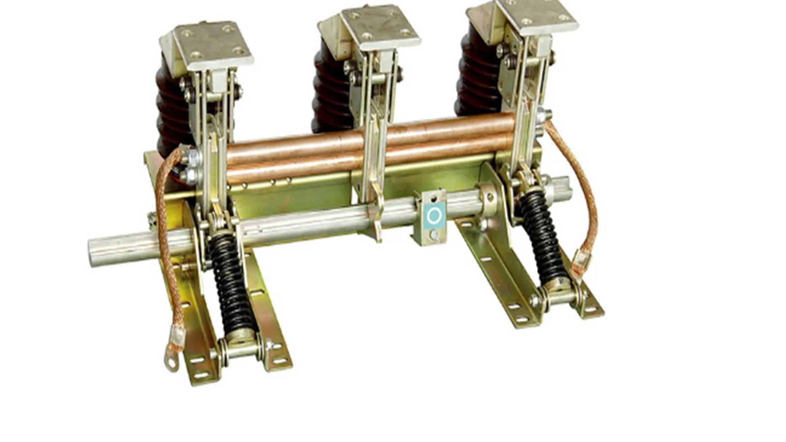
JN17 indoor high-voltage grounding switch with copper earth bar and operating shaft
ES 02up to 33 kV

JN17(15)-12/40 Indoor Grounding Switch

Indoor high-voltage grounding switch for cabinet grounding protection after the isolation position is known.
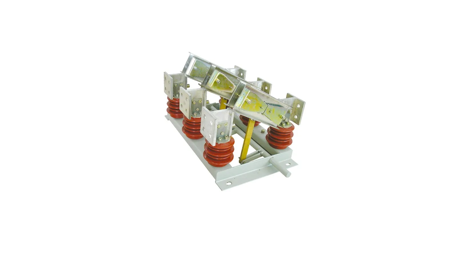
GN22 three-column earthing switch product on clean white background
ES 03up to 33 kV

GN22 Three-Column Earthing Switch

GN22 three-column earthing switch configuration for grounding blade, insulator and base-frame structure checks.

Reference basisEarthing switch selector with three confirmed product types.

JN15, JN17 and GN22 are the selected product types for this earthing switch selector. Keep GN10 and unrelated disconnect references out of this selector.

JN15-12/31.5Up to 33 kV project capability with listed short-time duty and phase-distance rows.
JN17(15)-12/40Up to 33 kV project capability with 40 kA / 4 s listed duty and opening layout rows.
GN22Three-column earthing switch configuration. Confirm current, short-time duty and mounting drawing by order file.
GN10 boundaryAdjacent indoor disconnect reference only. Do not mix it into the earthing switch selector.
Technical parameters

JN15-12/31.5 Combined Earth Switch Source Data

Catalog-based data from the JN15 combined earth switch pages in the supplied earthing switch folder.

Catalog referenceJN15-12/31.5 Series Combined Earth Switch catalog spread

The JN15 source pages describe an indoor high-voltage earthing switch for switch cabinet grounding operation.

The supplied table lists a 12 kV source row with 40 kA short-time withstand current, 4 s duration and 100 kA peak values. XIYA can review JN15 project voltage requirements up to 33 kV after the order model and cabinet drawing are confirmed.

Project voltage capability
Up to 33 kV after order confirmation
Catalog voltage row
12 kV source row
Rated short-time withstand current
40 kA
Rated short-circuit duration
4 s
Rated peak withstand current
100 kA
PF withstand voltage
42 kV
Lightning impulse withstand voltage
75 kV
Mechanical life
2000 times

JN15 Electrical Data

ItemCatalog value
Project voltage capabilityUp to 33 kV after order confirmation
Catalog voltage row12 kV
Rated short-time withstand current40 kA
Rated short-circuit duration4 s
Rated short-circuit current100 kA
Rated peak withstand current100 kA
Rated short-time power-frequency withstand voltage42 kV
Rated lightning impulse withstand voltage75 kV
Mechanical life2000 times

JN15 Selection Inputs

FieldWhat to check
Phase distance165 / 180 / 200 / 210 / 220 / 230 / 250 / 275 source rows
Cabinet positionHorizontal, vertical or inclined installation context
InterlockGrounding operation after upstream isolation is confirmed
Order noteConfirm whether power supply display device is required
JN15 combined earth switch with three phase grounding shaft and insulators
JN15 combined earth switch clean product image
Catalog / sample basis

Catalog scans are used as source evidence. The Drawing tab uses a cleaned outline-drawing crop without Chinese source labels.

JN15 outline dimension, terminal and install opening drawing cleaned for English-only public use
Technical parameters

JN17(15)-12/40 Grounding Switch Source Data

Catalog-based data from the JN17 indoor high-voltage grounding switch pages.

Catalog referenceJN17(15)-12/40 Series Indoor High-voltage Grounding Switch catalog spread

The JN17 source pages describe an indoor high-voltage grounding switch for AC 50/60 Hz switchgear maintenance grounding.

The source table repeats the 12 kV, 40 kA, 4 s and 100 kA withstand values, with outline rows for 210 mm to 275 mm phase distance. XIYA can review JN17 project voltage requirements up to 33 kV after the order model and cabinet drawing are confirmed.

Project voltage capability
Up to 33 kV after order confirmation
Catalog voltage row
12 kV
Rated short-time withstand current
40 kA
Rated short-circuit duration
4 s
Rated peak withstand current
100 kA
PF withstand voltage
42 kV
Lightning impulse withstand voltage
75 kV
Phase distance rows
210 / 220 / 230 / 250 / 275 mm

JN17 Electrical Data

ItemCatalog value
Project voltage capabilityUp to 33 kV after order confirmation
Catalog voltage row12 kV
Rated short-time withstand current40 kA
Rated short-circuit duration4 s
Rated short-circuit current100 kA
Rated peak withstand current100 kA
Rated short-time power-frequency withstand voltage42 kV
Rated lightning impulse withstand voltage75 kV

JN17 Drawing Inputs

FieldWhat to check
Phase distance210 / 220 / 230 / 250 / 275 source rows
Copper terminal blockBus and static contact layout in the source drawing
Install openingOpen-hole and loaded open-hole positions need cabinet drawing review
Special requirementsConfirm with factory before model release
JN17 indoor high-voltage grounding switch with copper earth bar and operating shaft
JN17 indoor grounding switch clean product image
Catalog / sample basis

The Drawing tab uses the clean English outline-drawing crop from the source page. Confirm final openings against the project cabinet drawing.

JN17 outline dimension, copper terminal block and install opening drawing
Technical parameters

GN22 Three-Column Earthing Switch Data Boundary

Catalog-limited review for the GN22 three-column earthing switch product photo.

Catalog referenceGN22 three-column earthing switch product image in supplied earthing switch folder

The source folder provides a clean product image for this GN22 three-column structure.

GN22 can be reviewed for project voltage requirements up to 33 kV. Current, short-time duty, operation side and mounting layout must still come from an order file or model sheet.

Product model
GN22
Project voltage capability
Up to 33 kV after order confirmation
Product form
Three-column earthing switch
Visible structure
Base frame, insulators, blade and operating linkage
Data status
Model and clean product photo confirmed; rating sheet still required
Selection requirement
Confirm voltage, short-time duty, operation side and mounting drawing

Photo-Only Selection Boundary

Visible fieldKnown detailData still needed
Blade packageBlade and visible linkageExact grounding duty and interlock state
Insulator setThree-column support structureInsulation level and voltage class
MountingBase frame with fixing holesCabinet or outdoor mounting drawing
OperationManual linkage visibleOperating side and handle mechanism
GN22 three-column earthing switch product on clean white background
GN22 three-column earthing switch clean product image
Catalog / sample basis

GN22 model identity and up to 33 kV voltage capability are confirmed for selection. Do not infer current or short-time duty from the product photo.

Application fit

Maintenance Grounding Topology

Select an earthing switch only after the upstream isolation point, interlock state and grounded maintenance zone are clear.

Grounding role

Earthing follows isolation. It does not replace load switching.

Use this configuration when the isolated circuit needs a visible grounding device for maintenance. If the duty is visible no-load isolation or indoor disconnect operation, compare the disconnect switch pages instead.
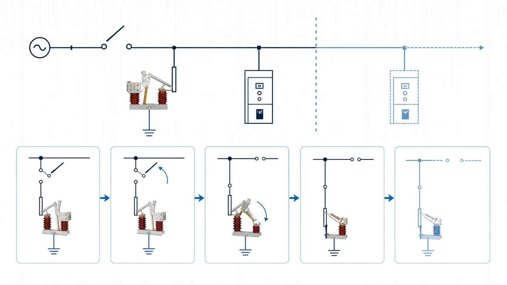
Engineering topology diagram for earthing switch isolation and maintenance grounding sequence
Ground after isolation

JN15, JN17 or GN22 cabinet grounding configuration

Use when the switchgear drawing already defines the isolation state, interlock and grounding operation side.

Withstand duty

Short-time current check

Review 40 kA, 4 s and 100 kA peak rating rows separately from the mechanical mounting layout.

Voltage class

Up to 33 kV after model confirmation

Confirm insulation level, short-time duty and installation drawing before release.

Selection matrix

Earthing Switch Selection Matrix

Use the matrix to pick the grounding configuration first, then check short-time duty, peak value, phase distance and cabinet interface.

Product type
Application point
Grounding interface
Project data
JN15 combined earthup to 33 kV
Switchgear grounding/Cabinet maintenance/Interlock sequence
Grounding shaft/Earthing blade/Phase distance rows
33 kV project class/40 kA / 4 s/Phase distance/Interlock state/Cabinet drawing
JN17 grounding switchup to 33 kV
Indoor grounding/Maintenance protection/Cabinet fit
Copper terminal block/Static contact/Open-hole layout
Short-time duty/Peak current/Install opening/Bus layout/Operation side
GN22 three-columnup to 33 kV
Grounding point/Structure reference/Project-specific fit
GN22 model/Three-column frame/Manual linkage
Voltage class/Short-time duty/Mounting drawing/Handle side/Quantity
Structure

Operating Shaft and Mounting

With the product type selected, check the earthing blade, contact travel, operating shaft, insulator set and mounting holes against the cabinet drawing.
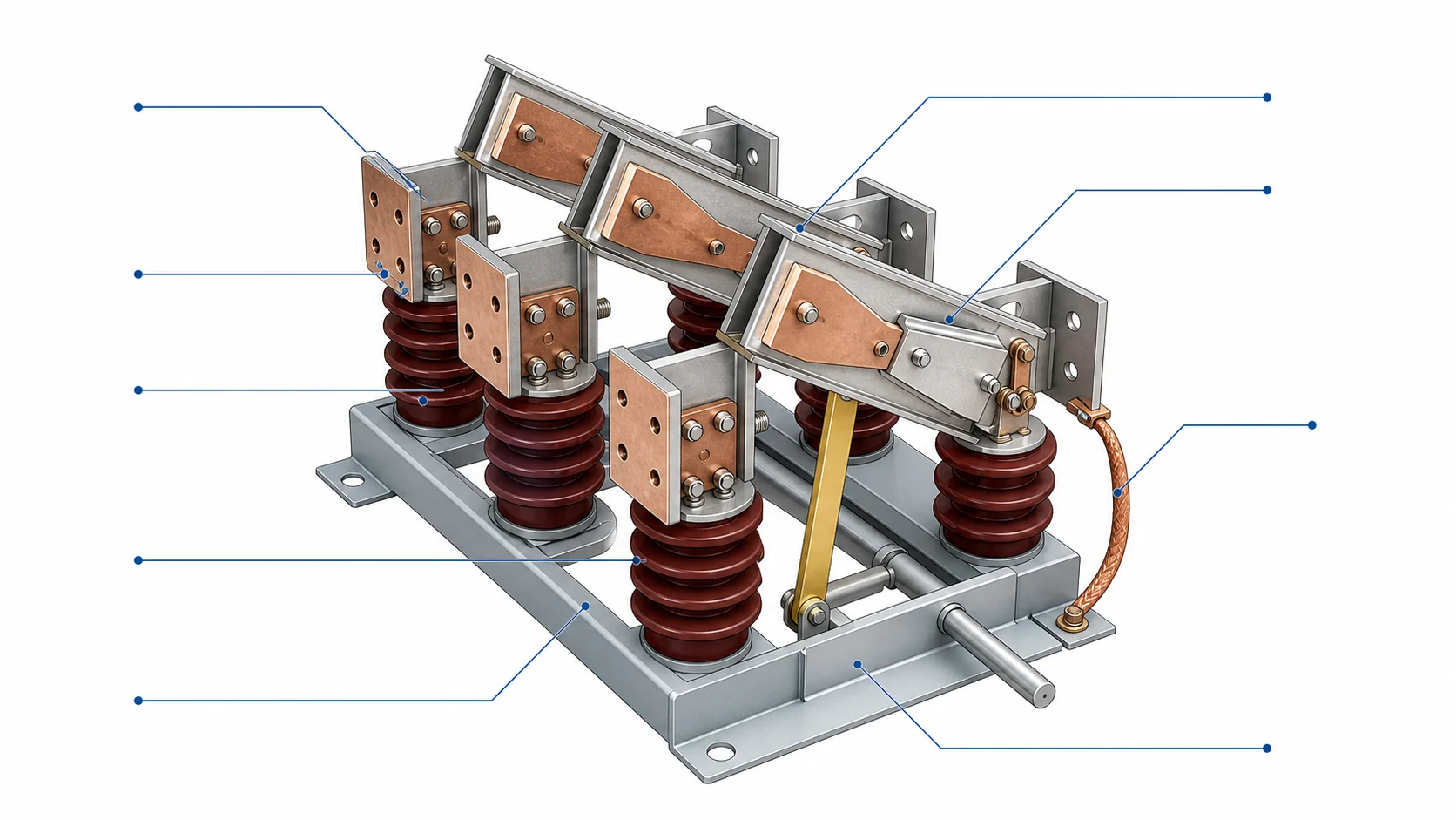
Structure schematic for earthing switch blade insulators operating shaft linkage and grounding conductor

Structure inputs

Use these four inputs before the model is released.

Grounding bladeBlade travel, static contact, copper bar and closed grounding position.
Operating shaftManual shaft, linkage arm, handle side and interlock interface.
Insulator and baseSupport insulators, base frame, terminal block and mounting holes.
Cabinet fitPhase distance, open-hole layout, bus position and panel drawing.
Variant handling

Short-Time Withstand Boundaries

Keep the 33 kV project capability, withstand rows and outline dimensions separate during engineering review.

Electrical boundary

Confirm the 33 kV project class separately from short-time duty.

JN15, JN17 and GN22 can be reviewed up to 33 kV. Use rating rows and order files for current, short-time duty and insulation level.

Drawing boundary

Review phase distance and opening layout before release.

JN15 includes phase-distance rows from 165 mm to 275 mm. JN17 includes 210 mm to 275 mm rows and cabinet opening references.

33 kV
Voltage capabilityJN15, JN17 and GN22 project review

Use the order file to confirm the final voltage class and insulation level.

40 kA
Short-time duty4 s duration with 100 kA peak row

Keep withstand duty separate from operating sequence and cabinet fit.

PD
Phase distance165-275 mm phase-distance rows

Use the cabinet drawing to confirm the real phase distance and opening layout.

Review files

Earthing Switch Documents

Separate clean product identity, rating rows, topology sequence and factory drawings. Do not expose mixed-label scans as drawing buttons. For broader document review, download earthing switch catalog PDFs.

JN17 indoor high-voltage grounding switch with copper earth bar and operating shaft
Clean grounding switch product image
Engineering topology diagram for earthing switch isolation and maintenance grounding sequence
Isolation and grounding sequence
Structure schematic for earthing switch blade insulators operating shaft linkage and grounding conductor
Structure points for drawing review
Product identity

Use clean product photos only

JN15, JN17 and GN22 images can identify structure, while scanned pages remain internal references.

Rating evidence

Separate voltage capability from withstand duty

All three product types can be reviewed up to 33 kV. Use rating rows or order files for current, 4 s duty and peak values.

Drawing boundary

Use clean English drawings where available

Cleaned Drawing tabs are used for JN15 and JN17; mixed-label technical scans stay internal.

Sequence file

Keep grounding sequence with interlock data

Isolation state, grounding position, operating side and cabinet drawing should be checked together.

Engineering selection

Earthing Switch RFQ Data

Lock the isolation state first, then check short-time withstand duty, interlock and mounting interface against the cabinet drawing. For procurement review, check certificates, test reports and RFQ forms before release.

01 / Isolation stateGround only after isolation is defined

Confirm the upstream open point and maintenance zone before selecting the earthing switch.

02 / Withstand dutyCheck short-time and peak current

Keep 40 kA / 4 s, 100 kA peak and insulation level in the engineering file.

03 / InterlockMatch operation to cabinet logic

Operating shaft, handle side and power display option must match the panel design.

04 / Mounting fitUse the drawing for release

Phase distance, terminal block, opening layout and bus position drive the final model.

Selection typeJN15 / JN17 / GN22.
System voltageUp to 33 kV project class or specified value.
Short-time duty40 kA / 4 s or required project value.
Peak current100 kA rating row or utility requirement.
Insulation levelPF withstand and lightning impulse values.
Phase distance165-275 mm phase-distance rows or cabinet drawing.
Operation sideManual shaft, handle side and interlock position.
Panel contextCabinet type, bus layout, opening drawing and quantity.
FAQ

Earthing Switch FAQ

What earthing switch data is needed for RFQ?

Send product type, system voltage, short-time withstand current, duration, peak current, insulation level, phase distance, cabinet drawing, interlock requirement, operation side and quantity.

Where is an earthing switch used in the isolation sequence?

An earthing switch grounds an isolated circuit or switchgear section for maintenance. It should be operated only in the approved isolation and interlock sequence.

How should engineers choose between JN15, JN17 and GN22?

Start with cabinet position, phase distance, interlock arrangement and mounting layout. All three product types can be reviewed up to 33 kV, but current, short-time duty and drawing release still need model-specific confirmation.

Is the three-column product GN22?

Yes. The three-column product shown in this selector is handled as GN22. GN10 remains an adjacent indoor disconnect reference and should not be mixed into the earthing switch selector.

When are earthing switch drawing views available?

Use public drawing buttons only where clean English outline drawings are available. If no clean drawing exists, include a factory drawing request with the RFQ.

Request Earthing Switch Quote

Send product type, system voltage, short-time withstand current, duration, peak current, phase distance, cabinet drawing, interlock requirement, operation side, quantity and destination standard. XIYA will return the suitable grounding switch configuration, drawing check and quotation scope.

Send Project Details
