Indoor disconnect switch types

Indoor Disconnect Switches for Cabinet Isolation and Three-Position Logic

Indoor disconnect switches are selected after the cabinet function is clear: no-load isolation, wall-through interface, bottom-outlet layout or three-position interlock. Compare GN19, GN27, GN30 and GN38 types by voltage class, current row, withstand duty, operating side and panel drawing.

Product types

Indoor Disconnect Switch Types

Start with the cabinet function. GN19 and GN27 are voltage-class isolating rows, GN30 handles rotary wall-through or bottom-outlet cabinet interfaces, and GN38 is reviewed as a three-position interlock type.
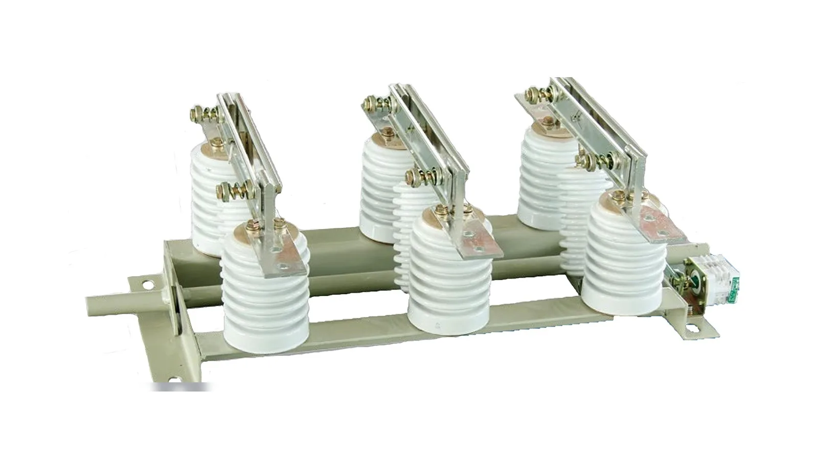
GN19 12 kV indoor disconnect switch with three phase knife blade contacts
ID 0112 kV cabinet isolation

GN19-12 Indoor Disconnect Switch

Indoor no-load isolating switch type for 12 kV switchgear where current row, withstand row and through-wall variant need confirmation.
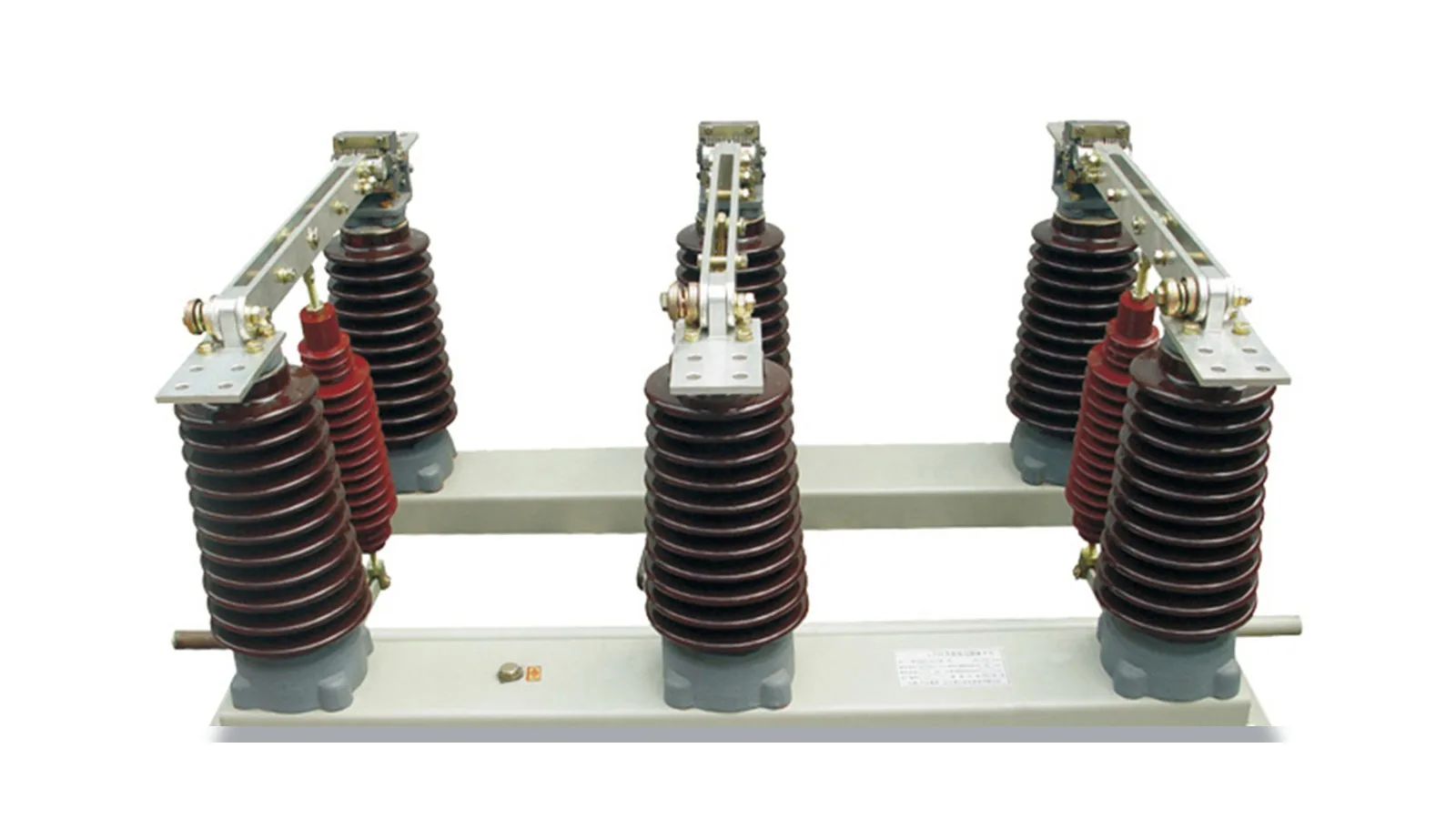
GN27 40.5 kV indoor isolating switch with post insulators and rotary knife blades
ID 0240.5 kV / 630-1250 A

GN27-40.5 Indoor Isolating Switch

Higher-voltage indoor isolating switch type for 40.5 kV switchgear where 630 A or 1250 A rows and 20 kA or 31.5 kA duty must be separated.
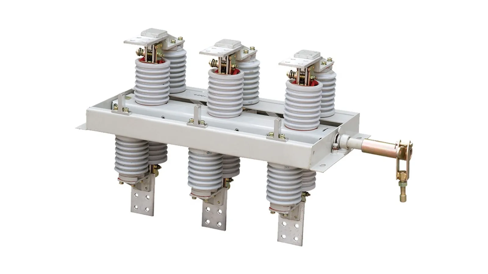
GN30 12 kV wall-through indoor disconnect switch on white background
ID 0312 kV wall-through

GN30-12 Wall-Through Switch

Double-insulated wall-through switch configuration where the disconnect body, bushings, shaft side and panel opening are checked together.
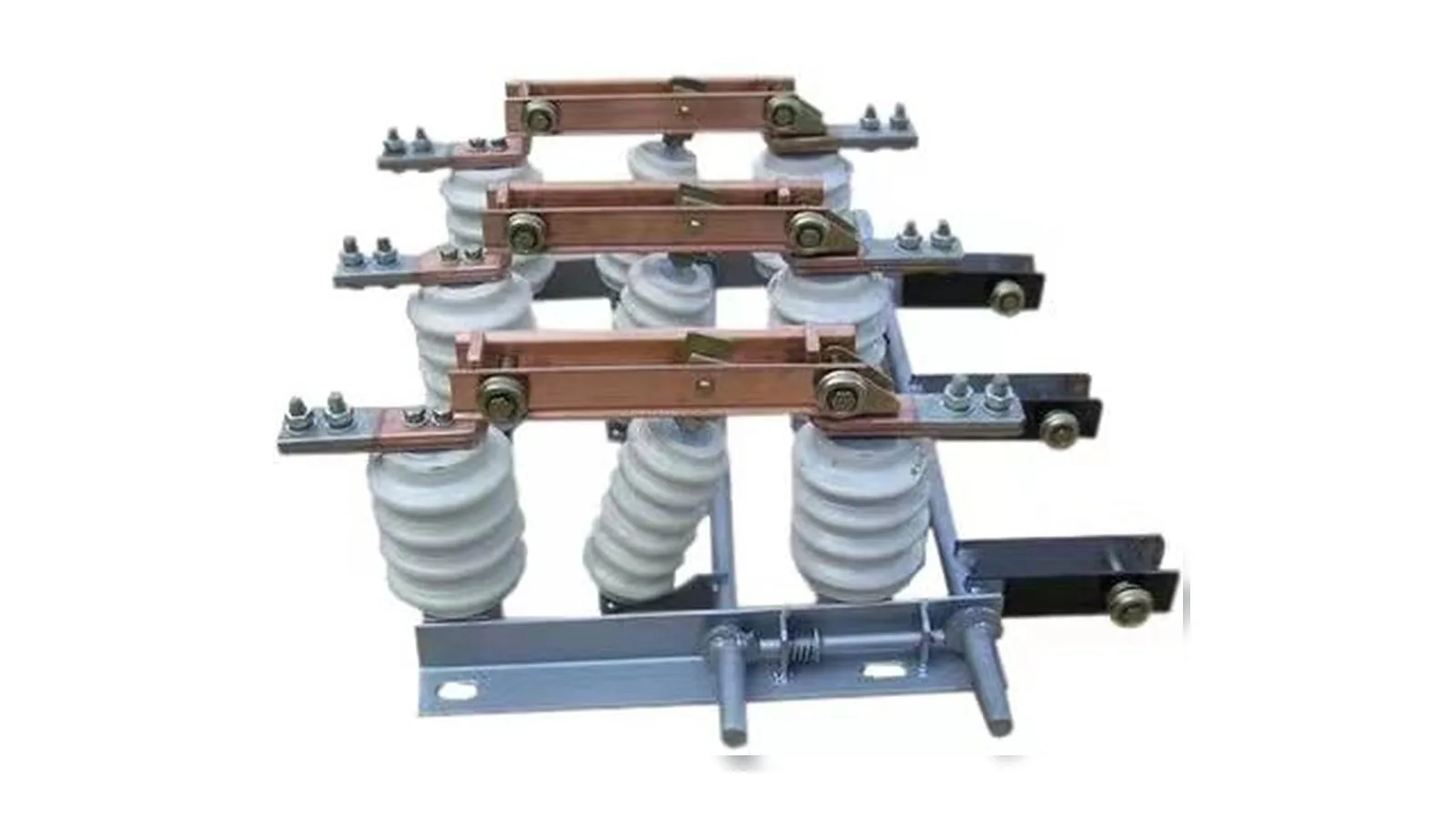
GN30 12 kV bottom outlet indoor disconnect switch product on white background
ID 0412 kV bottom outlet

GN30-12 Bottom-Outlet Switch

Double-insulated bottom-outlet configuration for compact cabinet layouts where the lower terminal direction and operating shaft boundary drive fit.
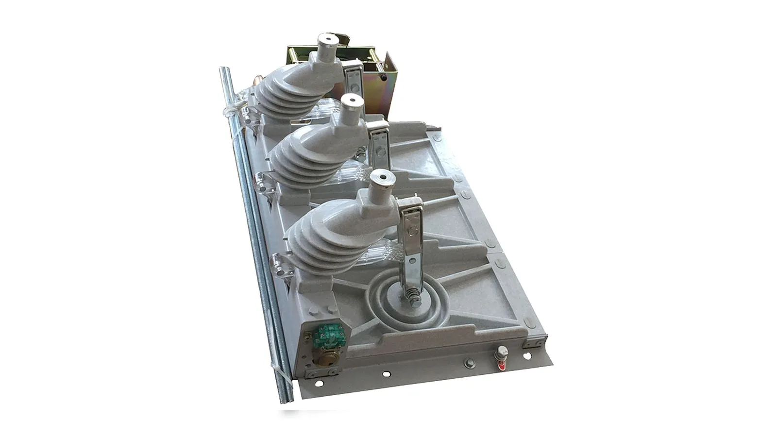
GN38 12 kV indoor three position isolator with integrated operating mechanism
ID 0512 kV three-position

GN38-12 Three-Position Isolator

Indoor three-position isolator type for compact switchgear where disconnect, isolated and grounding states must be reviewed with the interlock sequence.

Reference basisCabinet configuration selected by interface and interlock.

Use rating rows for GN19, GN27 and GN30 ratings, clean product images for product identity, and the GN38 technical page only within its stated 12 kV three-position boundary.

Rating rowsGN19, GN27 and GN30 tables support voltage, current and withstand comparison.
Clean product photosProduct cards use cropped or white-background images, not scanned pages.
Three-position boundaryGN38 requires state logic and interlock confirmation before release.
Project photo boundaryG.O. project photos show structure only and do not define ratings.
Technical parameters

GN19-12 Indoor Disconnect Switch Source Data

Catalog-based data from the GN19-12 indoor high-voltage disconnect switch pages in the supplied indoor switch folder.

Catalog referenceGN19-12 indoor high-voltage disconnect switch catalog rows

The GN19 source pages describe a three-pole indoor high-voltage disconnect switch for rated voltage 12 kV, AC 50 Hz and no-load isolation inside power systems.

The catalog text references a CS6-1 manual operating mechanism and notes through-wall C variants. Use the table for first selection, then confirm the cabinet drawing before release.

Rated voltage
12 kV
Rated current rows
400 A / 630 A / 1000 A / 1250 A
Rated short-time withstand current rows
16 kA / 20 kA / 25 kA / 31.5 kA
Rated peak withstand current rows
40 kA / 50 kA / 63 kA / 80 kA
PF withstand
42 kV to earth / 48 kV fracture
Lightning impulse withstand
75 kV to earth / 85 kV fracture
Creepage distance
300-380 mm source row
Mechanical life
2000 times

GN19 Electrical Rows

FieldSource value
Rated voltage12 kV
Rated frequency50 Hz
Rated current400 A / 630 A / 1000 A / 1250 A
Short-time withstand16 kA / 20 kA / 25 kA / 31.5 kA by model row
Peak withstand40 kA / 50 kA / 63 kA / 80 kA by model row

GN19 Cabinet Inputs

FieldWhat to check
Operating mechanismCS6-1 manual mechanism or panel integrated mechanism
Through-wall variantC, C1, C2 or C3 position from cabinet arrangement
Insulator and knife interfacePost insulator, rotary shaft, lever and wiring board
Release fileCabinet opening, shaft extension and operating side drawing
GN19 12 kV indoor disconnect switch with three phase knife blade contacts
GN19 product image cropped from catalog source, without catalog text
Catalog / sample basis

The catalog scan supports values and structure. The Drawing tab uses a cleaned outline-drawing crop without Chinese source labels.

GN19 outline and terminal drawings cleaned from the catalog source
Technical parameters

GN27-40.5 Indoor Isolating Switch Source Data

Catalog-based data from the GN27-40.5 indoor high-voltage isolating switch pages.

Catalog referenceGN27-40.5 indoor high-voltage isolating switch catalog rows

The GN27 source pages describe a 40.5 kV indoor isolation switch for rated 40.5 kV systems and no-load isolation duty.

Two visible rows are listed: 630 A with 20 kA / 4 s short-time duty, and 1250 A with 31.5 kA / 4 s short-time duty.

Rated voltage
40.5 kV
Rated current rows
630 A / 1250 A
Rated short-time withstand
20 kA / 4 s or 31.5 kA / 4 s
Rated peak withstand
50 kA / 80 kA
Lightning impulse withstand
185 kV to ground / 215 kV fracture
PF withstand
95 kV to ground / 115 kV fracture

GN27 Rating Rows

Model rowVoltageCurrentShort-time withstandPeak withstand
GN27-40.5/630-2040.5 kV630 A20 kA / 4 s50 kA
GN27-40.5/1250-31.540.5 kV1250 A31.5 kA / 4 s80 kA

GN27 Drawing Inputs

FieldWhat to check
Cabinet clearanceA, B and C dimensions from the project drawing
Installation formHorizontal, vertical or inclined mounting context
OperationCS6-2 mechanism or project operating mechanism
Environmental conditionIndoor polluted-place note from catalog must match site requirement
GN27 40.5 kV indoor isolating switch with post insulators and rotary knife blades
GN27 product image cropped from catalog source, without catalog text
Catalog / sample basis

Use the catalog rows for first-stage rating comparison. Use a clean project outline drawing for release if dimensions matter.

GN27 outline dimension drawing and terminal pad detail
Technical parameters

GN30-12 Wall-Through Switch Source Data

Catalog and clean product image basis for GN30-12 wall-through indoor high-voltage isolating switch selection.

Catalog referenceGN30-12 high-voltage isolating switch catalog table and wall-through product photo

The GN30 source pages describe a rotary indoor high-voltage isolating switch with a compact structure, fixed contact groups, moving rotary knife and optional earthing switch in the D variant.

Use the wall-through configuration when the cabinet needs through-panel bushings and a side shaft or handle interface.

Rated voltage row
10 kV
Highest voltage row
12 kV
Rated current rows
400 A / 630 A / 1000 A / 1250 A
Thermal stability current
12.5 kA / 20 kA / 31.5 kA
Thermal stability time
4 s
Dynamic current
31.5 kA / 50 kA / 80 kA
Impulse / PF level
75/85 kV impulse and 42/48 kV PF rows

GN30 Shared Rating Rows

FieldSource value
Rated voltage / highest voltage10 kV / 12 kV
Rated current400 A / 630 A / 1000 A / 1250 A
Thermal stability12.5 kA / 20 kA / 31.5 kA for 4 s
Dynamic current31.5 kA / 50 kA / 80 kA

Wall-Through Inputs

FieldWhat to check
Panel openingBushing hole, shaft hole and installation plane
Operating sideHandle position and shaft direction
Terminal sideThrough-wall terminal pad and busbar connection
Earthing optionD variant only when grounding function is confirmed
GN30 12 kV wall-through indoor disconnect switch on white background
GN30 wall-through switch clean product image
Catalog / sample basis

The wall-through photo identifies the cabinet interface. The Drawing tab shows the clean source outline drawing; final dimensions still require project confirmation.

GN30-12 wall-through appearance and installation dimension drawing
Technical parameters

GN30-12 Bottom-Outlet Switch Data Boundary

Clean product image basis for the bottom-outlet indoor disconnect switch configuration, reviewed against GN30 rating rows only when the project confirms the model.

Catalog referenceGN30-12 rating table plus bottom-outlet product photo

The bottom-outlet folder contains a clean product image showing a double-insulated indoor disconnect switch with lower outlet direction.

Use GN30 rating rows only when the order confirms the GN30 bottom-outlet form. Do not copy wall-through dimensions into the bottom-outlet package.

Product form
Double-insulated bottom-outlet indoor disconnect switch
Rating status
Use GN30 source rows after model confirmation
Visible interface
Lower outlet terminals, base frame, shaft and knife contacts
Selection requirement
Cabinet drawing, outlet direction, current row and operating side

Bottom-Outlet Review Boundary

FieldKnown detailStill needed
Outlet directionBottom outlet visible in product imageCabinet cable or busbar drawing
Current rowNot printed on product photo400 A / 630 A / 1000 A / 1250 A order row
Withstand rowNot printed on product photoThermal and dynamic current row from order file
Operating shaftShaft and mechanism visibleOperating side and interlock drawing
GN30 12 kV bottom outlet indoor disconnect switch product on white background
GN30 bottom-outlet switch clean product image
Catalog / sample basis

The photo supports structure and outlet direction only. It does not replace the order rating table or release drawing.

Technical parameters

GN38-12 Three-Position Isolator Data Boundary

Source-page and clean TIF product image basis for the indoor high-voltage three-position isolator type.

Catalog referenceGN38 / GNF38 three-position isolator source page and clean product image

The source page identifies a 12 kV indoor disconnect switch type with composite insulation, operating shaft and optional earthing function in the model designation.

The clean TIF product image is suitable for product identity. The supplied page does not provide a complete English rating table, so current and withstand rows must come from the order file.

Series basis
GN38 / GNF38 indoor disconnect switch source page
Voltage marker
12 kV in source model designation
Function review
Disconnect, isolation and grounding-state review
Visible structure
Insulated base, rotary shaft, linkage and operating mechanism
Data still needed
Rated current, withstand duty, interlock and cabinet drawing

Three-Position Selection Inputs

FieldWhat to check
Position sequenceClosed, isolated and grounded state logic
InterlockMechanical and panel interlock before release
Operating mechanismHandle side, shaft direction and cabinet access
Rating rowCurrent and withstand data from project order file
GN38 12 kV indoor three position isolator with integrated operating mechanism
GN38 three-position isolator clean product image
Catalog / sample basis

Do not infer the missing rating table from the product image or Chinese source scan. Request the order row before release.

Cabinet logic

Cabinet Isolation Applications

Indoor disconnect selection belongs inside the panel boundary. The cabinet drawing decides the isolation position, outlet direction, operating shaft and interlock sequence.

Cabinet role

Isolation is reviewed with the panel, not only the switch.

Check the incoming busbar, disconnect position, outgoing cable or busbar, optional grounding state and mechanical handle before choosing the product type.
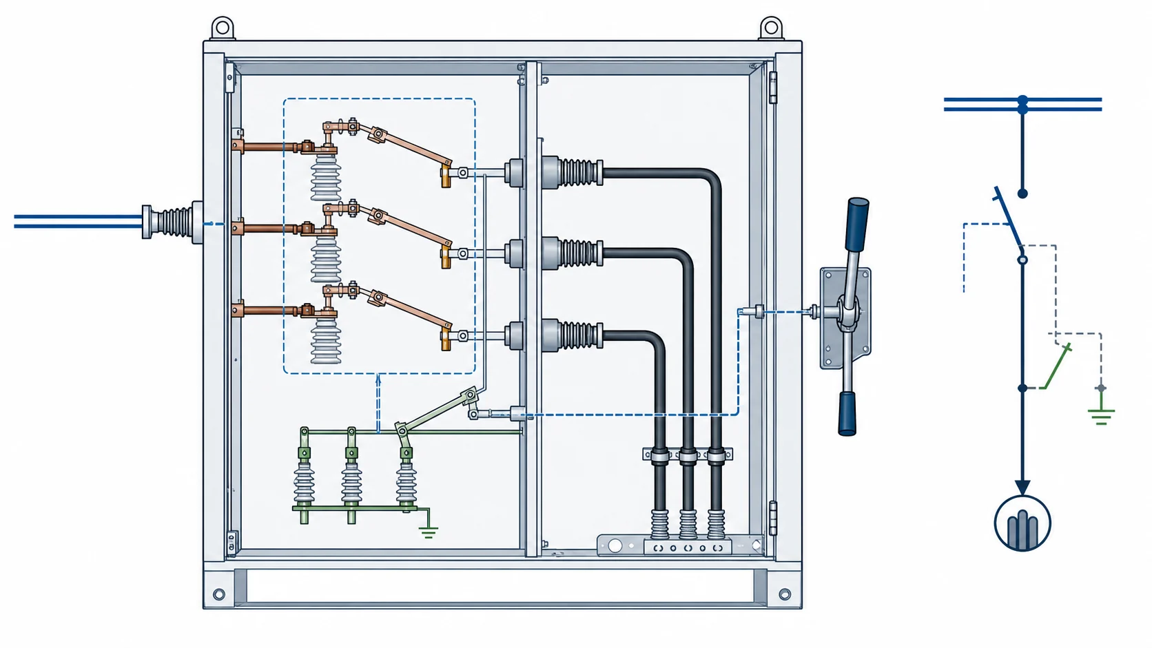
Engineering topology diagram for indoor disconnect switch cabinet isolation and three position sequence
Normal service

Closed circuit through the cabinet switch

Voltage and current rows must match the cabinet busbar and downstream feeder.

Isolated position

Visible isolation and interlock state confirmed

Use the drawing to check shaft position, access door interlock and safe operating sequence.

Grounding state

Three-position or D variant only when specified

Do not assume grounding function from a product photo. Confirm the model code and interlock logic.

Selection matrix

Indoor Disconnect Selection Matrix

Use the matrix to separate voltage class, cabinet interface and drawing inputs before choosing a product type.

Product typeCabinet functionPhysical interfaceProject data
GN19-12 isolation12 kV rows
No-load cabinet isolation/Through-wall variants/CS6-1 mechanism
Post insulators/Knife blade/Rotary shaft
Current row/Withstand row/C variant/Cabinet opening
GN27-40.5 isolation40.5 kV rows
Higher-voltage cabinet/630 or 1250 A/20 or 31.5 kA duty
Large post insulators/Rotary knife/Dimension row
Model row/A/B/C dimension/Operating mechanism/Clearance
GN30 wall-through10 / 12 kV basis
Panel bushing interface/Side shaft/Optional earthing D variant
Wall-through terminals/Rotary contact/Double insulation
Panel opening/Operating side/Terminal pad/Grounding option
GN30 bottom outletOrder row required
Compact cabinet outlet/Lower terminal direction/Project-specific fit
Bottom outlet/Knife contacts/Base frame
Outlet drawing/Current row/Withstand row/Interlock
GN38 three-position12 kV model row
Closed isolated grounded states/Interlock sequence/Compact switchgear
Three-position mechanism/Composite insulation/Operating shaft
State logic/Current row/Withstand row/Panel interlock
Structure

Shaft and Terminal Interfaces

After the product type is selected, confirm the moving blade, fixed contact, insulator class, shaft direction and terminal interface.
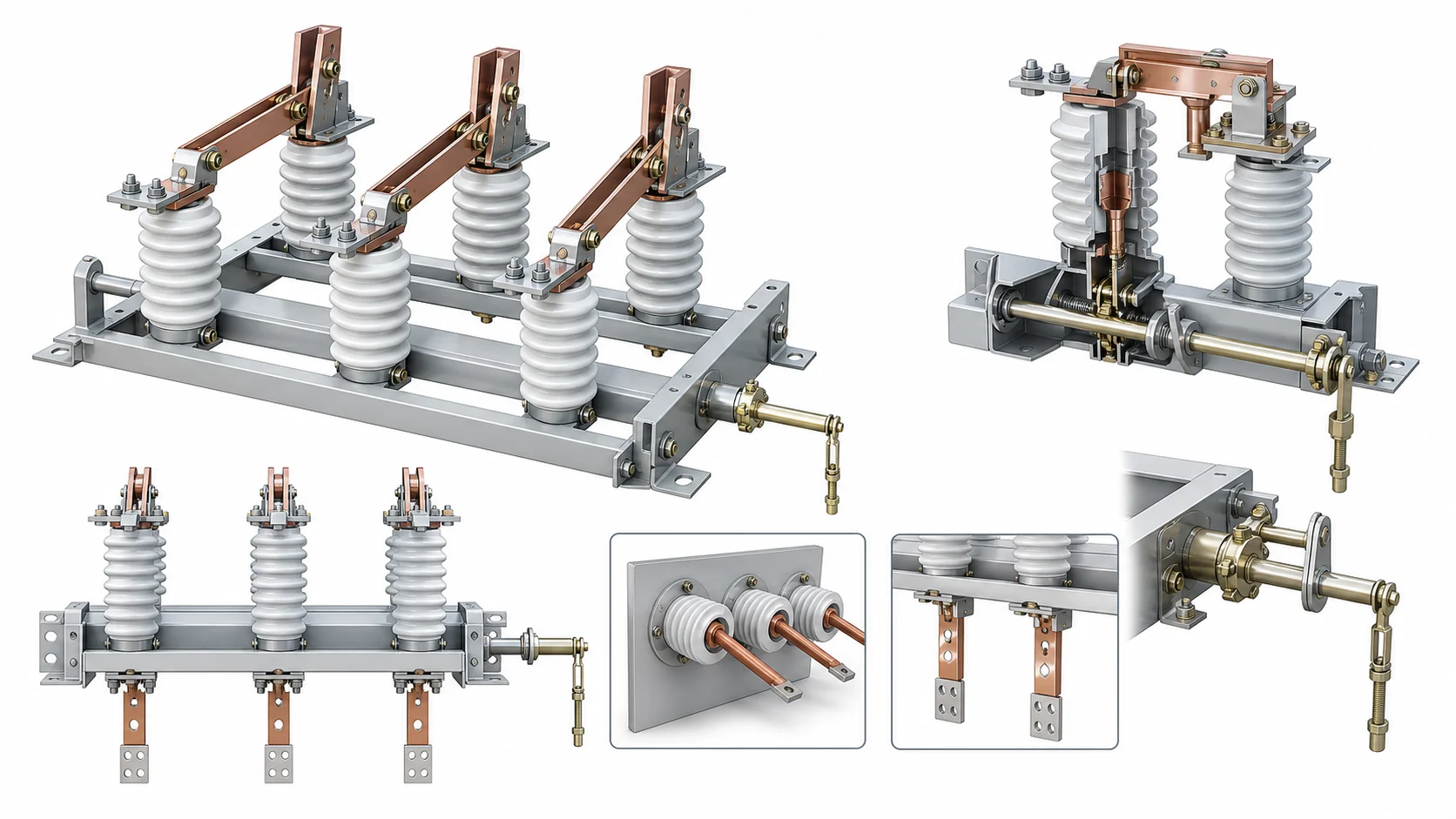
Structure schematic for indoor disconnect switch knife blade rotary shaft insulators and terminal interfaces

Structure inputs

Use these four checks before the model is released.

Knife blade and fixed contactOpen position, contact pressure, moving arm and fixed jaw contact.
Rotary shaft and mechanismCS mechanism, operating side, shaft extension and handle clearance.
Insulators and base framePost insulator, composite insulation, mounting holes and base frame.
Terminal interfaceWall-through bushing, bottom outlet, busbar pad or cable compartment fit.
Variant handling

Voltage and Cabinet Boundaries

Keep rating rows, cabinet interface and photo-only evidence separate. Do not copy dimensions or ratings across GN19, GN27, GN30 and GN38 types.

GN19 boundary

Use the 12 kV rows only for 12 kV cabinet isolation.

Current and withstand rows belong to the GN19 table and must match the through-wall variant.

GN27 boundary

Use 40.5 kV rows for higher-voltage indoor isolation.

630 A / 20 kA and 1250 A / 31.5 kA rows should not be mixed.

GN30 / GN38 boundary

Cabinet interface and state logic decide the final package.

Wall-through, bottom-outlet and three-position options need separate drawings.

12
GN19 rows400-1250 A and 16-31.5 kA rating rows

Use for 12 kV indoor isolation after cabinet variant is confirmed.

40.5
GN27 rows630 A / 20 kA or 1250 A / 31.5 kA

Keep current and withstand rows paired.

GN30
Cabinet interfaceWall-through or bottom-outlet drawing required

Do not copy outlet dimensions across variants.

GN38
State logicClosed, isolated and grounded sequence required

Order row and interlock drawing decide release data.

Review files

Indoor Disconnect Documents

Separate clean product identity, rating rows, cabinet topology and outline drawings. Expose Drawing tabs only where a clean English drawing is available. For broader file review, download indoor disconnect switch catalog PDFs.

GN38 12 kV indoor three position isolator with integrated operating mechanism
Clean three-position product image
Engineering topology diagram for indoor disconnect switch cabinet isolation and three position sequence
Cabinet isolation topology
Structure schematic for indoor disconnect switch knife blade rotary shaft insulators and terminal interfaces
Structure points for drawing review
Product identity

Use clean white-background product images

Product cards use cropped or processed images, not public scanned pages.

Rating evidence

Match each value to the right rating row

GN19, GN27, GN30 and GN38 boundaries stay separate.

Drawing boundary

Use clean English drawings where available

GN19, GN27 and GN30 wall-through include cleaned Drawing tabs; photo-only entries stay without Drawing buttons.

Project photo

Do not infer ratings from site photos

G.O. switch photos can show structure, not voltage, current or withstand rows.

Engineering selection

Indoor Disconnect RFQ Data

Lock the cabinet function first, then check voltage, current, withstand duty, outlet direction and interlock against the panel drawing. For procurement review, check certificates, test reports and RFQ forms before release.

01 / CabinetDefine the cabinet function

No-load isolation, wall-through, bottom-outlet or three-position interlock.

02 / RatingPair voltage and current rows

Do not mix 12 kV, 40.5 kV and photo-only evidence.

03 / InterfaceCheck physical outlet and shaft side

Panel opening, terminal pad and handle side drive fit.

04 / ReleaseConfirm drawing and interlock

State logic and cabinet drawing complete the request.

Product typeGN19 / GN27 / GN30 wall-through / GN30 bottom-outlet / GN38.
Cabinet functionNo-load isolation, wall-through, outlet or three-position interlock.
System voltage12 kV, 40.5 kV or project value.
Rated current400 A, 630 A, 1000 A, 1250 A or order row.
Withstand dutyShort-time current, peak current, PF and impulse rows.
Physical interfaceWall-through bushing, bottom outlet, busbar pad or cable side.
Operation sideMechanism, handle side, shaft extension and access direction.
Panel drawingOpening, dimensions, interlock, quantity and destination standard.
FAQ

Indoor Disconnect Switch FAQ

What indoor disconnect switch data is needed for RFQ?

Send cabinet type, voltage class, rated current, withstand duty, product type, operating side, interlock requirement, wall-through or outlet direction, panel drawing, quantity and destination standard.

Where is an indoor disconnect switch used?

It provides cabinet-level no-load isolation or isolator function inside switchgear. The selected type depends on voltage class, current row, mounting interface, operating side and panel interlock.

How should engineers choose between GN19, GN27 and GN30 types?

Use GN19 for 12 kV indoor isolation rows, GN27 for 40.5 kV rows, and GN30 when the cabinet interface is wall-through, bottom-outlet or rotary contact based.

Can GN30 wall-through data be copied into a bottom-outlet order?

No. Shared GN30 rating rows may support first comparison, but the bottom-outlet package needs its own outlet direction, cabinet drawing and order row.

When are indoor disconnect drawing views available?

Use public drawing buttons only where clean English outline drawings are available. If no clean drawing exists, include a factory drawing request with the RFQ.

Request Indoor Disconnect Quote

Send the cabinet type, product type, voltage, current, short-time and peak withstand duty, wall-through or bottom-outlet direction, operating side, interlock logic, panel drawing, quantity and destination standard. XIYA will return the suitable indoor disconnect type, drawing check and quotation scope.

Send Project Details
