Quotation form
Send an inquiry
Start with the basics. Our team can follow up for missing drawings, standards or packing details.
Submitted details are used only for quotation, technical review and project communication.
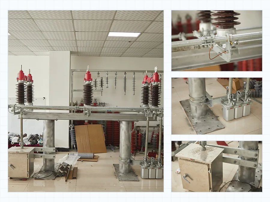
Compare seven outdoor disconnector structures for visible no-load isolation, neutral protection and outdoor line maintenance points. Use this page to choose the switch body, open-break geometry, mounting context and project data before model selection.
Start from the physical switch structure: rotary, single-pole, neutral gap, double-break, non-fuse, three-phase or V-type. Each product entry keeps the required project data beside the product options.
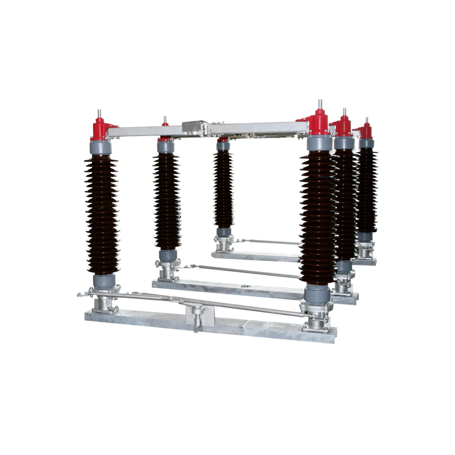
High-voltage outdoor visible isolation for substations, overhead line isolation points and maintenance switching positions.
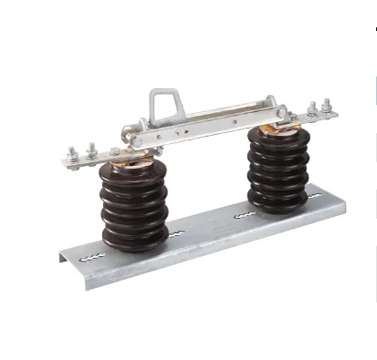
Medium-voltage single-pole isolation for overhead distribution lines where pole-by-pole switching and compact mounting matter.
Neutral-point isolation and gap-protection coordination for transformer neutral or special grounding arrangements.
Outdoor double-break isolation where the buyer needs a rotating contact arrangement and compact structure-based selection.
Single-phase non-fuse isolation for overhead line points where protection is handled by another device.
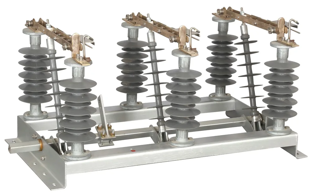
Three-phase outdoor disconnection for overhead line or structure-mounted isolation points.
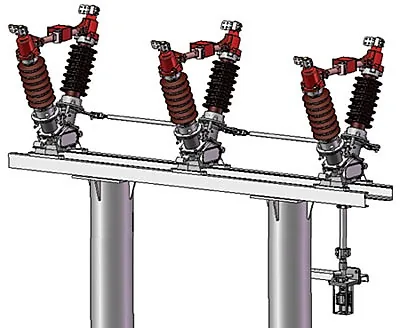
V-type or horizontal-break outdoor isolation for high-voltage line and substation positions with structure-specific clearance needs.
Select a product type, then send voltage class, rated current, operating method, mounting drawing, quantity and destination standard.
Outdoor disconnect switch selection starts with the isolation point: overhead line, substation structure, neutral point or pole-mounted maintenance point. Use this section to avoid mixing no-load isolation with load switching or fuse protection.
The topology board supports visual scanning. Final selection still follows voltage, current, mounting drawing and duty boundary.
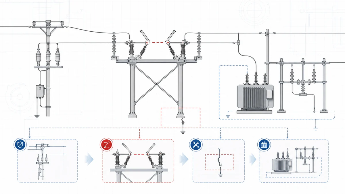
Use outdoor disconnect switches after load or fault current has been removed by upstream switching or protection equipment.
Double-column, rotary double-break and V-type structures are selected by voltage level, open distance, phase spacing and support structure.
Neutral disconnector with gap protection needs transformer neutral scheme, gap or arrester arrangement and drawing review before quotation.
Compressed engineering view: application point, structure signal and required project data. Product photos stay in the section above.
Confirm drawing, operation and mounting inputs before final configuration.
Four checks before final configuration.
After the switch structure is clear, confirm the rating, insulation material and duty boundary that change the final configuration.
15 kV, 33 kV, epoxy, polymeric and porcelain options stay under the single-pole isolation switch so the project data compares equal structures first.
Use outdoor disconnect switches for no-load isolation. Add fuse-combination or load-break requirements only when protection or current interruption is required.
A complete technical file lets engineering confirm structure, ratings, operating side and mounting clearance from more than product photos alone; teams can also download outdoor disconnect switch catalog PDFs before final model review.
Use product photos to identify double-column, single-pole, neutral, double-break, three-phase or V-type structures.
Send rated voltage, rated current, insulation level and insulator material so the selected model follows the right rating group.
Pole bracket, steel frame, phase spacing, terminal direction and operating side can change the final configuration.
If protection or load-current interruption is required, include that duty before final disconnect switch selection.
Send the selected structure with project ratings and mounting details so XIYA can confirm a buildable configuration before quotation, or check certificates, test reports and RFQ forms when project files need review.
Use this series when the line needs a visible open point after switching or protection equipment has cleared current.
Product type, visible isolation role and duty boundary are checked before recommending a model.
Photos identify the structure. Rating data and installation drawings narrow the final configuration.
Use the final form to send voltage, current, operation method and mounting conditions.
Start with the isolation point and switch structure. Then confirm voltage class, rated current, insulation material, operating method, mounting pattern and drawing inputs.
No. They are rating and insulation variants under the Medium Voltage Single-pole Isolation Switch. Select the structure first, then choose voltage class and insulator material.
Specify it separately when fuse protection and visible isolation are required at the same point. For simple no-load isolation, keep the selection under outdoor disconnect switches.
Send voltage class, rated current, line role, no-load isolation duty, phase layout, insulation material, grounding option, operating mechanism, mounting drawing, quantity and destination standard.
Outdoor disconnect switches are normally selected for visible no-load isolation. If the line point needs load current switching, compare outdoor air break switches or load break switch equipment before selecting the disconnect switch.
Send the selected product type with voltage class, rated current, no-load isolation role, phase count, insulator material, grounding option, operating method, mounting drawing, quantity and destination standard. For adjacent duties, compare the Disconnect Switches parent page, Outdoor Air Break Switches or Fuse Disconnect Switches before sending the final request.