Quotation form

Send an inquiry

Start with the basics. Our team can follow up for missing drawings, standards or packing details.

Contact Form Demo

Submitted details are used only for quotation, technical review and project communication.

Get Marketing Insights First
Subscribe to receive actionable strategies, growth tips, and industry insights delivered straight to your inbox.
Outdoor air break switch family

Outdoor Air Break Switches for Visible No-load Line Switching

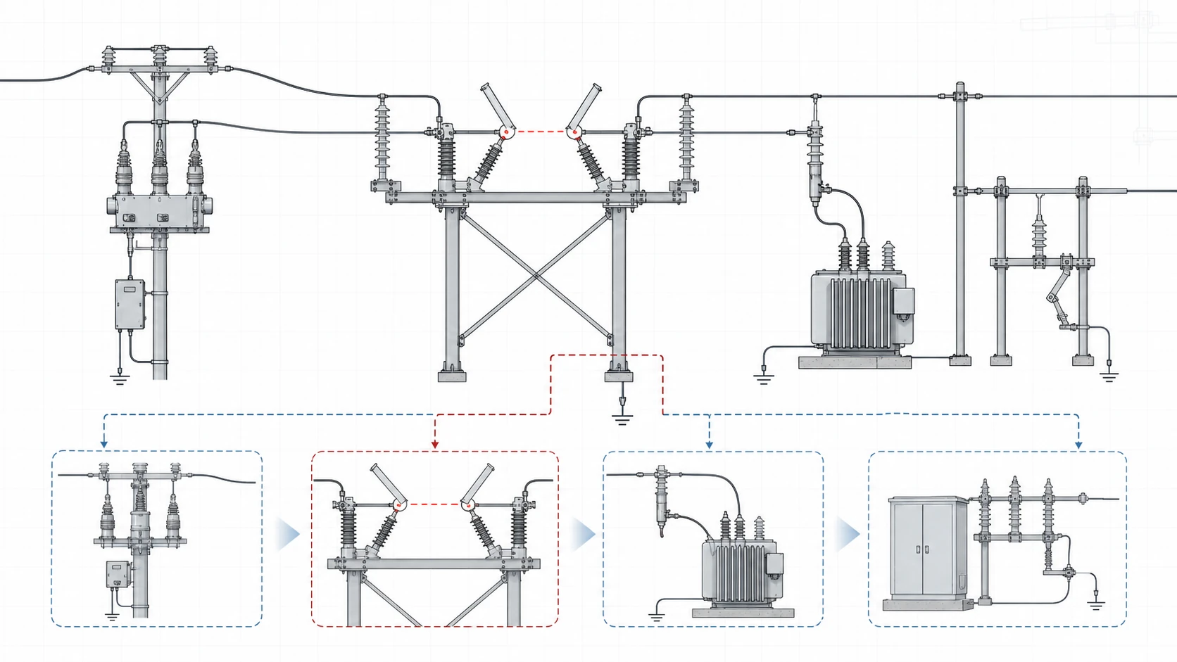
Compare four practical configurations for visible no-load isolation: standard RH-B gang ABS, arc-chute hardware, fuse-linked structure and RLND weatherproof grounding-knife duty. Check the switching role, voltage class, operation method and technical parameters before selecting a model.

4 selection configurationsRH-B, arc-chute, fuse-linked and RLND options map the application to the right hardware.
10 kV-36 kV reference rangeReference data covers 10/12 kV weatherproof duty and RH-B 11/24/33 kV air break switching.
No-load switching roleConfirm visible isolation before arc, fuse or grounding options.
Configuration categories

Outdoor Air Break Switch Configurations for Line Isolation.

Start with the hardware package the line point needs: standard RH-B visible isolation, arc-chute hardware, fuse-linked protection review or RLND weatherproof grounding-knife duty. This split keeps the selection focused on duty, rating and mounting inputs.

RH-B outdoor gang air break switch with three phase vertical opening structure
0111/24/33 kV

RH-B Outdoor Gang Air Break Switch

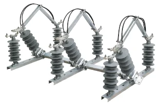
Standard RH-B three phase outdoor gang air break switch for visible no-load switching on 50/60 Hz distribution circuits.

Outdoor air break switch with arc chute option and porcelain insulators
02Arc chute option

Air Break Switch with Arc Chute

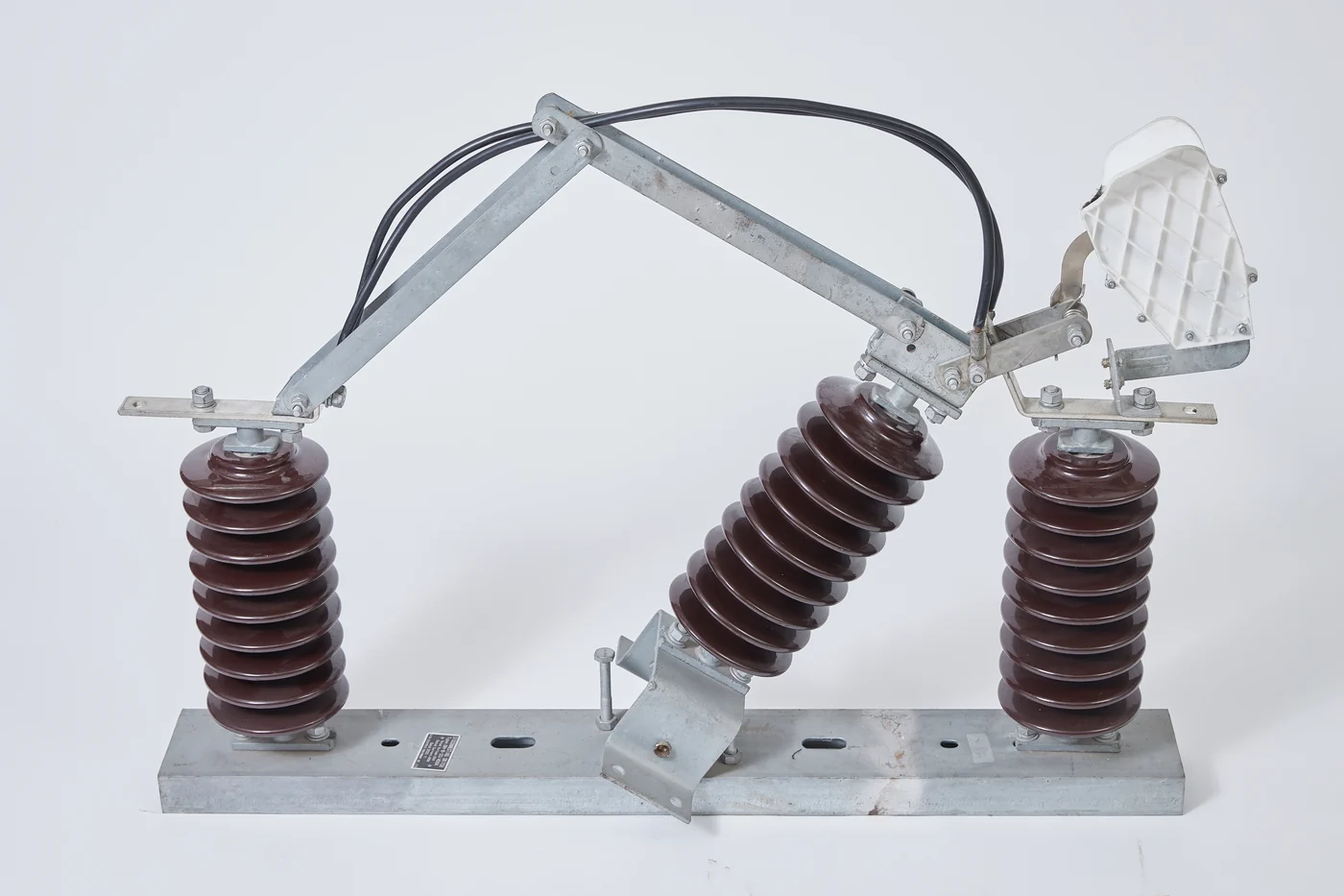
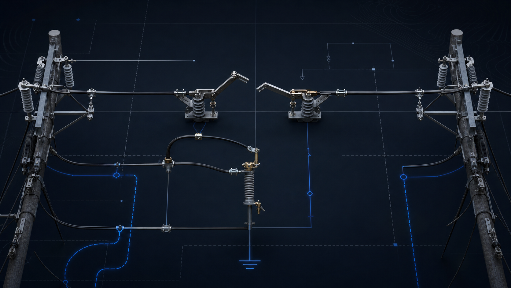
ABS configuration with visible arc chute hardware for projects that need contact-side and arc-control confirmation.

Outdoor air break switch with fuse option for protection and isolation
03Fuse option

Air Break Switch with Fuse

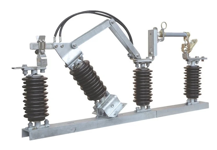
Fuse-linked ABS configuration for projects where visible isolation and fuse protection must be reviewed together.

RLND outdoor weatherproof disconnector switch with grounding knife structure
0410/12 kV

RLND Outdoor Weatherproof Switch

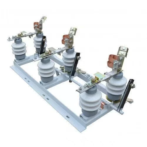
RLND outdoor two-column disconnector with grounding knife option for weather-exposed 10 kV line or substation use.

Technical parameters

RH-B Outdoor Gang Air Break Switch Technical Data

Technical parameter modal for the RH-B Outdoor Gang Isolator Switch instruction book.

Catalog referenceRH-B instruction book, model RH-B-11/24/33 kV

Outdoor AC gang isolator switch for 11 kV, 24 kV and 33 kV three phase AC 50/60 Hz circuits. The documented duty is switching on and off at voltage with no load.

The RH-B instruction book references GB1985-89 and IEC60129-1984. It lists porcelain and polymer insulator options plus manual and electric drivers.

Documented product
Outdoor Gang Isolator Switch, model RH-B-11/24/33 kV
Rated voltage
11 kV / 24 kV / 33 kV
Maximum voltage
12 kV / 24 kV / 36 kV
Rated nominal current
200/400 A at 11 kV; 400/630 A at 24 kV and 33 kV
Rated frequency
50/60 Hz
Operation
Single phase manual operation with manual and electric driver references

Main RH-B Parameters

ParameterUnit11 kV24 kV33 kV
Rated voltagekV112433
Maximum voltagekV122436
Rated frequencyHz505050
Rated nominal currentA200/400400/630400/630
4 s heat steady currentA125001250012500
Rated line charging breaking capacityA rms2.52.52.5
Rated cable charging breaking currentA rms101010
Rated transformer off-load breaking capacityA rms6.36.36.3
Impulse voltage to earthkV75135170
Impulse voltage across isolating distancekV95155195
Power frequency withstand to earthkV385570
Power frequency withstand across isolating distancekV426080
Rated short-time thermal stable currentkA162525
Rated short-circuit continuous times444
Rated peak dynamic stable currentkA405050
Mechanical lifetimes30001000010000
Manual operating torqueN.m<=200<=200<=200

RH-B Service Conditions

ItemDocumented value
Altitude<=1000 m
Ambient air temperature+40 C to -40 C
Wind pressure<=700 Pa, equivalent wind speed 34 m/s
Earthquake intensity<=8 degree
Ice thickness10 mm
Air pollution levelO ordinary type or II medium pollution
Maximum relative humidity95% at 25 C for humid tropical conditions
RH-B outdoor gang air break switch with three phase vertical opening structure
RH-B three phase outdoor gang air break switch
Outdoor air break switch units staged in the XIYA POWER workshop
Outdoor air break switch workshop stock reference
Catalog / sample basis

Parameters are taken from the RH-B instruction book. Check site mounting dimensions and operating mechanism requirements during technical selection.

Technical parameters

Air Break Switch with Arc Chute Configuration Review

Arc-chute configuration review for projects that need contact-side confirmation before final model selection.

Catalog referenceOutdoor Air Break Switch (ABS) / Air break switch with Arc photo group

The supplied arc-chute files show an ABS structure with arc chute hardware and contact-side details.

No separate arc-chute rating table is present, so electrical ratings should be tied back to the base ABS duty and confirmed with project line data.

Configuration role
Arc-chute hardware option under the Outdoor Air Break Switch (ABS) family
Visible product signal
Arc chute, moving contact side and porcelain insulator structure
Rating basis
Use RH-B voltage and current context unless a project-specific arc-chute data sheet is supplied
Project data
Confirm arc chute side, line duty, phase spacing, insulator type and opening direction

Arc-Chute Configuration Inputs

Review fieldConfirmed product signalTechnical follow-up
HardwareVisible arc chute assemblyConfirm whether arc-chute hardware is required for the line point
StructureThree phase outdoor air break structureConfirm phase spacing and contact orientation
InsulatorPorcelain insulator photos in the provided groupConfirm porcelain or polymer requirement
Duty boundaryConfiguration photo set onlySend line charging, no-load switching and utility standard requirements
Outdoor air break switch with arc chute option and porcelain insulators
Air break switch with arc-chute hardware main view
Side view of an outdoor air break switch with arc chute
Side view showing arc chute and contact side
Air break switch arc chute and moving contact detail
Arc chute and moving contact detail
Catalog / sample basis

The arc-chute material confirms structure signals but does not provide a standalone rating table. Use the base ABS ratings and project duty details for technical review.

Technical parameters

Air Break Switch with Fuse Configuration Review

Fuse-linked ABS review for projects where isolation and protection details must be separated clearly.

Catalog referenceOutdoor Air Break Switch (ABS) / Air break switch with fuse photo group

The supplied fuse image shows an outdoor air break switch configuration with fuse hardware.

Because protection selection depends on fuse link and carrier details, treat this as a configuration checkpoint before moving to fuse-disconnect selection.

Configuration role
Fuse-linked option under the Outdoor Air Break Switch (ABS) family
Visible product signal
Outdoor pole-mounted switch with fuse assembly
Voltage label
Photo label references 10 kV, 11 kV, 15 kV, 24 kV, 35 kV and 36 kV
Project data
Confirm fuse package, rated voltage, rated current, protection role and mounting method

Fuse Configuration Inputs

Review fieldConfirmed product signalTechnical follow-up
HardwareFuse assembly visible in the ABS product imageConfirm fuse carrier and fuse link requirement
Voltage context10 kV to 36 kV image label rangeConfirm exact system voltage and maximum operating voltage
Protection roleProtection plus isolation reviewDecide whether final selection belongs to air break switching or fuse disconnect switching
MountingOutdoor pole-mounted visual signalSend pole or frame drawing, phase spacing and terminal direction
Outdoor air break switch with fuse option for protection and isolation
Outdoor air break switch with fuse option
RH-B outdoor gang air break switch with three phase vertical opening structure
Base RH-B air break switch reference for comparison
Catalog / sample basis

The fuse material is a product photo, not a separate rating table. Confirm fuse carrier, fuse link and protection role before final selection.

Technical parameters

RLND Outdoor Weatherproof Switch Technical Data

Technical parameter modal for the Outdoor Weatherproof Switch specification PDF.

Catalog referenceOutdoor Weatherproof Switch specification, RLND outdoor two-column disconnector

The RLND outdoor two-column disconnector turns on and off de-energized 10 kV sections and grounds disconnected sections using stationary grounding knives.

The disconnector is a three-pole device. Each pole has one fixed and one movable column, and the movable column rotates 90 degrees in the horizontal plane.

Rated voltage
10 kV
Rated operating voltage
12 kV
Rated current
400 A / 630 A
Nominal frequency
50/60 Hz
Actuator
PRIZ-10 manual actuator reference
Service life
At least 30 years

RLND Technical Specifications

ParameterDocumented value
Rated voltage10 kV
Rated operating voltage12 kV
Rated current400 A, 630 A
Nominal frequency50/60 Hz
Short-circuit time for main knives / grounding knives3 s / 1 s
Direct current resistance of main current-carrying circuit<=130 x 10^-6 ohm
Permissible mechanical terminal load<=200 N with wind speed up to 15 m/s and 20 mm ice crust
Maximum force applied to drive handle3245 N
Leakage distance of external insulationNot less than 1000 cm
Power consumed by device per pole, RLND.1400 A – 13.2 W; 630 A – 15.3 W
Power consumed by device per pole, RLND.1.1400 A – 12.3 W; 630 A – 21.8 W

RLND Operating Conditions and Applications

ItemDocumented value
Ambient air temperature-60 C to +40 C
Atmosphere type and humidityType II industrial atmosphere, 80% relative humidity at 20 C
Installation heightNo more than 1000 m above sea level
Earthquake referenceMSK-64 scale 9 points context
Ice crust thicknessUp to 20 mm
Wind speed without iceNo more than 40 m/s
Wind speed with iceNo more than 15 m/s
Application examplesKTP substations, KSO chambers, KRu/KRUn switchgears, mobile substations, main distribution boards, capacitor units, input and distribution cabinets
RLND outdoor weatherproof disconnector switch with grounding knife structure
RLND outdoor weatherproof switch with grounding knife structure
Catalog / sample basis

Parameters are taken from the Outdoor Weatherproof Switch specification. Check interlock sequence, actuator package and mounting layout during technical selection.

Application fit

Feeder, Substation and Weatherproof Switching Applications.

Outdoor air break switch selection starts with the line role: a visible feeder open point, an arc-chute hardware option, a fuse-protection boundary or a weatherproof disconnector with grounding knife.

Engineering role

Place the air break switch after protection duty is clear.

Use the air break switch as a visible isolation or sectionalizing point. If the line needs load breaking, fault interruption or automatic reclosing, confirm the upstream breaker, recloser or fuse package before selecting this switch.

Engineering topology diagram for outdoor air break switch feeder sectionalizing fuse branch and grounding knife selection
Distribution line

Feeder sectionalizing points

Use RH-B air break switches for visible open points on 11/24/33 kV overhead distribution circuits after no-load duty is confirmed.

Substation interface

KTP and compact station use

Use RLND when the project needs a 10/12 kV outdoor disconnector, grounding knife and interlock context near a compact substation or input cabinet.

Protection boundary

Fuse package cross-check

When fuse protection drives the selection, confirm fuse carrier and fuse-link details before treating the air break switch as the final product path.

Selection matrix

Compare Duty, Structure Signal and Project Data.

Use this compressed view to match each configuration to its application point, visible structure and engineering data.

Configuration category
Application point
Structure signal
Project data
RH-B gang ABS11/24/33 kV
Feeder sectionalizing/Visible open point/No-load duty
Three phase gang/Vertical opening/Porcelain / polymer
Voltage/Current/Insulator/Drive method/Mounting
Arc-chute ABSArc chute option
Line charging review/Contact-side check/Outdoor line point
Arc chute/Moving contact/Opening side
Line duty/Arc side/Phase spacing/Insulator/Contact path
Fuse-linked ABSFuse option
Protection boundary/Transformer branch/Fuse cross-check
Fuse assembly/Outdoor pole mount/Air break body
Fuse carrier/Fuse link/Voltage/Current/Protection role
RLND weatherproof10/12 kV
Outdoor disconnector/Compact substation/Grounded section
Two-column/Grounding knife/90 deg rotation
400 A / 630 A/Grounding knife/Actuator/Climate/Mounting
Structure

Visible Break, Arc-Chute Hardware and Grounding Knife Boundaries.

Use the structure signal to separate isolation, arc-control, fuse-protection and grounding-knife duty before narrowing the model.

Visible isolation

Visible gap

Use this path when the project needs a clear open point on an overhead feeder after no-load duty is confirmed.

  • Open position
  • Contact travel
  • Isolation distance
Best matched to RH-B gang ABS.
Arc hardware

Arc-chute option

Keep this as a hardware confirmation point, not a separate rating family, unless a project data sheet says otherwise.

  • Arc chute side
  • Contact orientation
  • Opening direction
Check against base ABS ratings.
Protection boundary

Fuse-linked structure

Use this path only when visible isolation and fuse protection need to be reviewed together at the same line point.

  • Fuse carrier
  • Fuse link
  • Protection role
Compare with Fuse Disconnect Switches when protection leads.
Grounding duty

RLND grounding knife

Use RLND when the selection depends on outdoor 10/12 kV weatherproof disconnector duty and grounding interlock.

  • Grounding knife
  • Interlock context
  • Manual actuator
Best matched to weather-exposed substation points.
Variant handling

Voltage Ratings, Operation Package and Duty Boundaries.

After the switching role is clear, confirm the rating, operation package and hardware option that change the final switch configuration.

RH-B range

Choose voltage class and insulator material inside the RH-B family.

The RH-B document lists 11 kV, 24 kV and 33 kV rated voltage, up to 36 kV maximum voltage, and porcelain or polymer insulator options.

Weatherproof range

Use RLND for 10/12 kV weatherproof disconnector duty.

The RLND specification adds grounding knife and interlock context for outdoor 10 kV applications with 400 A or 630 A rated current.

RH-B rating band 11 / 24 / 33 kV

Use RH-B for gang air break switching on 50/60 Hz distribution circuits, with maximum voltage references of 12 / 24 / 36 kV.

200 A / 400 A / 630 A groups
RLND rating band 10 / 12 kV

Use RLND when weatherproof outdoor disconnector duty and grounding-knife interlock are the key selection signals.

400 A or 630 A
Operation package Manual / electric

RH-B references manual and electric drivers; RLND references a PRIZ-10 style manual actuator.

Confirm operating side
Hardware boundary Arc / fuse / ground

Treat arc chute, fuse assembly and grounding knife as hardware boundary signals, not interchangeable rating families.

Separate duty first
Technical inputs

Project Data for Air Break Switches.

Use four data groups to confirm the switch path before reviewing photos, drawings or mounting details.

Selection input pack4 checks
01ConfigurationRH-B / arc chute / fuse / RLND
02Electrical rating10-36 kV, 200-630 A
03OperationManual / electric / actuator
04InstallationPole, frame, phase spacing
No-load dutyVisible gapMounting check
Decorative engineering visual showing outdoor air break switch open gap, fuse branch and grounding path context
Product pathChoose the hardware family first.
Rating matchMatch rated voltage, current and frequency.
MountingConfirm bracket, terminal direction and operating side.
Duty boundarySeparate no-load, fuse, arc and grounding duty.
Technical checklist

Air Break Switch Selection Checklist.

Short fields for checking the selected configuration against the actual line point.

FirstDuty boundaryNo-load isolation, fuse branch, arc hardware or grounding knife.
SecondRating band10/12 kV RLND or 11/24/33 kV RH-B reference.
ThirdMounting packagePole, frame, terminal direction and operating side.
ConfigurationRH-B, arc-chute, fuse-linked or RLND weatherproof.
Voltage10 / 11 / 24 / 33 / 36 kV reference.
Current200 / 400 / 630 A reference.
Line roleFeeder, substation or branch point.
OperationManual, electric or PRIZ-10 actuator.
HardwareArc chute, fuse assembly or grounding knife.
MountingPole, frame, spacing, terminal direction.
QuantitySets, destination and utility standard.
FAQ

Outdoor Air Break Switch Selection FAQ.

Is an outdoor air break switch used for load breaking?

The RH-B document defines no-load switching; load current or fault duty should be checked against protection equipment first.

What project data should be checked before selecting a model?

Confirm voltage, current, frequency, insulator material, operation method, mounting and the required arc, fuse or grounding option.

When should I choose the weatherproof RLND switch instead of RH-B?

Use RLND for 10/12 kV weatherproof disconnector duty with grounding knife; use RH-B for 11/24/33 kV gang air break isolation.

Does the fuse option belong on this page or the Fuse Disconnect Switches page?

Keep it here when visible air break isolation leads; compare fuse disconnect switches when fuse protection leads.

Confirm the switch package.

Start with configuration, rating, operation and mounting. Compare adjacent pages only when the duty moves to disconnect-only or fuse-protection equipment.

Send Project Details