Quotation form
Send an inquiry
Start with the basics. Our team can follow up for missing drawings, standards or packing details.
Submitted details are used only for quotation, technical review and project communication.

Bypass disconnectors create a controlled alternate circuit around a recloser, breaker or line switching device during maintenance. Compare LW15, LW1 and project bypass configurations by voltage class, BIL, momentary duty, operation side and mounting layout.
Start with the equipment being bypassed. LW15 covers distribution-class disconnect or bypass rows, LW1 covers compact three-pull recloser bypass duty, and project photos need order-specific ratings.
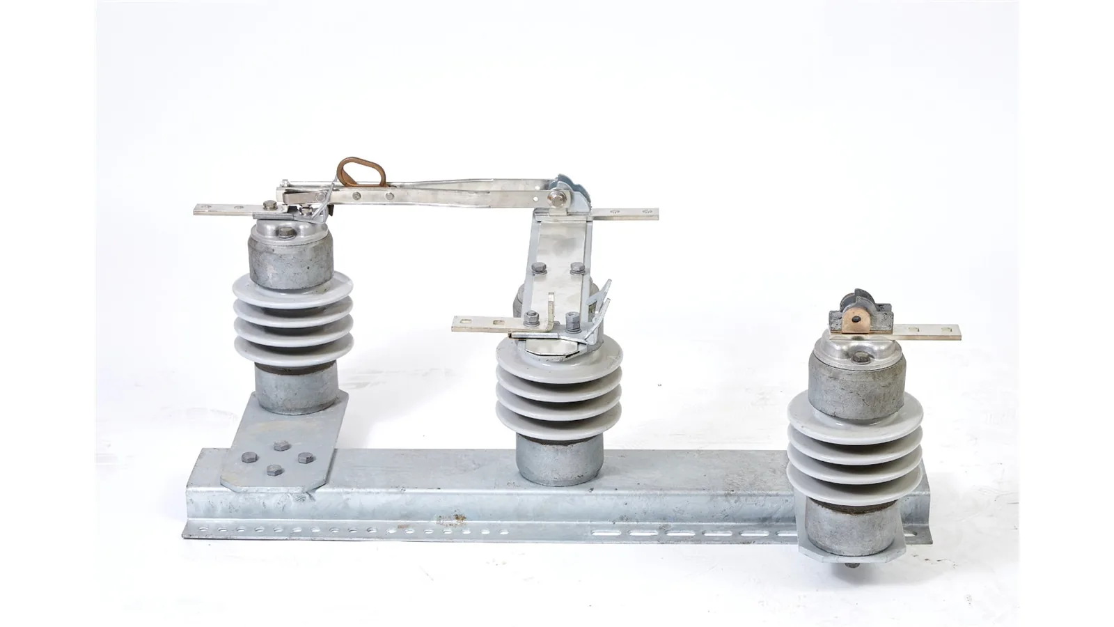
Distribution-class switch configuration for vertical or inverted cross-arm arrangements where bypass or disconnect duty is reviewed from the LW15 rating table.
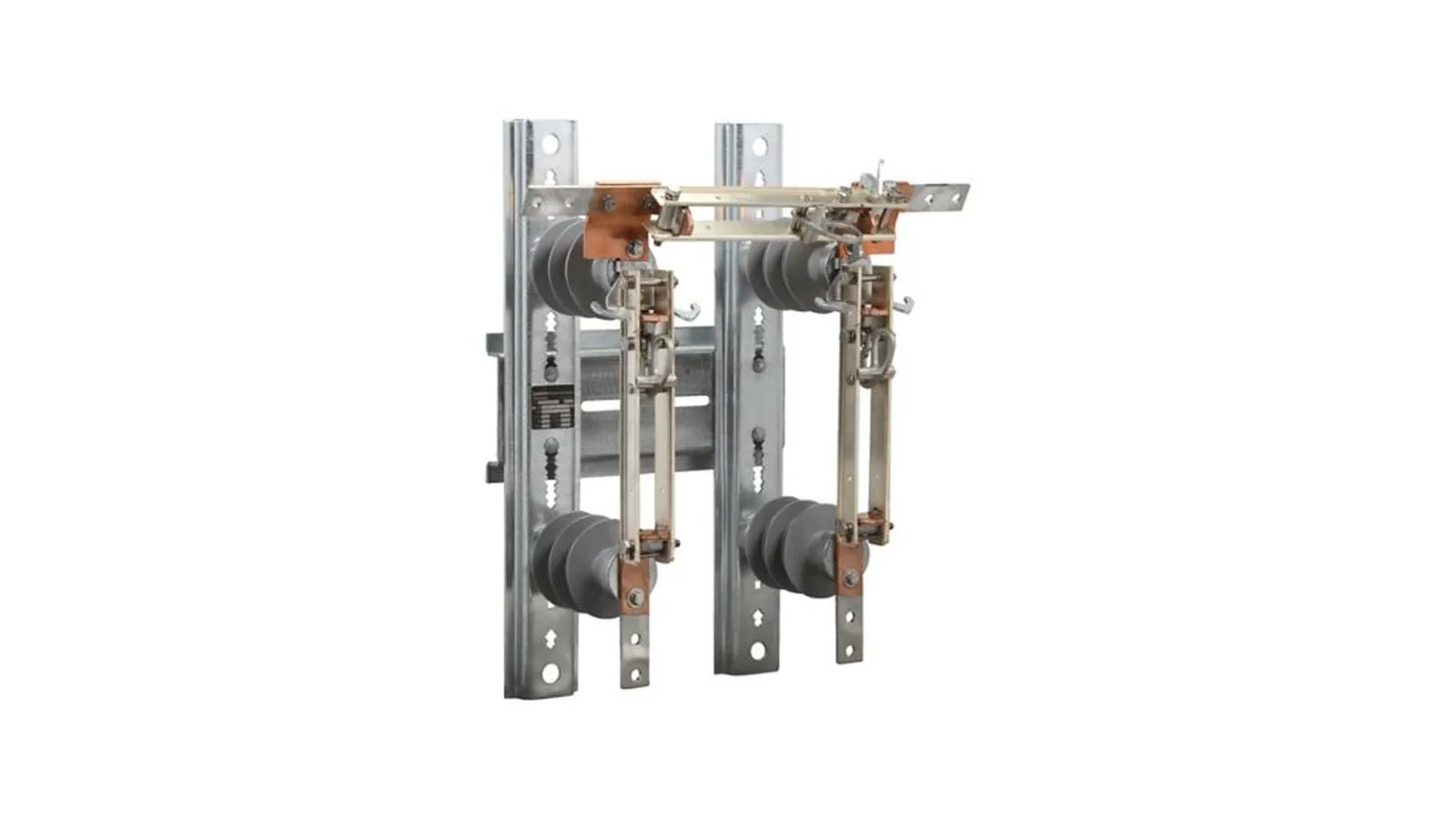
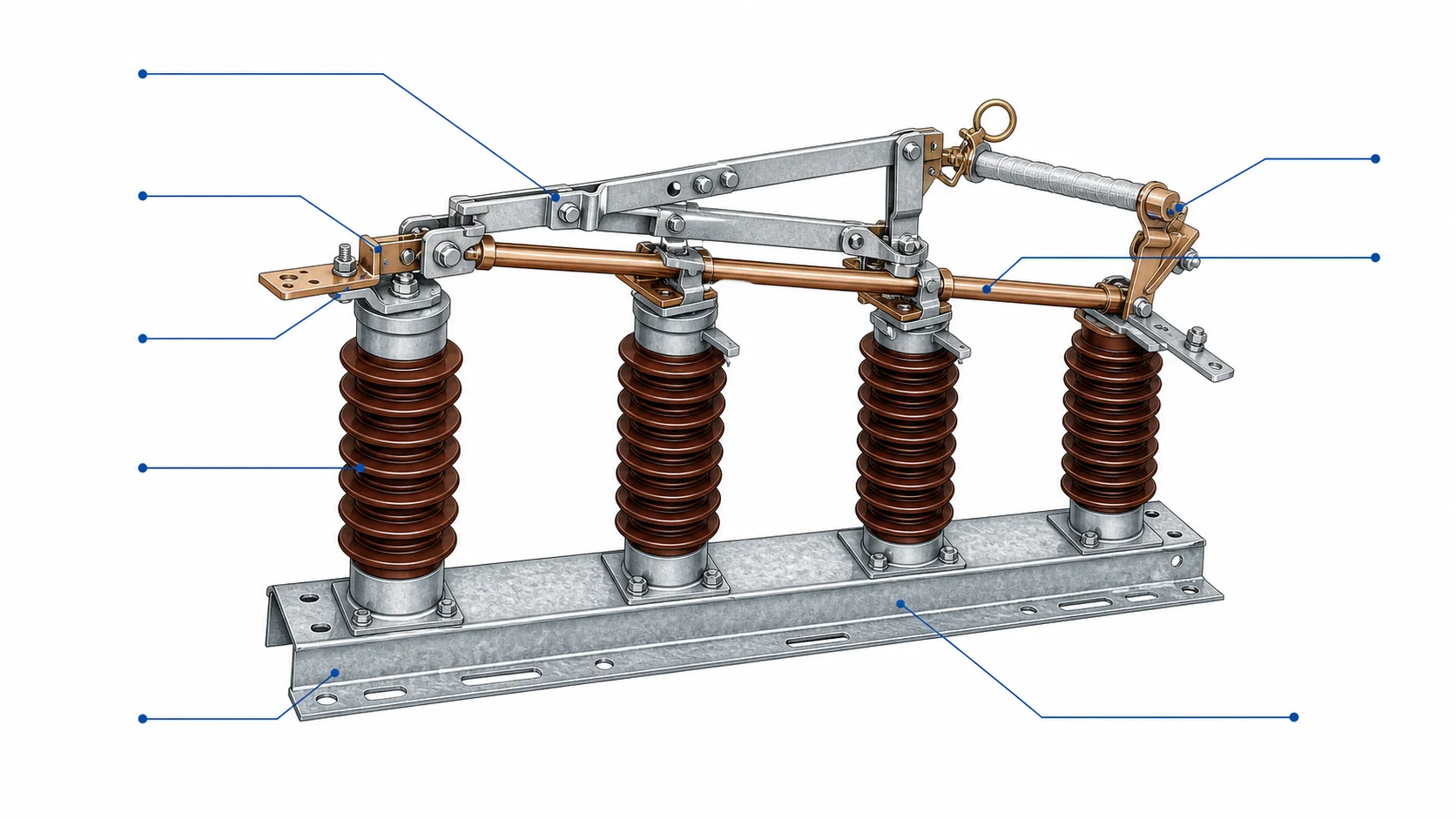
Compact three-pull bypass switch configuration for recloser or line device maintenance where the bypass blade spans the top terminals.
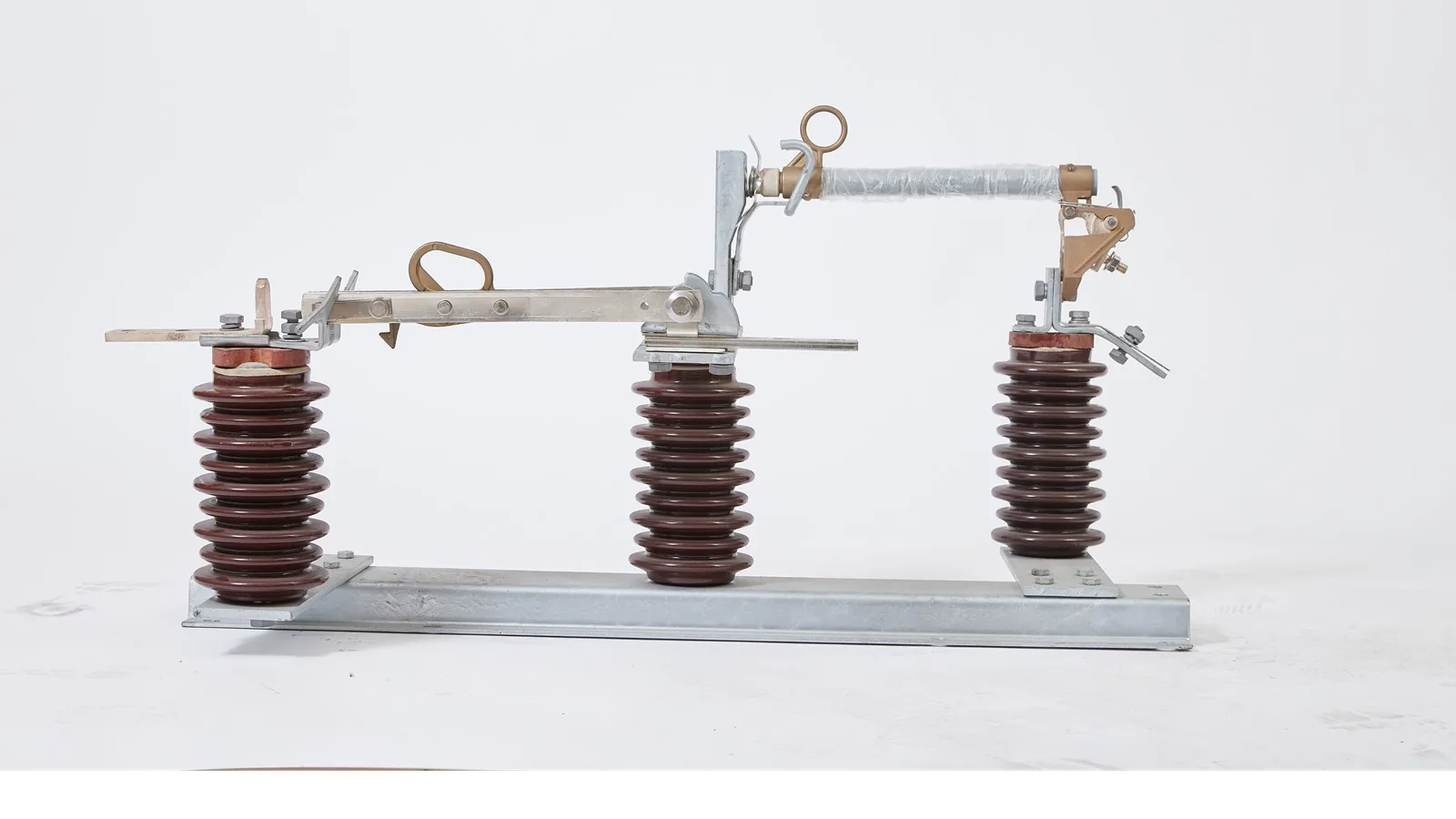
Project photo input for bypass disconnect assemblies where the layout, device being bypassed and operating sequence drive selection.
Use product photos, rating rows and project drawings for selection. Appearance references do not define voltage, BIL or momentary current.
Select the bypass disconnector after the protected device, normal position, bypass position and isolation sequence are clear.
Use this configuration when a recloser, breaker or line switch needs an alternate service circuit. If the duty is only visible no-load isolation, compare outdoor disconnect switches instead.
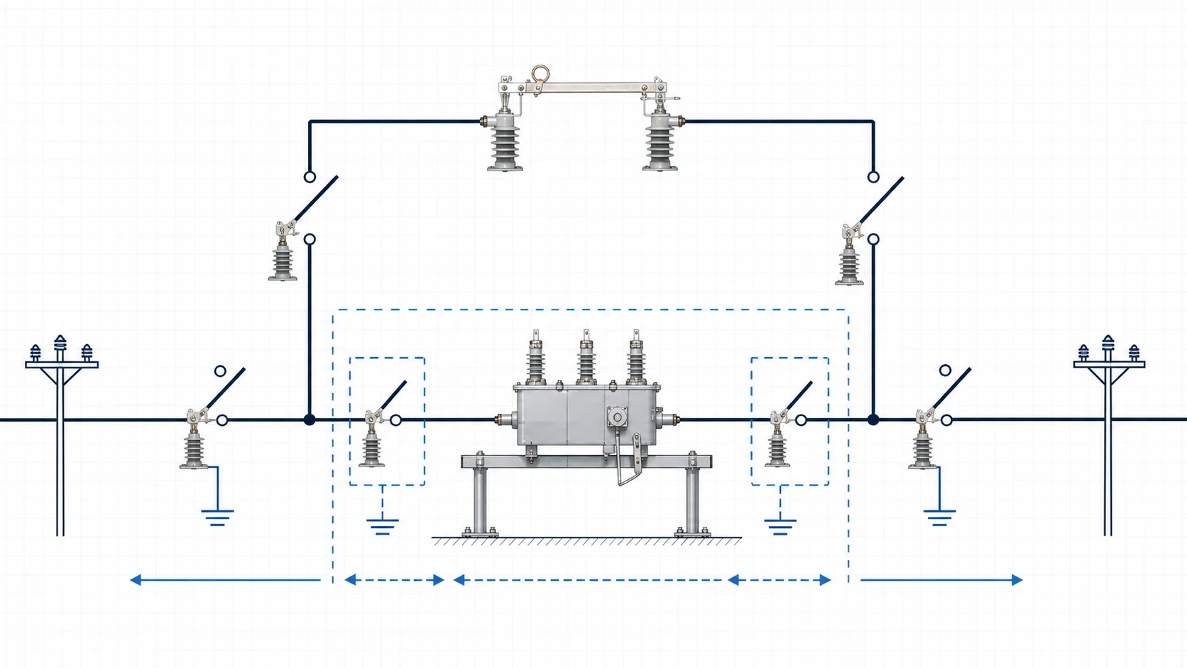
Confirm the equipment being bypassed and the normal operating position before choosing hardware.
Review bypass blade direction, disconnect position and the approved utility sequence together.
Mounting channel, cross-arm position, operation side and clearances must be checked from the site drawing.
Use the matrix to separate LW15, LW1 and project assembly configurations before checking voltage, current, BIL and momentary duty.
With the bypass sequence selected, check blade arrangement, hook-stick operation, insulator class and mounting channel against the drawing.
Use these four checks before the model is released.
Keep LW15 table values, LW1 bypass values and project photo-only data in separate engineering rows.
The 12.5 kA 4 s and 31.5 kA shock rows belong to LW15 first-stage comparison.
LW1 rows list 15.5, 27 and 38 kV classes, BIL up to 150 kV and 40 kA momentary current.
Separate clean product identity, rating rows, bypass topology and project drawings. LW1 now includes a cleaned Drawing tab from the supplied project PDF. For broader document review, download bypass disconnector catalog PDFs.
LW15, LW1 and project assembly photos identify structure without exposing technical scans.
Voltage, current, BIL and momentary values should not be copied across LW15, LW1 and photo-only assemblies.
LW1 uses the cleaned project PDF drawing. LW15 and project photo-only assemblies stay SPEC-only until clean outline drawings are supplied.
Bypassed equipment, normal position, bypass position, operation side and mounting drawing should be checked together.
Lock the bypassed equipment first, then check voltage, BIL, momentary duty and mounting sequence against the site drawing. For procurement review, check certificates, test reports and RFQ forms before release.
Recloser, breaker or line device position decides the bypass configuration.
Operation sequence must show when each disconnect and bypass blade is open or closed.
Keep LW15, LW1 and project-only values in separate rows.
Mounting channel, cross-arm, backstrap, direct bolting and operation side drive the final package.
Send the device being bypassed, system voltage, rated current, BIL, momentary current, normal and bypass sequence, operation side, mounting drawing, quantity and destination standard.
A bypass disconnector provides an alternate circuit around a recloser, breaker or line device so the equipment can be serviced according to an approved switching sequence.
Use LW15 rows when the disconnect or bypass duty follows the 15 kV or 24 kV distribution-class table. Use LW1 when the project is a compact three-pull recloser bypass arrangement with 15.5 kV to 38 kV design classes.
No. Project photos show layout, mounting channel and operating hardware only. Voltage, current, BIL and momentary duty must come from the order file or rating row.
Use product photos, rating rows, project drawings and the approved normal-to-bypass switching sequence. Appearance references do not define voltage, BIL or momentary current.
Send the bypassed device, voltage, current, BIL, momentary current, normal and bypass sequence, operation side, mounting drawing, quantity and destination standard. XIYA will return the suitable bypass configuration, drawing check and quotation scope.