Quotation form
Send an inquiry
Start with the basics. Our team can follow up for missing drawings, standards or packing details.
Submitted details are used only for quotation, technical review and project communication.

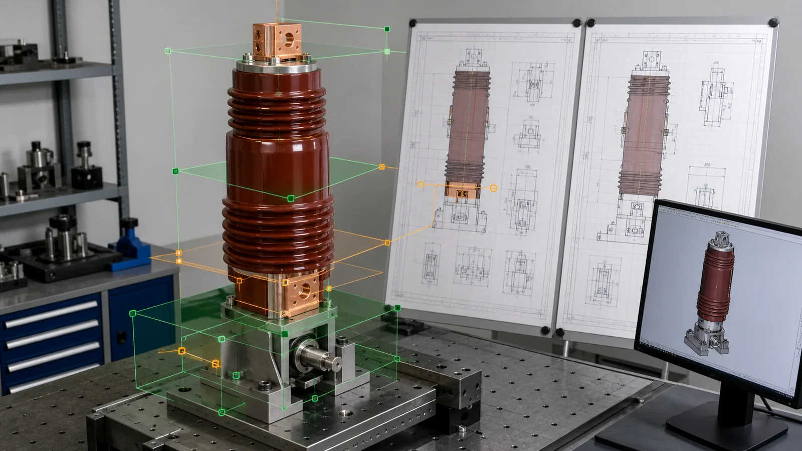
A vacuum pole assembly specification is reviewable only when the proposed part is tied to a controlled identity and revision, common datums and reference states, dimensioned interfaces, an insulation keep-out boundary, declared tolerances and notes, and configuration-applicable evidence. A photo, model label, nominal rating, or isolated dimension is only a screening input.
The practical release question is not whether two poles look similar. It is whether the project and supplier documents describe the same terminal, mounting, drive, insulation, and breaker/cabinet boundaries from a common technical basis.
Freeze the exact breaker and pole identity before comparing dimensions. Record the breaker series and variant, pole construction family, known part reference, electrical duty context, and the drawings or models that govern the review. The Switchgear Components pillar gives the family context, while the Vacuum Pole Assembly owner shows why several visually similar types still require drawing checks.
| Review layer | Controlled input | Supplier return | Release evidence | Hold condition |
|---|---|---|---|---|
| Identity | Exact breaker, pole and construction family | Proposed part and correspondence statement | Unambiguous configuration mapping | Generic VS1, rating or photo only |
| Document | Drawing/model number, revision, units and status | Supplier 2D/3D references | Agreed governing revision | Missing, obsolete or unmatched revision |
| Geometry | Critical features, datums, states and tolerances | Completed interface schedule | Common-basis comparison | Different origins or incomplete dimensions |
| Insulation | Construction and approved keep-out boundary | Profile and material declaration | Applicable cabinet/design evidence | Appearance used as insulation proof |
| Release | Approvals and deviation process | Assumptions and exceptions | Closed, signed disposition | Open or undocumented difference |
The controlled basis should identify units, projection, general and feature-specific notes, material references, revision history, and approval state. If a 3D model accompanies the drawing, record its file/version and which source governs when 2D and 3D differ. Do not silently combine dimensions from documents at different revisions.
Assign an owner to each required input. Breaker engineering normally owns the mechanism and frame basis, cabinet engineering owns the installed envelope, the supplier owns its proposed drawing and manufacturer data, and project authority owns deviations and technical release. The names vary by organization, but responsibility cannot remain implicit. A complete document list without a decision owner can still leave every interface unresolved.
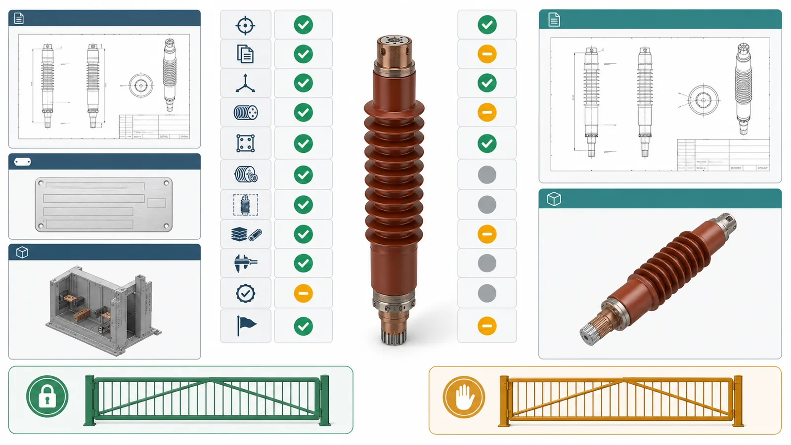
Two equal numbers are not necessarily equal interfaces. They may be measured from different faces, in different directions, or in different mechanism states. Each critical entry should therefore identify the feature, datum or datum system, direction, nominal value, tolerance, reference condition, measurement approach, and evidence status.
The official page for ISO 1101:2017 says the standard defines a symbol language for geometrical specification and rules for interpreting it. Its public abstract also notes visible indication and an alternative in which some specification information may be attached to a 3D CAD model. The project must state the adopted drawing/GPS standards and conventions; the public abstract does not provide project tolerances or acceptance rules.
| Critical feature | Required definition | Comparison risk | Release record |
|---|---|---|---|
| Terminal center/orientation | Datum, coordinates, axis and interface face | Same center value from another origin | Drawing comparison and disposition |
| Mounting pattern | Face datum, locating features, coordinates and insert details | Pattern rotated, mirrored or under-defined | Controlled feature schedule |
| Drive connection | Pin/rod axis, reference state and movement boundary | Coordinate taken in another state | Mechanism/pole interface drawing |
| Insulation envelope | Profile, orientation and cabinet keep-out | Overall size hides a local protrusion | Profile/envelope comparison |
| Pole/frame position | Pole spacing and breaker/cabinet coordinates | Chain accumulation or mixed revisions | Interface matrix and approved layout |
Check whether coordinates or chained dimensions are being compared, how tolerance accumulation reaches the mating feature, and whether hole, bore, thread, insert, profile, and orientation callouts are complete. A 3D shape can help visualize interference, but it does not replace missing tolerances, notes, material definitions, or approval status.
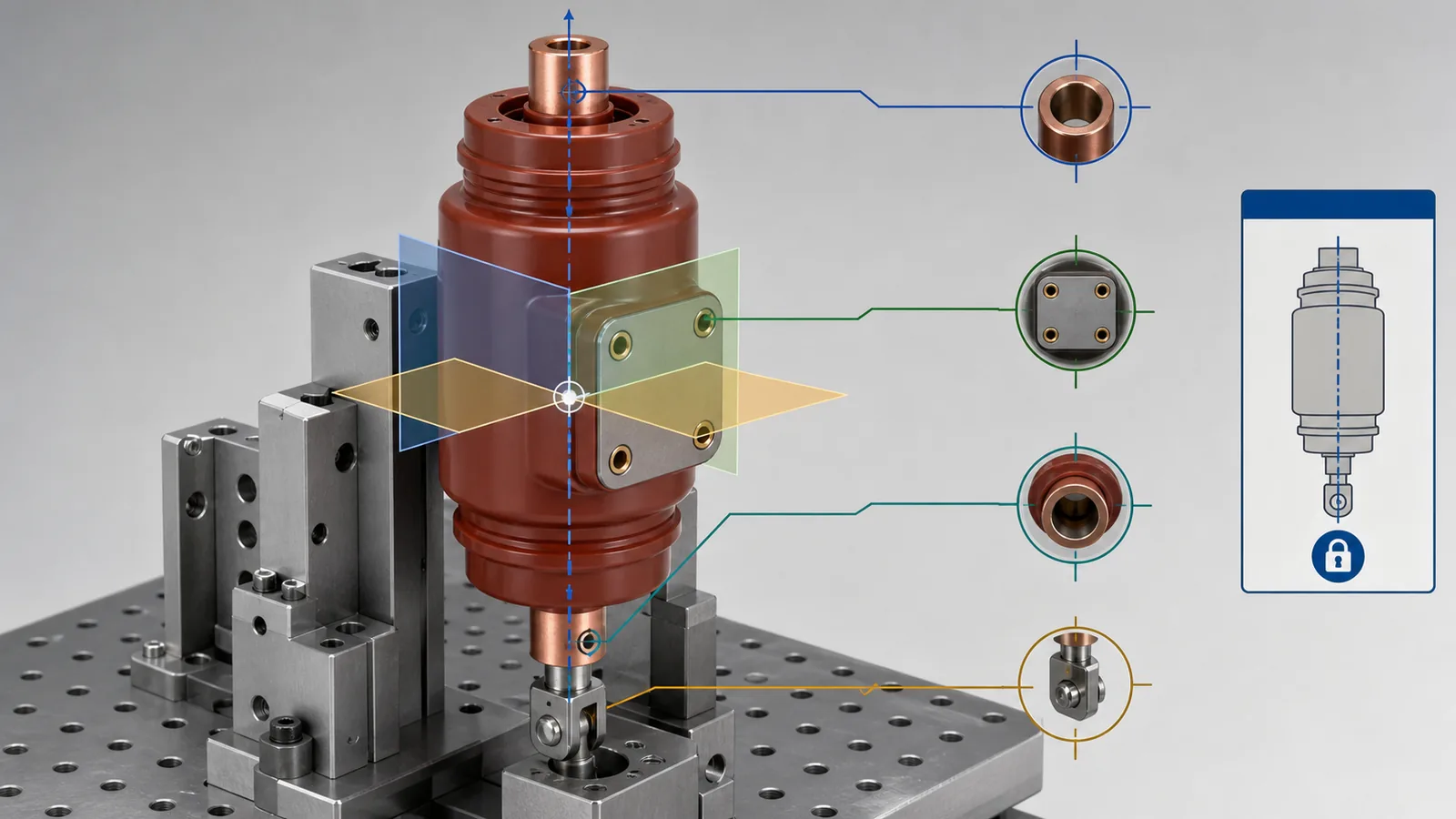
Review interfaces as a connected chain rather than a list of overall sizes.
Primary terminals: Identify upper and lower terminal coordinates, orientation, interface face, bore/hole/thread pattern, conductor connection boundary, and any drawing-controlled finish. Detailed contact-arm and tulip-contact selection remains in the contact interface matching guide; this review owns only the pole-side geometry and responsibility boundary.
Mounting: Define mounting faces, locating features, holes, embedded inserts, thread and depth information where required, orientation, and pole/frame coordinates. A matching outer profile does not compensate for an under-defined insert or a locating feature referenced from another datum.
Drive: Define the operating-rod or pin connection, axis, reference state, movement boundary, and relationship to the breaker mechanism. The coordinate is not reviewable if one drawing uses an open state and another uses a closed, unloaded, adjusted, or otherwise unnamed state.
Breaker and cabinet: Compare the installed pole envelope with the breaker frame, truck or fixed arrangement, primary contact approach, spouts, shutters, barriers, bus/conductor route, and maintenance access represented by the approved layout. This is where individually acceptable dimensions can still produce a collision or misalignment.
Do not prescribe a universal travel, torque, alignment tolerance, hole pattern, or hardware set. Those values belong to the exact controlled design. Drawing fit also remains separate from interrupter identity, electrical rating, and breaker-performance evidence.
The vacuum pole assembly foundation owns the component hierarchy and basic function. In a drawing review, insulation is handled as a configuration-specific boundary, not as a cosmetic profile.
| Evidence line | Review question | Suitable source | What it does not prove |
|---|---|---|---|
| Construction | Is the offered insulation family the approved one? | Controlled material/design declaration | Breaker performance |
| External profile | Does every local feature remain inside the approved envelope? | Pole and cabinet drawings/models | Dielectric acceptance by itself |
| Phase/earth boundary | Are adjacent phases, grounded structures and barriers represented correctly? | Approved cabinet insulation design | Universal clearance or creepage |
| Embedded hardware | Are inserts, conductors, brackets and bonded items located and defined? | Detailed pole drawing and material schedule | Manufacturing conformity without records |
| Environment interface | Is the surface path/design basis applicable to project conditions? | Project service conditions and design evidence | A universal pollution rating |
Review profile, orientation, conductive terminal and insert locations, grounded barriers, adjacent phases, cabinet structures, and any local protrusions. Where the design controls a keep-out boundary, compare the complete envelope, not just overall width and height. Do not infer universal clearance, creepage, dielectric, partial-discharge, or test values from a catalogue shape.
Maintain separate release lines for mechanical geometry, insulation-system applicability, electrical ratings/interrupter identity, and breaker-level performance. Closing one line does not close the others. A pole can fit a frame while remaining unsupported for the required electrical duty, or carry suitable ratings while failing a project-specific interface drawing.
Electrical suitability should trace to the approved breaker data, project specification, system duty inputs such as the short-circuit study where applicable, and configuration-specific qualification evidence. These sources do not supply proprietary interface dimensions; conversely, the pole drawing does not replace them. The release register should show which evidence source closes each requirement and which review authority accepted its applicability.

Revision control determines whether a completed review still applies. The switchgear component acceptance checklist covers broader incoming acceptance; this upstream release must first establish what the accepted part is supposed to match.
Use an RFQ and approval checklist that includes:
A measurement report is useful only when it maps results to the same features, datums, conditions and revisions used by the requirement. A report that lists overall sizes without the governing drawing basis does not close the interface matrix. Likewise, a redline records a difference; it does not approve it.
Set the release state feature by feature: matched, accepted deviation, rejected, or open. Any missing tolerance, unresolved model/drawing conflict, obsolete material reference, incomplete measurement coverage, or unsigned deviation remains a hold. When a drawing changes, review affected interfaces and downstream evidence rather than carrying the previous approval forward automatically.

Representative engineering review, not a XIYA POWER customer, factory, inspection, FAT, installation, commissioning, maintenance, or service case. All values are illustrative and non-universal.
Consider a proposed 12 kV withdrawable-VCB pole reviewed against released project drawing Rev B and supplier drawing S2. The documents appear to show an upper terminal center 214.0 mm from mounting datum A, a lower terminal bore center 86.0 mm from datum B, and a four-hole mounting pattern on 70 x 110 mm nominal centers. They also show an operating-rod pin center at 292.0 mm in a stated reference condition, 11.0 mm nominal movement, and an insulation keep-out envelope 178 mm nominal wide by 436 mm nominal high.
These values make the review concrete, but they do not establish a match. The submission remains on hold because the two drawings do not yet share a reconciled datum basis; all five features do not have comparable tolerance definitions; and the supplier’s operating reference state is not sufficiently mapped to Rev B. Insert/thread details and terminal orientation/finish are incomplete on S2.
The supplier’s 2D drawing and 3D model also need an agreed precedence rule, while the material/insulation reference must be aligned with the approved revision. No measurement report maps actual features to the controlled datums. Electrical ratings, interrupter identity, and breaker-level applicability remain separate open evidence lines, and no deviation has an approved disposition.
Release requires a common-datum translation, complete tolerance/state definitions, closed insert and terminal details, resolved 2D/3D and material revisions, a mapped measurement report, separate electrical/interrupter evidence, and signed deviations. No actual measurement, pass result, installation, test, or operating outcome is implied.
Include the exact breaker/pole identity, controlled drawings/models and revisions, datums, reference states, critical dimensions and tolerances, terminal/mounting/drive/cabinet interfaces, insulation boundary, material notes, measurement evidence, deviations, and release status.
No. Equal overall sizes can hide different datums, terminal orientation, mounting pattern, inserts, drive state, insulation profile, materials, or tolerances. Compare the complete controlled interface matrix.
The project drawing must declare them. Common review features include terminal coordinates/orientation, mounting and locating features, drive connection and reference state, insulation envelope, pole/frame position, and adjacent cabinet interfaces.
Compare the approved construction and complete external envelope with adjacent phases, grounded structures, barriers, embedded conductive hardware, and service-condition evidence. Do not derive universal electrical limits from shape alone.
No. Geometry, insulation-system applicability, electrical ratings/interrupter identity, and breaker-performance evidence are separate release lines. Each needs configuration-applicable support.
Control the project specification, approved project drawing/model, supplier drawing/model, interface matrix, material and insulation declarations, measurement plan/report, redline comparison, deviation register, approvals, and as-supplied revision record.