Quotation form
Send an inquiry
Start with the basics. Our team can follow up for missing drawings, standards or packing details.
Submitted details are used only for quotation, technical review and project communication.

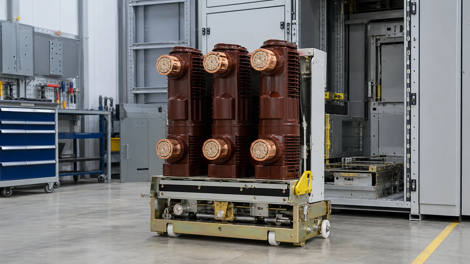
A vacuum pole assembly is the phase-by-phase primary switching component inside a medium-voltage vacuum circuit breaker (VCB). In a typical three-phase breaker, each phase has one pole. Depending on the design, that pole combines a vacuum interrupter with conductive terminals, insulation, mechanical support, and the moving-contact drive interface.
The vacuum interrupter extinguishes the arc. The pole assembly positions and insulates the interrupter, carries current to and from it, and connects its moving contact to the breaker mechanism. It is therefore neither the interrupter alone nor the complete VCB. A correct replacement must match the approved breaker data and drawings; a similar shape, voltage class, or VS1 label is not enough.
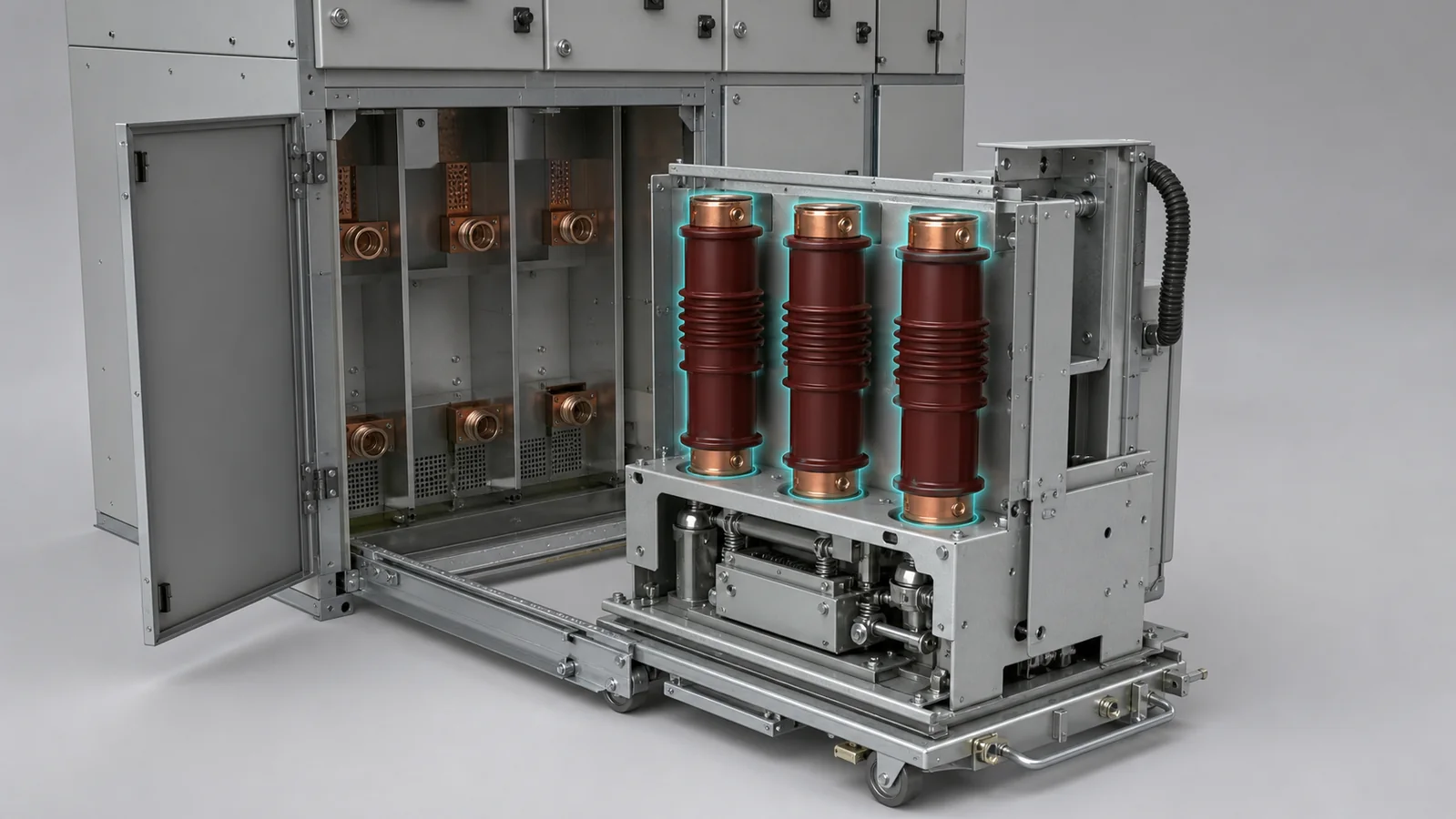
The component hierarchy matters because several related parts are often described as if they were interchangeable.
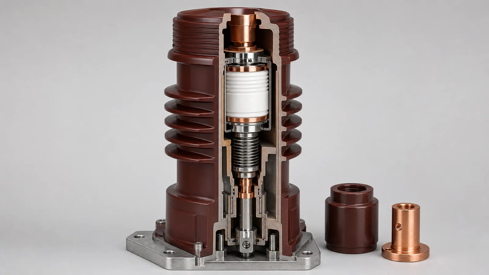
The interrupter is the sealed switching chamber. It contains fixed and moving contacts inside a high-vacuum envelope. A bellows permits contact movement while maintaining the seal. When the breaker opens, the contacts separate, the arc is controlled inside the vacuum envelope, and dielectric strength recovers after current interruption.
The pole assembly adds the structure needed to use that interrupter in one phase of a breaker. Its exact content varies, but it can include upper and lower primary terminals, conductive links, an epoxy insulation body or insulating cylinder, mounting features, and an operating-rod connection. The published XIYA POWER vacuum pole assembly range shows why product photos and drawings are both needed for initial matching.
The breaker mechanism supplies stored energy and moves all three poles through linkages. Opening and closing coils, latches, auxiliary contacts, interlocks, and the frame belong to the complete breaker rather than to one pole. The VCB then interfaces with the truck, primary contacts, secondary plug, protection system, and cabinet.
This distinction prevents a common procurement error: ordering an interrupter with the correct electrical description but without proving that its pole body and drive geometry fit the existing breaker.
A suitable pole assembly has four connected duties.
The public scope of IEC 62271-100:2021 covers AC circuit-breakers above 1 kV and complete-breaker performance and testing. It is an important standards reference, but it is not an interchangeability catalogue for internal pole dimensions. Compliance at breaker level does not prove that two pole assemblies from different manufacturers or design generations can be exchanged.
Two construction families are common in medium-voltage VCB work.
An embedded pole places the interrupter and associated conductive parts within a moulded insulation body. The casting provides insulation and structural support while controlling the external profile and mounting interfaces. Because the assembly is highly integrated, replacement normally starts from the complete pole part number and breaker drawing.
An insulated-cylinder design uses a separate insulating cylinder or support arrangement around the interrupter and conductive path. Access, fastening, insulation geometry, and service procedure can differ from an embedded pole. Whether an interrupter can be serviced separately depends on the approved product design and OEM instructions.
These names describe construction approaches, not universal dimensional standards. Two assemblies can share a nominal voltage and current yet differ in terminal position, pole pitch, fixing pattern, insulation profile, or drive connection. The broader switchgear components family is useful for understanding adjacent contact and insulation interfaces, but final selection still belongs to the breaker-specific drawing set.
Replacement review should treat the pole as an electrical, insulation, mechanical, and cabinet interface at the same time.
| Interface | What to confirm | Approval source |
|---|---|---|
| Breaker identity | Manufacturer, exact series, frame or generation, serial/nameplate data | Breaker nameplate and equipment register |
| Electrical duty | Rated voltage, normal current, frequency, short-circuit duty and any project-specific sequence | Approved breaker data sheet and project specification |
| Primary terminals | Upper/lower orientation, hole pattern, contact arrangement and conductor connection | Pole and breaker assembly drawings |
| Insulation envelope | External profile, phase spacing, earth clearance and cabinet barriers | Approved outline and cabinet drawings |
| Mounting | Flange, fixing holes, locating features, datum surfaces and pole spacing | Controlled drawing revision |
| Drive interface | Operating-rod connection, alignment, travel and adjustment method | Mechanism drawing and OEM manual |
| Cabinet fit | Truck envelope, spouts, contacts, shutters, barriers and busbar approach | Breaker and cabinet interface drawings |
The medium-voltage circuit breaker category provides the complete-device context. For a withdrawable breaker in a KYN28 metal-clad cabinet, the pole also has to remain compatible with the truck, contact system, shutters, interlocks, and available insulation clearances.
Use the following troubleshooting chart as triage, not as an automatic instruction to replace the pole. Work only under the site’s approved de-energized, isolated, earthed, and access-controlled procedure.
| Observed symptom | First test or review | Likely cause category | Next action or evidence |
|---|---|---|---|
| Contact resistance is above the approved baseline | Repeat the measured test with verified connections and compare phases | Terminal joint, moving connection, contact wear, or interrupter path | Inspect joints and obtain the breaker-specific limit and prior test record |
| Breaker binds during opening or closing | Isolate mechanism effects and inspect rod alignment where the manual permits | Drive mismatch, incorrect adjustment, damaged linkage, or pole misalignment | Compare mechanism and pole drawings before corrective action |
| Cracking, tracking, or contamination is visible | Photograph under directed light and compare with earlier records | Surface contamination or insulation damage | Follow the OEM manual for cleaning, assessment, dielectric checks, or replacement |
| Phase-to-earth problem appears after maintenance | Review assembly sequence, mounting, barriers, torque, and clearances | Incorrect reassembly, wrong component, or damaged insulation | Check the controlled drawing and approved test procedure |
| Vacuum integrity is questioned | Use only the method approved for that interrupter and breaker | Interrupter condition or test-method error | Apply the manufacturer’s service criterion; do not infer vacuum from appearance |
Generic thresholds are not appropriate here. Contact resistance, insulation test voltage, mechanical travel, timing, and vacuum-integrity acceptance all depend on the approved equipment and project documents.
The following representative engineering case explains the review logic. It is not a XIYA POWER customer project, commissioning record, or field measurement.
Suppose a maintenance team has several breakers marked VS1 and 12 kV, but the old pole assemblies show different insulation profiles and terminal layouts. The shared label and voltage class create a tempting shortcut: treat all units as one replacement family. That shortcut is unsafe because the visible differences may reflect another breaker frame, current path, design revision, or mechanism interface.
A disciplined review would proceed as follows:
VS1 and 12 kV.The concrete 12 kV example is intentionally retained because it shows why one matching number does not settle compatibility. It does not claim that any particular breaker failed or that the two assemblies are necessarily incompatible.
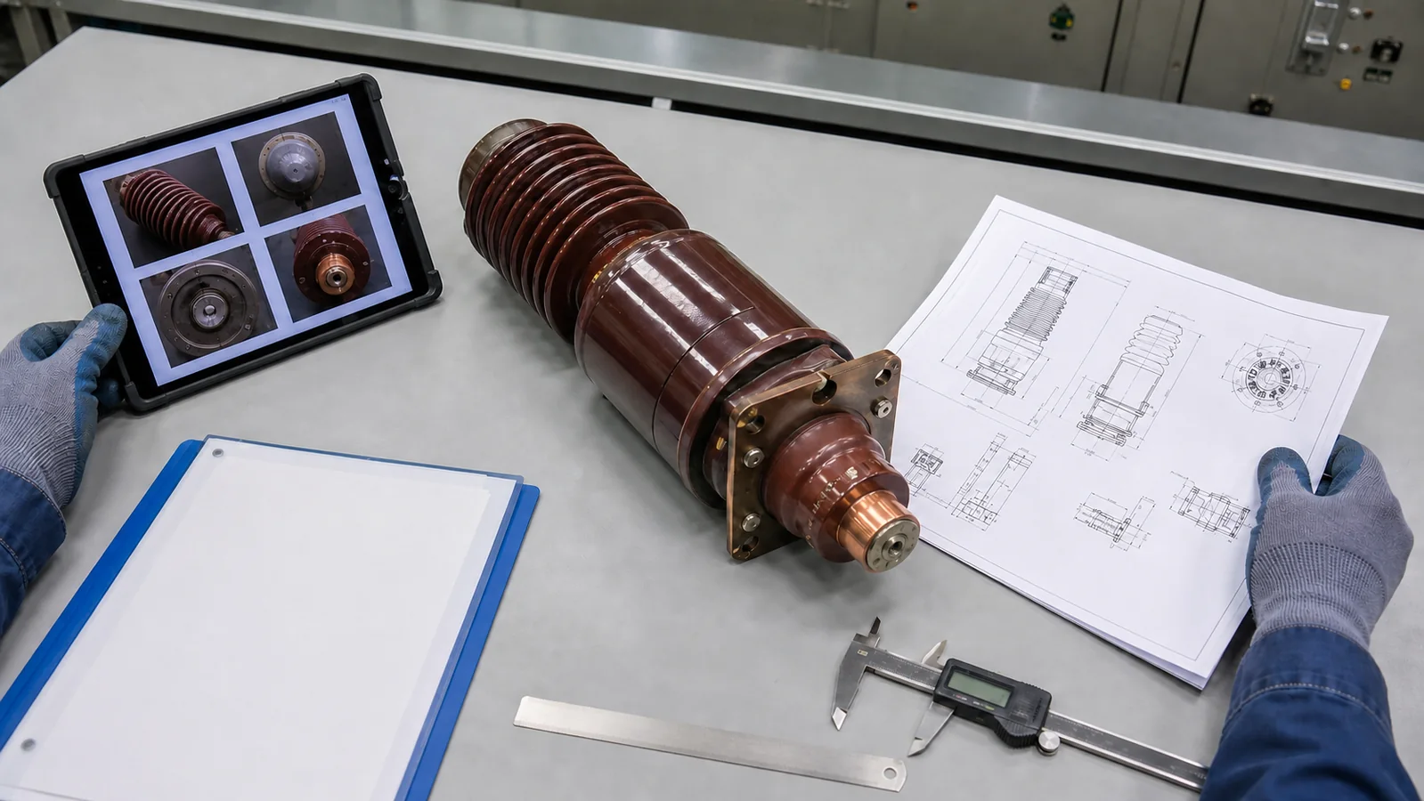
Tools produce observations and measured values; approved documents determine whether those results pass.
| Review activity | Typical tool or method | Acceptance source |
|---|---|---|
| Part identification | Nameplate photographs, equipment register, part markings | Approved bill of materials and breaker records |
| Dimensional comparison | Calibrated caliper, depth gauge, templates where approved | Released pole and frame drawings |
| Primary-path resistance | Suitable micro-ohmmeter and approved connection method | Breaker-specific procedure, baseline, and limit |
| Insulation assessment | Visual examination and approved insulation test equipment | OEM manual and project test procedure |
| Mechanical movement | Gauge or timing analyzer where the approved procedure requires it | Mechanism data, travel/timing method, and acceptance limit |
| Vacuum integrity | Manufacturer-approved method for the interrupter design | Interrupter or breaker service instruction |
| Final release | Drawing review, inspection record, test record, and sign-off | Project specification and quality plan |
Do not apply a test merely because an instrument is available. The test voltage, injected current, connection method, mechanical access, sequence, and pass/fail limit must be suitable for the exact breaker. Unapproved testing can produce misleading results or damage insulation and interrupter components.
A useful RFQ lets the supplier compare the installed part with a controlled technical basis. Include:
Before purchase approval, ask the supplier to identify the proposed part number, construction family, drawing match, exclusions, and any information still assumed. Keep the approved drawing revision with the purchase record. That package is more useful than a request stating only VS1 pole, 12 kV.
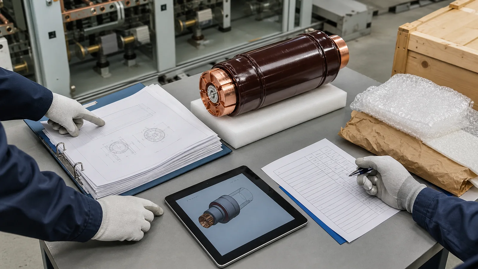
A vacuum pole assembly makes one phase of a VCB electrically connected, insulated, mechanically supported, and operable. The vacuum interrupter is central to that assembly, but it is only one part of the compatibility decision.
For replacement work, start with the exact breaker identity, controlled drawings, old-part photographs, interface dimensions, and approved acceptance sources. Treat matching appearance and nominal ratings as screening clues, not approval evidence. This approach gives engineers, panel builders, and buyers a clear basis for an RFQ and a defensible path to technical approval.
The vacuum interrupter is the sealed switching chamber in which the contacts separate and the arc is extinguished. The pole assembly is the larger phase-specific unit that positions or embeds the interrupter and adds the conductive, insulation, mounting, and drive interfaces needed by the breaker.
Not on the VS1 description alone. Manufacturer, breaker generation, terminal geometry, mounting, insulation body, operating-rod connection, ratings, and controlled drawings must be reviewed before interchangeability is approved.
Send the complete breaker nameplate, old-part photographs, part markings, breaker and pole drawings, key dimensions, cabinet model, ratings, quantity, destination, and required inspection documents. Include the project acceptance requirements when they differ from the manufacturer’s normal supply scope.
No. The standard addresses AC circuit-breaker requirements within its scope. It does not define the proprietary dimensions and internal interfaces of every pole assembly. Fit and function require breaker-specific technical evidence.
Use the breaker-specific maintenance instructions and approved test criteria. Relevant evidence can include visual insulation condition, verified resistance trends, vacuum-integrity assessment, mechanical movement, operation history, and repair limits. Cleaning, adjustment, repair, or replacement should follow the approved procedure rather than appearance alone.



