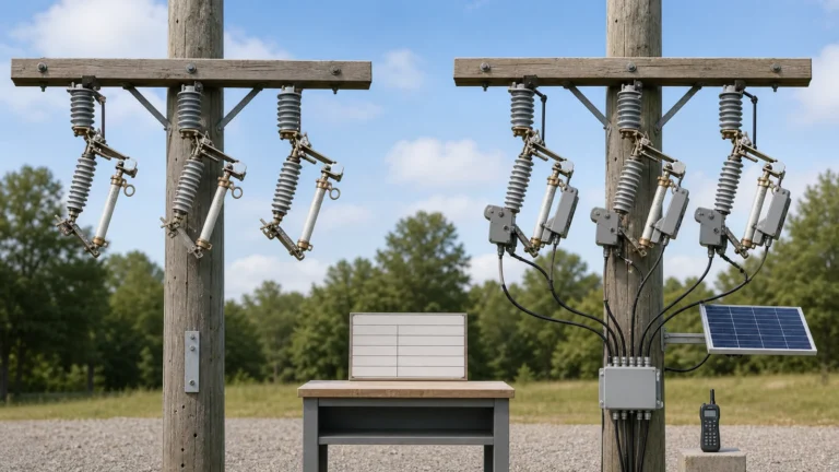
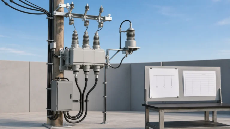
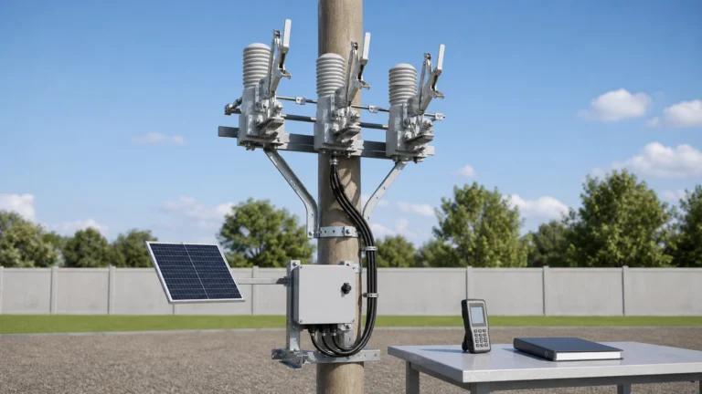
Quotation form
Send an inquiry
Start with the basics. Our team can follow up for missing drawings, standards or packing details.
Submitted details are used only for quotation, technical review and project communication.

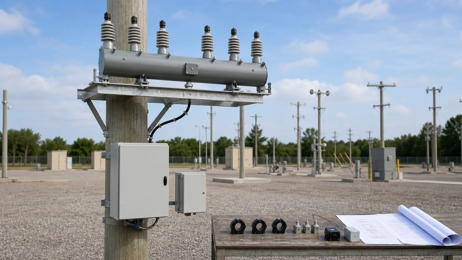
All images are generated illustrative technical visualizations, not XIYA POWER factory, quotation, order, design, selection, installation, inspection, test, commissioning, maintenance, failure, outage, operation, or field photographs.
A pole mounted load break switch automation design starts after the feeder role and load-switching duty are approved. Freeze the switch body first. Then define command authority, permissives, sensing, control power, communication, pole interfaces, records, and lifecycle ownership. A controller adds interfaces; it does not prove fault interruption or automatic reclosing.
Separate three functions before requesting a model. The load break switch body performs its declared load-switching duty. The optional automation package adds motor operation, sensing, records, and communication. The approved upstream protection design handles fault clearing. Automatic restoration exists only when a separately rated protection scheme is assigned that function.
The Smart Grid equipment hub shows adjacent equipment with different primary duties. Do not select by the presence of a controller cabinet alone.
Use this system-design matrix:
| Decision zone | Required input | Design output | Release evidence | Hold condition |
|---|---|---|---|---|
| Feeder role | One-line, normal state, transfer path | Declared topology and switch position | Approved feeder drawing | Normal state is unclear |
| Switching duty | Load, transfer current, fault level, upstream clearing | Selected voltage, current, making, breaking, and short-time duties | Nameplate, study, manufacturer evidence | Duty is incomplete or mixed |
| Authority | Command origins, operators, selector states | Local and remote authority matrix | Approved control narrative | Remote permission is undefined |
| Sensing | Quantities, range, accuracy, failure behavior | Sensor and wiring schedule | Controlled drawings and data | Ratio or failure state is missing |
| Power | Source range, continuous and motor demand | Power and protection schedule | Approved load calculation | Starting demand is unknown |
| Communication | Protocol, points, time, accounts | Interface and point-map package | Conformance and integration evidence | Only a port label is returned |
| Site fit | Pole, clearance, route, environment, access | Mounting and cable package | Approved overlay and drawings | Cabinet or route is not frozen |
| Lifecycle | Inspection, gas, spares, software, records | Maintenance and handover plan | Named owners and controlled files | No lifecycle owner exists |
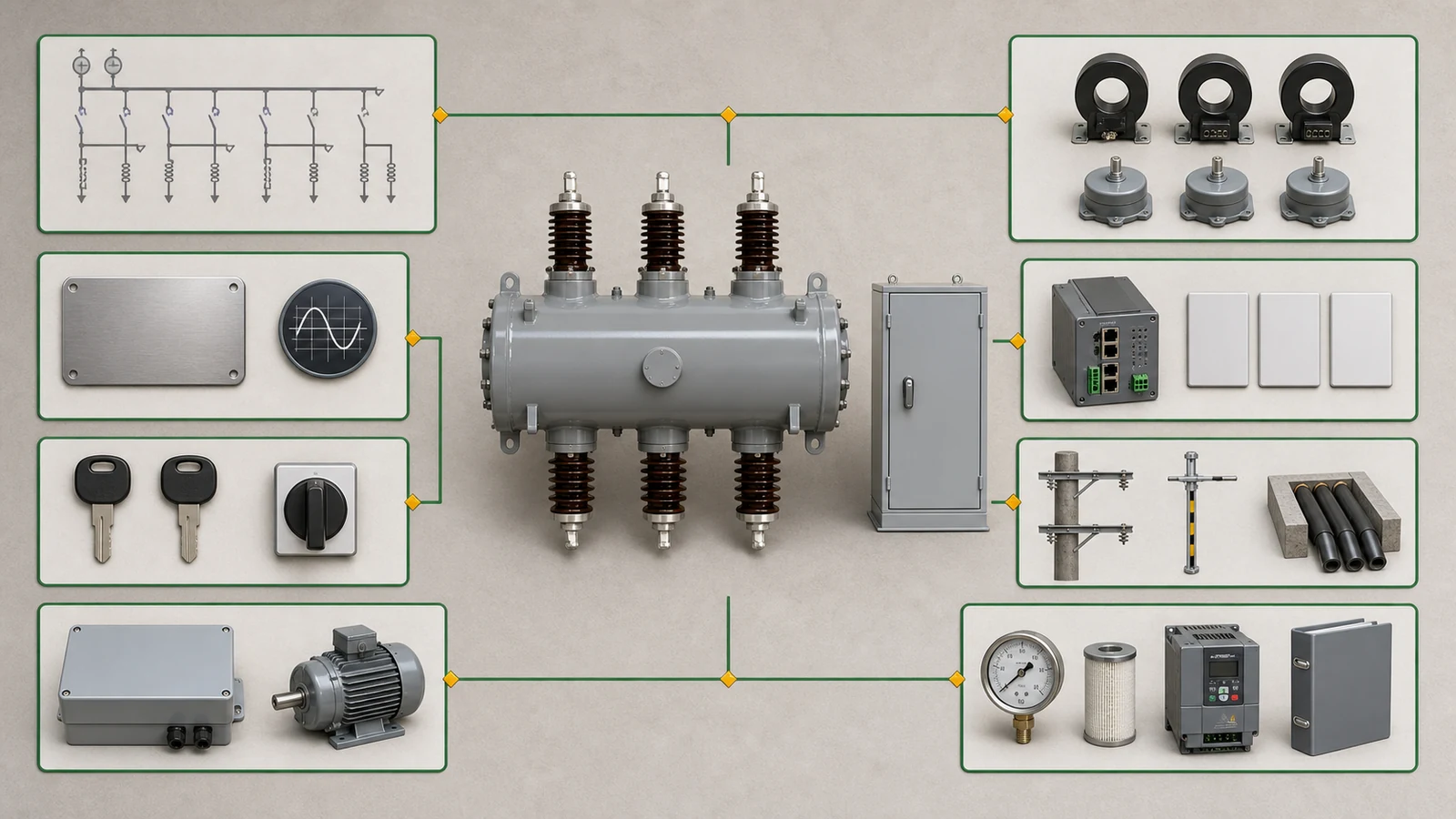
The controller should be the last major package layer to freeze. Otherwise, its sensor inputs, motor cable, supply, cabinet, and SCADA interface can be matched to the wrong switch body or feeder role.
The pole-mounted SF6 load break switch product page separates the LRFW screening layer from an RPS/PGS comparison layer. Keep them separate in every RFQ and compliance table.
| Product data set | Published screening data | Design use |
|---|---|---|
| LRFW | 12/24/36 kV; 400/630 A; 5,000 mechanical operations; 400 full-load operations; IP65; SF6 leak rate <=0.5% per year | Screen the switch body, then confirm the selected series and revision |
| LRFW environment | Altitude <=3,000 m; -40 C to +50 C; wind <=34 m/s; pollution III/IV | Compare with site data without treating the page as approval |
| RPS/PGS comparison | 6-40.5 kV; 400/630/800/1,250 A; 20 kA for 4 s; IP67; suspended or horizontal mounting | Use only when that separate series is offered and controlled |
Do not transfer the RPS/PGS short-time value, IP level, mounting, or separate gas-leakage reference into an LRFW offer. The page also reports different supplier-document standard references. Confirm the selected model, purchaser standard, nameplate, drawings, and test evidence before stating compliance.
The official IEC 62271-103:2021 page covers three-phase AC switches and switch-disconnectors for their switching function. Its public scope includes indoor or outdoor equipment above 1 kV through 52 kV and frequencies through 60 Hz. That scope does not select an LRFW model, confirm its ratings, or approve a controller design.
Freeze rated voltage, current, frequency, making and breaking duties, short-time withstand, service conditions, mounting, gas requirements, and controlled revisions. Use the project specification, short-circuit study, protection study, selected manufacturer data, and controlled drawings as the release evidence chain. Controller sensing, oscillography, or time-current tools do not extend primary switching duty.
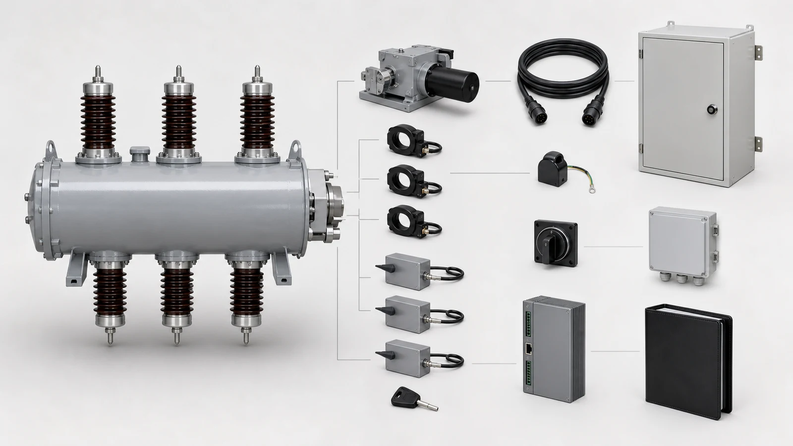
List every command origin: manual mechanism, local controller, engineering tool, SCADA, and any automatic supervisory function. For each origin, define who may open or close, which selector state permits the command, and what happens when commands conflict.
Create an authority matrix with local, remote, maintenance, blocked, and communication-loss states. Define dispatch approval, account permissions, confirmation rules, and the rejection response. A blocked command should return a named reason and create a timestamped event.
Permissives can include declared feeder state, selector position, control voltage, gas status, and external protection or topology inputs. The selected design must identify each source and whether the block is hard-wired or implemented in controller logic. Do not assume a manual-to-motor interlock, override, or fallback sequence from a feature list. Confirm those functions in the selected drawings and operating documents.
A user-boundary breaker may combine interruption, sensing, and controller logic for a different network boundary. Keep that decision in the user boundary switch selection guide. Smart fuse alarms and motorized fuse movement also remain a different package; the smart fuse comparison explains that boundary.
For this load break switch, state explicitly that the upstream protection design clears faults. Remote open or close should execute only the declared switching function. Do not add automatic fault trip, reclose, or restoration language without separately rated equipment and approved logic.
The product page lists phase and ground current sensing, three-phase voltage sensing, and calculated power, energy, power factor, and flow direction. Each channel still needs a selected sensor type, ratio, range, accuracy, burden, polarity, wiring, quality state, and failed-sensor response.
The controller also lists RS-232, Ethernet, and RS-485. These are physical interfaces, not protocol evidence. An RFQ must name the protocol, version, profile, addressing, data types, engineering units, quality flags, command responses, time source, event resolution, retry behavior, and communication-loss state.
Build one command and evidence chain:
| Chain stage | Required definition | Evidence |
|---|---|---|
| Dispatch or SCADA | Authorized account and command intent | Authority record and audit log |
| Gateway and bearer | Route, addressing, security, fallback | Network and interface design |
| Controller | Protocol profile, point map, logic revision | Conformance evidence and configuration |
| Permissive and selector | Required states and block reasons | Control narrative and interlock drawing |
| Motor and switch | Command result and declared position feedback | Wiring and selected mechanism data |
| Records | Timestamp, quality, sequence, retention, export | Event and backup specification |
Separate engineering access from operational access. Front-panel, PC, web, Ethernet, or USB configuration needs named custody, permissions, change records, and an approved configuration baseline. Do not assume that engineering records, oscillography, or time-current tools are available through SCADA unless the returned protocol profile says so.
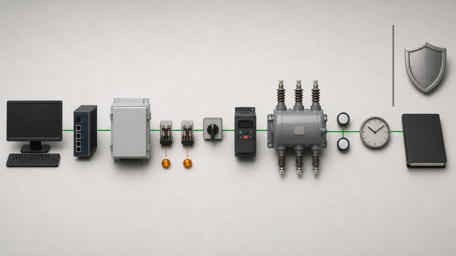
Build a power schedule for the controller, sensors, modem, indicators, heater if used, and motor. Separate continuous, intermittent, peak, and starting demand. Compare the total with the source voltage range, protection, cable drop, storage if used, and degraded behavior. Nominal source voltage alone does not prove compatibility.
Freeze the cabinet position before ordering cables. Use a pole overlay to check the switch envelope, terminal clearances, cabinet access, mounting brackets, connector orientation, grounding, surge protection, and every route length. Confirm environmental limits for both switch and cabinet; do not apply switch-body screening values to the controller automatically.
Use this RFQ checklist:
| Package | Required input | Returned evidence | Hold condition |
|---|---|---|---|
| Switch body | Voltage, current, duty, fault level, clearing time | Series, nameplate, drawings, test evidence | Duty or revision is absent |
| Controller | Functions, logic, selector, interlocks | Manual, control narrative, logic revision | Function remains a feature label |
| Sensing | Quantities, range, accuracy, wiring | Ratios, burden, polarity, failure states | Sensor schedule is incomplete |
| SCADA | Protocol, point map, time, commands, accounts | Profile, point list, conformance evidence | Port is returned without integration data |
| Power | Source range and load schedule | Continuous and motor demand, protection | Peak demand is unverified |
| Pole interface | Overlay, routes, environment, access | Mounting, cable, grounding, surge drawings | Cable or cabinet position is open |
| Lifecycle | Gas, inspection, spares, software, training | Maintenance and handover package | Owner or backup is missing |
The intelligent disconnector commissioning guide provides the adjacent input and handover framework. Adapt it to the selected LBS package rather than copying device-specific settings or procedures.
Representative engineering review, entirely synthetic, illustrative, and non-universal. This is not a XIYA POWER customer, supplier, factory, quotation, order, design, selection, installation, inspection, test, commissioning, maintenance, failure, outage, operation, or field case. No compliance, acceptance, safety, supply, reliability, or result is claimed.
Synthetic project inputs: The system is 22 kV nominal, 24 kV equipment class, and 50 Hz. A normally open loop point carries 315 A normally and may transfer 445 A. Prospective three-phase fault current at the pole is 9.2 kA symmetrical RMS. The synthetic protection study assigns fault clearing to an upstream protective device. It assigns no fault interruption or automatic reclosing to the LBS.
Remote open and close require dispatch authorization and declared permissives. Requested inputs are phase current, ground current, and three-phase voltage. SCADA requires IEC 60870-5-104 over Ethernet, with engineering access separated from operational access. The pole offers a synthetic 110 V AC source with 300 VA continuous capacity.
The site is 1,800 m above sea level, with -25 C to +45 C air temperature, 32 m/s wind, and pollution grade IV. The frozen controller route is 7.2 m.
Synthetic candidate response: The illustrative response identifies an LRFW 24 kV, 630 A body and optional LBS controller. It returns no controlled series revision, approved nameplate, selected standard, or LRFW short-time evidence against 9.2 kA and the upstream clearing duration.
It lists Ethernet, RS-485, and RS-232 without a confirmed IEC 60870-5-104 profile, point list, quality flags, time source, event sequence, or account owner. Sensing functions lack ratios, accuracy, burden, polarity, wiring, and failed-state behavior. Controller demand, motor starting demand, voltage range, and degraded behavior are absent. The returned cable is 6.0 m for the synthetic 7.2 m route.
| Gate | Open decision | Primary missing evidence | State |
|---|---|---|---|
| 1 | Switch body, selected series, duty, standard, gas, drawings | Controlled revision, nameplate, short-time evidence, gas plan | Hold |
| 2 | Authority, selector, permissives, interlocks, upstream protection | Authority matrix, interlock drawing, blocked-command response | Hold |
| 3 | Sensors, protocol, points, time, accounts, records | Sensor schedule, IEC 60870-5-104 profile, point map, time source | Hold |
| 4 | Power, cabinet, cable, grounding, spares, handover | Motor demand, voltage range, corrected cable, lifecycle owners | Hold |
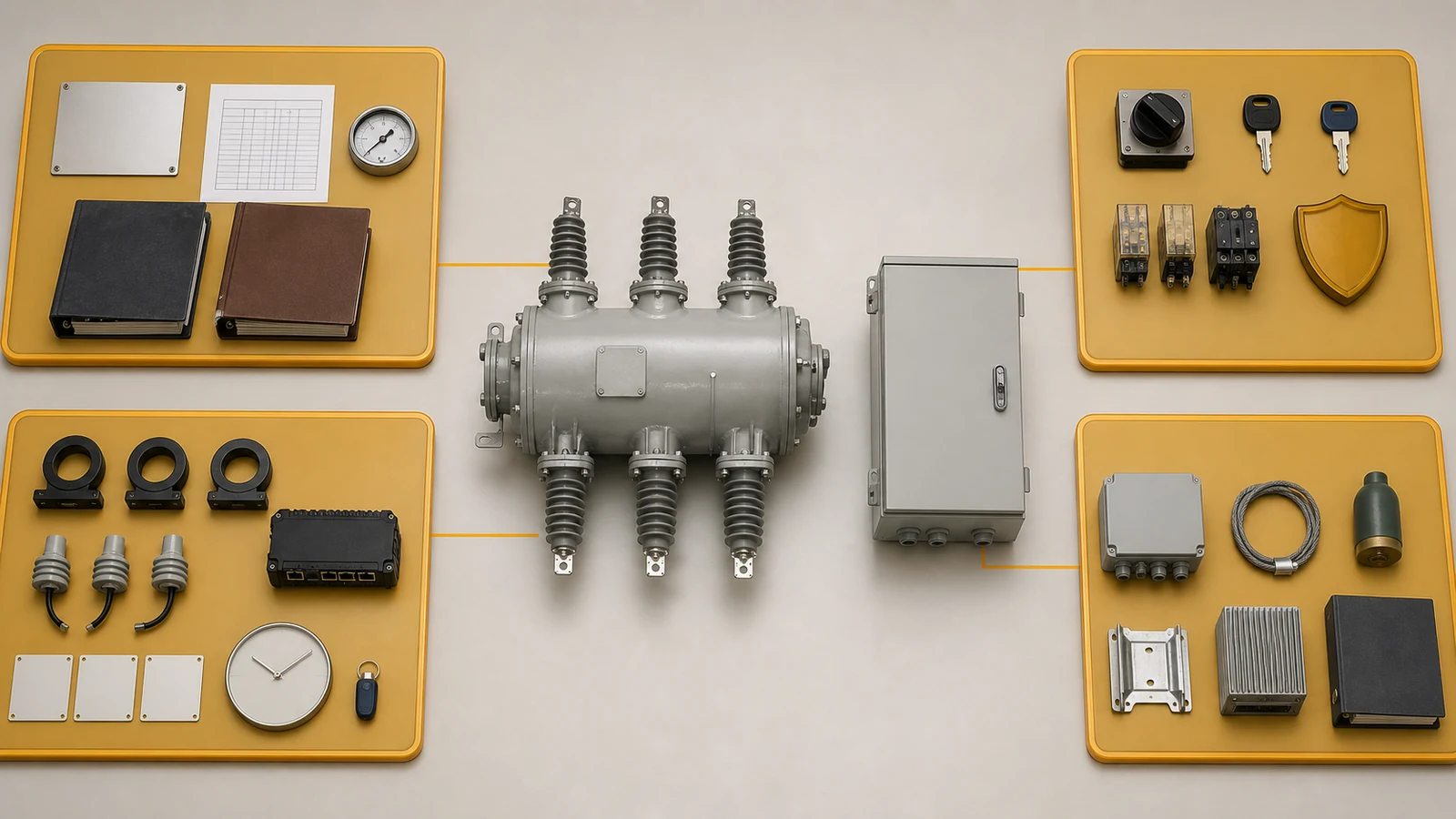
Neither the switch body nor the automation package is selected, accepted, ordered, installed, tested, commissioned, or proven. Close each gate with controlled evidence before release.
It adds motorized operation, sensing, event records, and communication to an already selected load break switch. It does not change the switch body’s declared making, breaking, or short-time duty.
No. A controller adds interfaces and logic around the LBS. Fault interruption and automatic reclosing require separately rated equipment, approved protection logic, and supporting evidence.
Define command authority, selector states, permissives, interlocks, conflict handling, blocked-command responses, position feedback, manual fallback, and the upstream protection boundary.
Request sensor ratios and accuracy, wiring and failure states, protocol profile, point map, commands, quality flags, time source, event resolution, communication fallback, accounts, and configuration records.
Compare continuous and starting demand with the source voltage range, capacity, protection, cable drop, storage if used, and degraded behavior. Confirm the calculation with selected manufacturer data.
Hold it when switch duty, authority, interlocks, sensing, protocol, time, power, pole fit, cable, configuration, spares, documents, or lifecycle ownership remains missing or uncontrolled.