Quotation form
Send an inquiry
Start with the basics. Our team can follow up for missing drawings, standards or packing details.
Submitted details are used only for quotation, technical review and project communication.

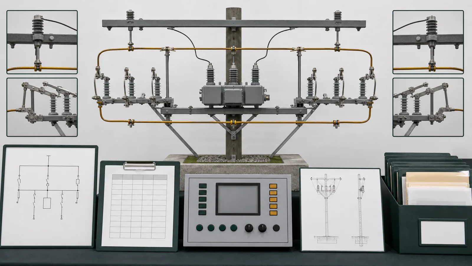
All images are generated illustrative technical visualizations, not XIYA POWER equipment, factory, utility, feeder, pole, recloser, bypass, switching, isolation, earthing, installation, commissioning, maintenance, outage, incident, or field photographs.
By Candy Zhao, Sales Director at XIYA POWER.
Bypass disconnect recloser isolation is not one switching function. A bypass path can maintain feeder continuity around a recloser, while interruption, source/load isolation, protective earthing, controller authority, and permission to work remain separate responsibilities. This guide reviews topology and evidence; it is not a switching order, operating procedure, or universal safety instruction. Actual work requires approved site rules, a project switching order, risk controls, and authorized personnel.
Review the complete arrangement through one selection matrix. Each gate needs a controlled required input, a decision owner, an evidence source, and a hold condition.
| Gate | Required input | Decision | Evidence source | Hold condition |
|---|---|---|---|---|
| Topology and sources | Approved one-line, physical diagram, normal and alternate sources, backfeed/DG, terminals, connection points, work-zone boundary | Which current paths and boundaries exist in each defined state | One-line, system study, project specification | Sources, terminals, or state paths disagree |
| Device role and duty | Recloser, bypass, isolating and earthing functions; voltage, BIL, current and fault inputs | Which exact device performs each declared duty | Short-circuit study, manufacturer data, adopted standard | Duty is assigned by appearance or generic class |
| State and authority | Design states, controller modes, local/remote authority, automatic functions, status, locks, tags, interlocks | Which state evidence and authority basis are required | State and controller-authority schedules | Position, authority, or procedure basis is incomplete |
| Physical interfaces | Structure, phase spacing, mounting, operating side, terminals, jumpers, loads, access, clearances | Whether one offered configuration fits one approved structure | Reconciled drawings and calculations | Geometry or responsibility remains open |
| Release evidence | Ratings, diagrams, schedules, procedure reference, inspection plan, configuration evidence, deviations | Whether technical release has a complete data pack | Approved register and release record | Any prior gate remains open |
The bypass disconnector application page owns the product-family and project-layout inputs. The Distribution Switching Equipment pillar separates bypass duty from interruption, visible isolation, fuse protection, earthing, and other switching roles.
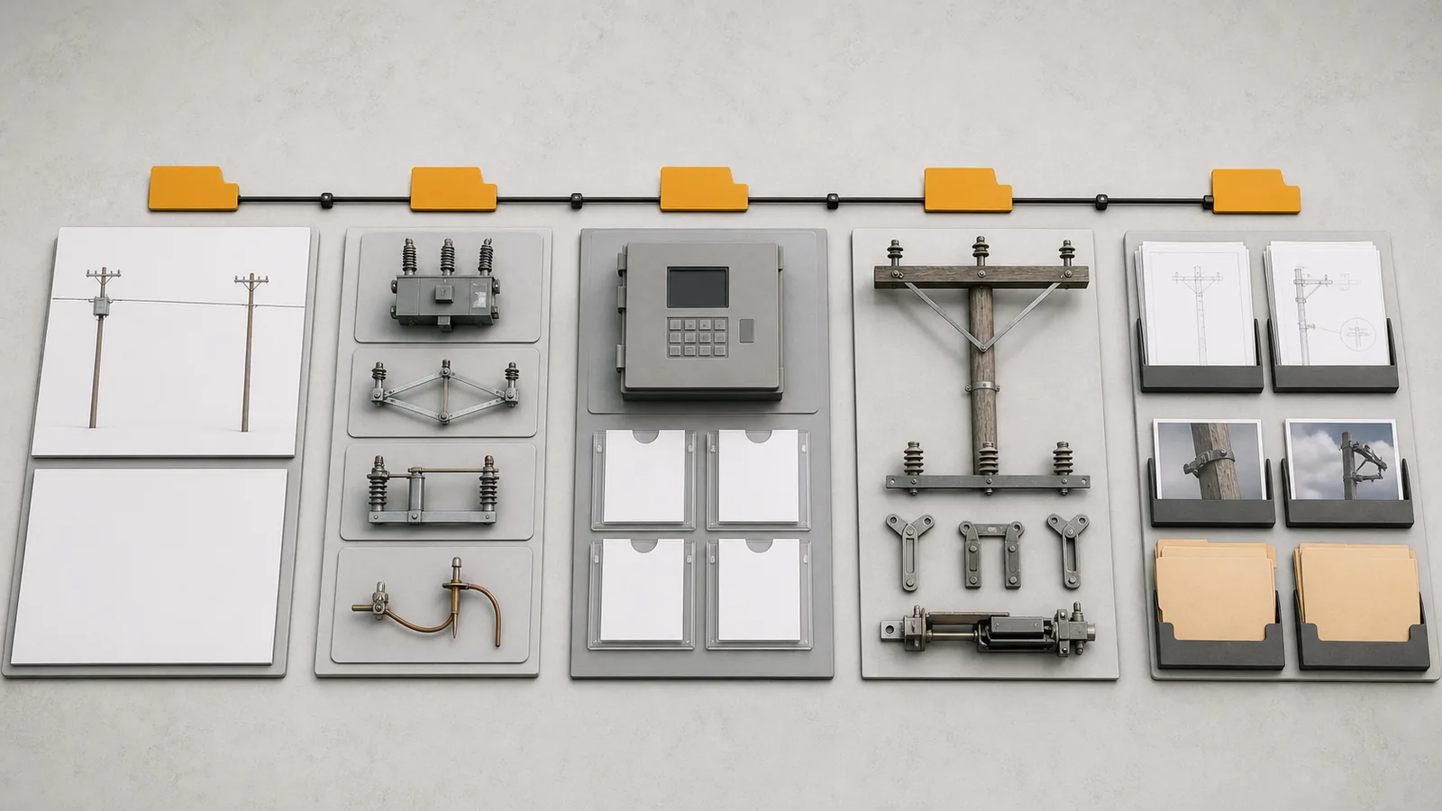
Illustrative technical visualization: exactly five application-review gates remain amber and independent, with no approved topology or release state.
Start by assigning functions, not product names.
| Function | Design role | Boundary to preserve |
|---|---|---|
| Recloser | Interrupts fault current and applies the approved protection/reclosing behavior | It is the device being bypassed, not the bypass current path or the work-zone isolator |
| Bypass path | Provides an alternate path around the recloser for a defined system state | It may remain energized; continuity does not prove isolation or absence of voltage |
| Source/load isolation points | Define the project work-zone boundary when established under the approved procedure | A disconnector cannot be assumed to interrupt load unless the exact device and adopted procedure permit that duty |
| Earthing arrangement | Provides the separately designed grounding function after the required isolation basis is established | Bypass position is not protective earthing |
The official public page for IEC 62271-102:2018 covers relevant AC disconnectors and earthing switches above 1,000 V and up to 60 Hz. Its public summary discusses isolating distance, interlocking, position indication, operating force, service-temperature testing, and certain switching-capability classifications. It does not select this topology, prove a device can interrupt project load, authorize work, define a switching order, establish absence of voltage, or provide project-specific earthing and clearance rules.
A recloser terminal can remain at system potential while a parallel bypass carries current, depending on the topology and isolating-device states. The review must therefore map every possible energization source and the exact work-zone boundaries on controlled drawings. Detailed earthing-switch duty and sequence inputs remain with the earthing-switch selection guide.
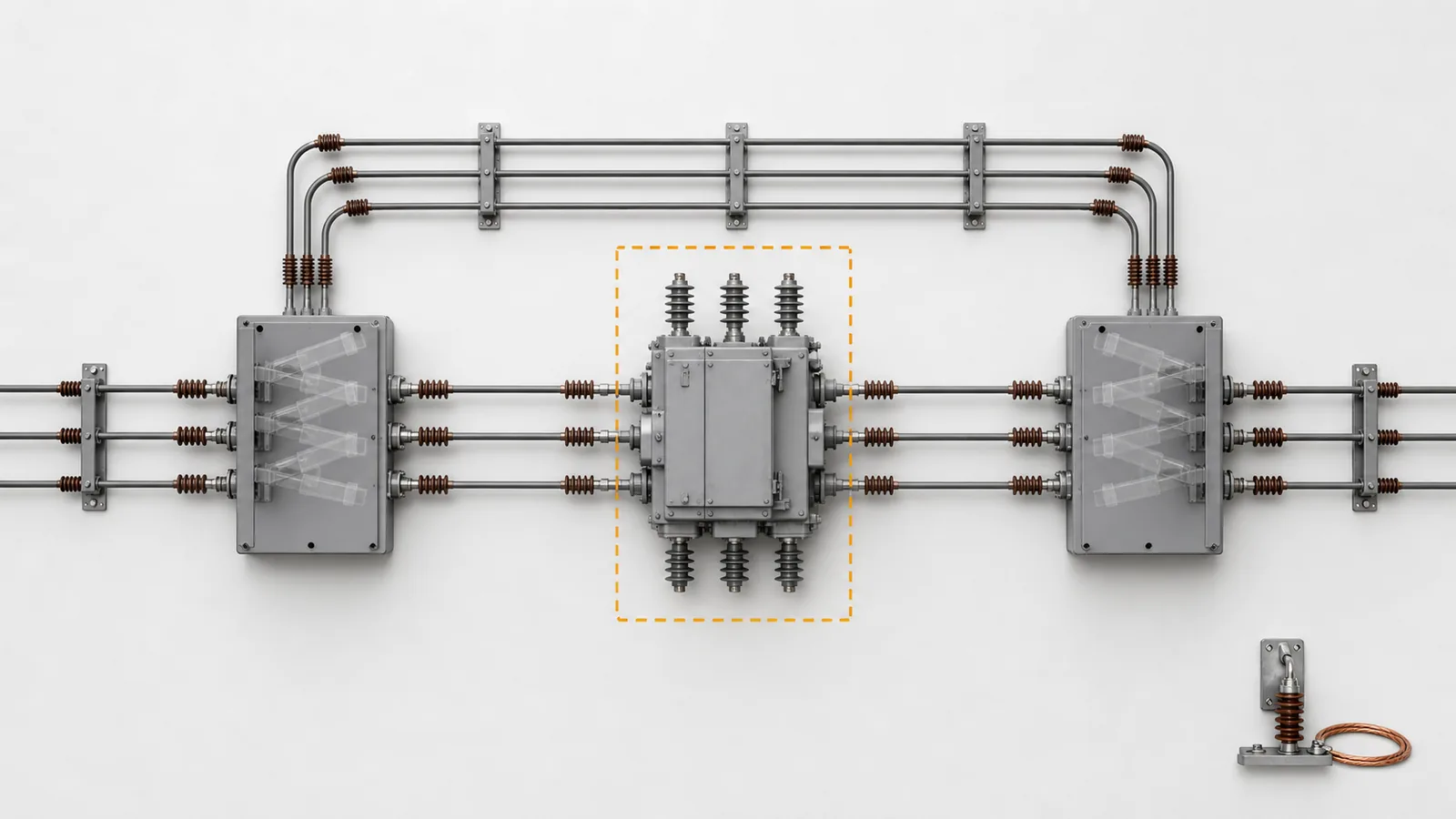
Illustrative technical visualization: a wordless feeder topology separates recloser, parallel bypass, source/load isolating points, and the bounded work-zone review without action-order arrows. No device position, isolated state, earthed state, or permission-to-work condition is represented.
A design-state table documents intended current paths and proof requirements. It must not become a list telling an operator what to actuate or in which order.
| Design state | Intended current-path concept | Required evidence | Authority and work-zone boundary | Hold condition |
|---|---|---|---|---|
| Normal service | Feeder function through the recloser; bypass unavailable for current in the stated normal design | Controlled device-position table and controller status basis | Normal local/remote and automatic-function authority defined | The normal reference state is ambiguous |
| Bypass service | Feeder continuity through the declared bypass path; recloser excluded from the load-current path | Bypass duty, recloser terminal-potential review, and position/status evidence | Controller and remote-command treatment for this design state defined | Energized points or command authority are unknown |
| Isolated work-zone design state | Project-defined isolation boundary around the recloser, with all possible sources addressed | Isolation-point evidence, absence-of-voltage and earthing procedure references, locks/tags and status requirements | Approved site procedure and authorized-person roles control implementation | Boundary, source control, procedure, or earthing basis is incomplete |
| Restoration-ready design state | Configuration is documented for the approved restoration process | State confirmation, deviation status, temporary-control disposition, and procedure reference | Authority restoration remains governed by the approved procedure | Readiness evidence or authority is unclear |
These are design-review outcomes, not permission to work. A table cannot replace field verification, an approved switching order, the site safety process, or the responsible person’s decision.
The electrical chain begins with system voltage, adopted insulation basis, maximum expected maintenance-through-load, fault current at the installation point, peak/momentary and short-time requirements, declared switching capability, and service conditions. Map each input to the exact bypass blades, isolating devices, jumpers, terminals, and structure. Never compare an rms study value directly with a peak rating without the approved basis, and do not treat a current rating as evidence of switching capability.
The state schedule also needs controller mode, local/remote command authority, automatic reclose and remote close treatment, SCADA status, prohibited states, indication, locks, tags, interlocks, and auxiliary-contact allocation. The disconnect-switch operating mechanism guide owns manual/motorized drive, linkage, operating side, indication and contact interfaces; this article only defines what the topology/state package must prove.
Physical release requires phase spacing, structure and crossarm, mounting direction, blade and jaw orientation, conductor/jumper geometry, mechanical loads, operating access, clearances, and the responsible interfaces to agree on one drawing set. Photos can support orientation review but cannot prove ratings, clearances, configuration identity, or structural adequacy.
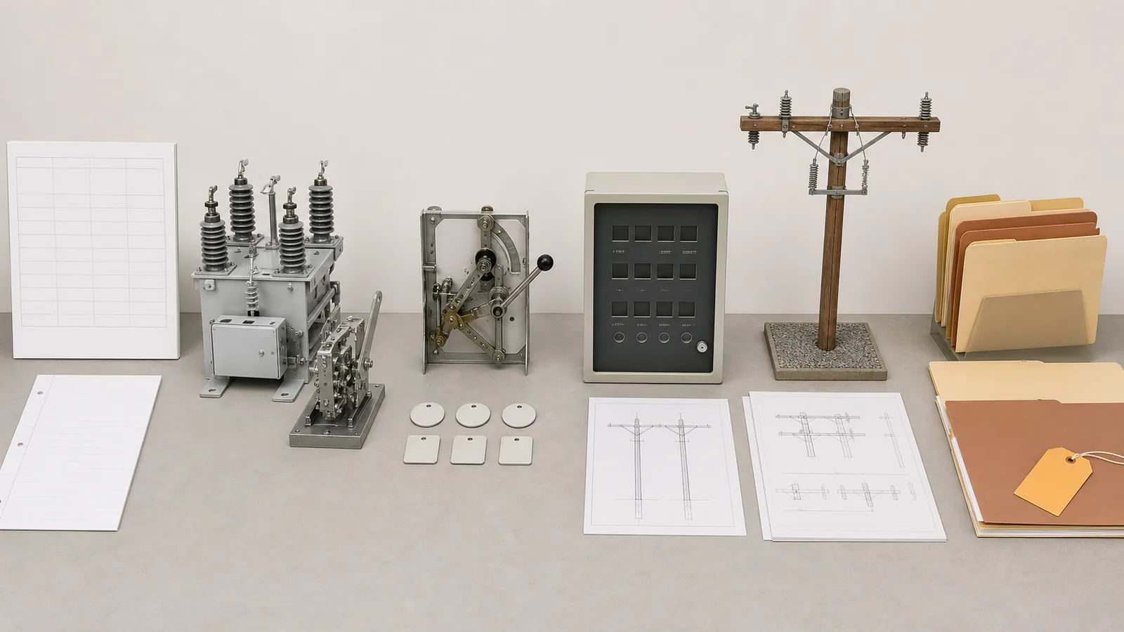
Illustrative technical visualization: one evidence chain connects system study, device duty, mechanisms/status, controller authority, structure drawings, and release records without a logic diagram or pass state.
Use this RFQ checklist to keep supplier returns comparable and prevent a drawing from becoming a substitute for system or safety inputs.
| Required input | Supplier return | Decision owner | Release evidence | Hold condition |
|---|---|---|---|---|
| Approved one-line, sources, terminal identities, state paths | Physical arrangement and device map | System/design engineer | Reconciled one-line and arrangement | Topology differs |
| Voltage, BIL and adopted insulation basis | Exact configuration ratings | Design engineer | Project specification and manufacturer data | Basis is unstated |
| Load current and duration basis | Continuous-current and derating statement | System/design engineer | Load basis and configuration data | Duty mapping is absent |
| Short-circuit study with rms and peak inputs | Momentary/peak and short-time ratings | System/protection engineer | Approved study-to-rating comparison | Quantities or duration are mixed |
| Required switching capability, if any | Exact declared capability and scope | Design/safety authority | Adopted standard and procedure boundary | Load interruption is assumed |
| Controller and state requirements | Interface, indication and contact schedules | Protection/SCADA and operations | State and authority schedules | Automatic/remote authority is unresolved |
| Structure and service conditions | Drawings, loads, environmental statement | Structural/design engineer | Reconciled drawings and calculations | Fit or environment is open |
| Site-procedure reference and test expectations | Procedure-boundary acknowledgment and inspection plan | Safety/quality authority | Approved reference, evidence and deviation register | Procedure or configuration evidence is absent |
Technical release should retain the controlled one-line, state table, rating comparison, mechanism/status schedule, controller-authority schedule, structure drawings, inspection/test records, configuration-applicable evidence, deviations, and named release authority. Send project-specific inputs through the XIYA POWER contact page; a commercial return is not an operating authorization.
Invented representative engineering review for method demonstration only. It is not a XIYA POWER customer, utility, supplier, quotation, order, design, switching order, safety procedure, factory, test, installation, commissioning, maintenance, outage, incident, or field case. Every topology, rating, dimension, state, and returned detail below is fictional and non-universal.
The invented input is one radial 27 kV-class feeder with a pole-mounted vacuum recloser and three-pull bypass/disconnect arrangement. Fictional inputs are a 420 A maximum maintenance-through-load and 12.5 kA symmetrical rms at the location. A candidate return states 27 kV, 630 A continuous current, 125 kV BIL, and 40 kA peak/momentary duty; none is accepted or declared compatible. The structure drawing uses fictional 900 mm phase centers, while the supplier arrangement shows fictional 760 mm phase centers. Normal controller inputs include automatic reclose and remote close; the maintenance basis requests local authority and positive control of unintended automatic/remote operation, without supplying logic or a switching sequence.
| Open hold | Invented gap | Evidence required before decision |
|---|---|---|
| Topology and sources | Terminals, bypass points, alternate/backfeed sources, state current paths, and work-zone boundary do not share one approved diagram | Reconciled one-line and physical arrangement |
| Duty | 420 A, 630 A, 12.5 kA rms, 40 kA peak/momentary, 125 kV BIL, duration, switching capability and service conditions are not mapped to one adopted basis | Study, specification and configuration-specific manufacturer data |
| State, control and isolation | Four design states lack one position table; controller authority, automatic/remote functions, indications, locks/tags, interlocks, contacts and site-procedure reference are incomplete | Approved state, authority and interface schedules plus procedure reference |
| Physical and evidence | 900/760 mm phase centers, structure, crossarm, operating side, jumpers, loads, access, clearances, drawings, inspection plan, evidence and deviations are unresolved | Reconciled drawings, calculations, test/inspection evidence and release record |
All four holds remain open. No topology, state, rating, isolation basis, earthing basis, procedure, configuration, or technical release is selected, safe, approved, compliant, confirmed, successful, or field proven. Missing evidence records an open decision; it does not prove product failure or unsafe work.
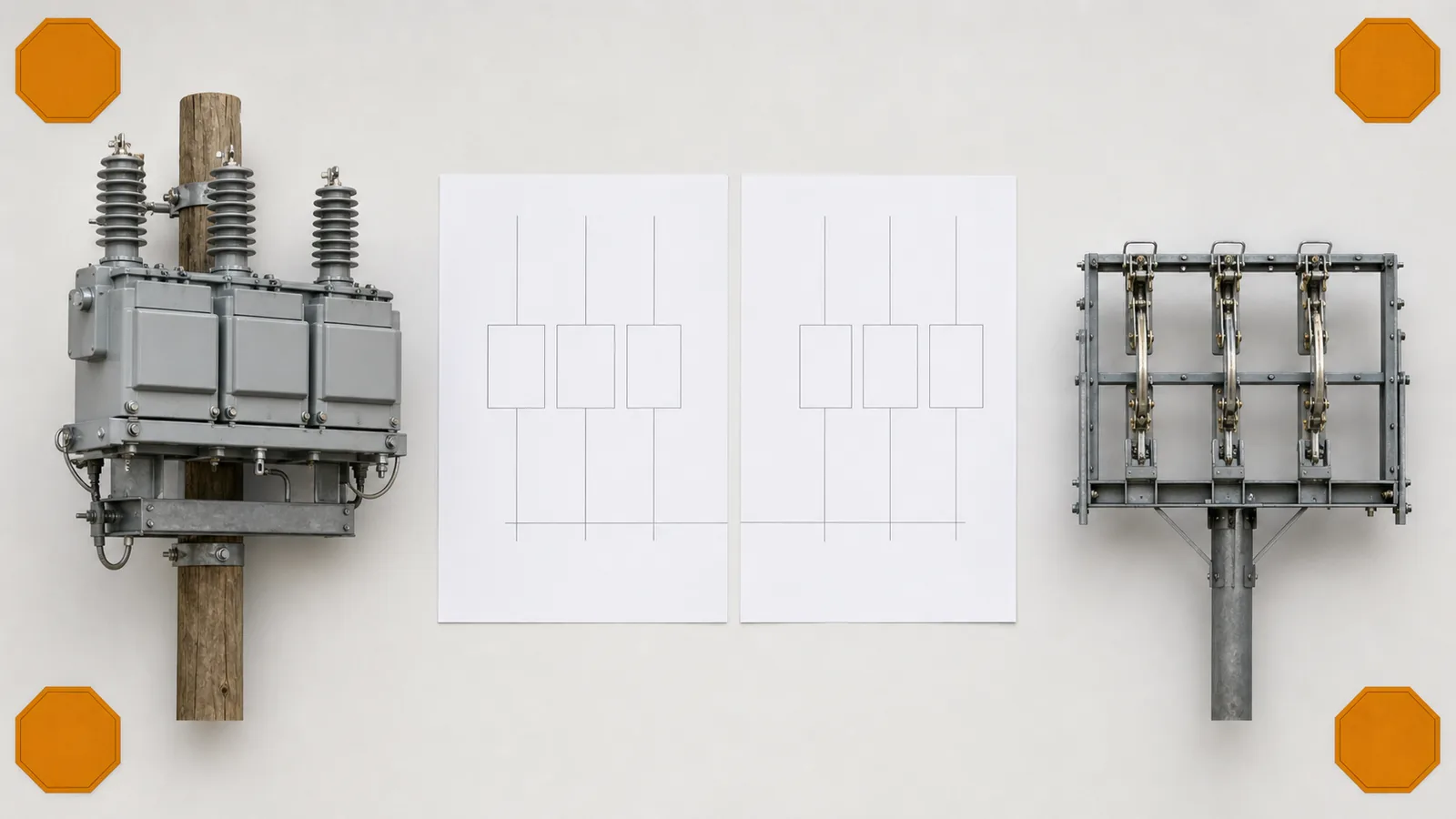
Illustrative technical visualization: an invented 27 kV-class recloser and three-pull bypass review has exactly four amber holds, with no isolated, earthed, accepted or released state.
It provides a controlled alternate current path around the recloser for a defined design state. It does not perform the recloser’s fault-interrupting function, independently isolate the recloser, prove absence of voltage, or provide protective earthing. Those roles need separate devices, evidence and approved procedures.
Closing a bypass does not establish isolation, prove absence of voltage, grant permission to work, or provide protective earthing. A bypass path can remain energized and may leave recloser terminals at system potential depending on the topology. A work-zone boundary requires every source and isolating point to be addressed under the approved site process, with verification and earthing governed by authorized personnel and project procedures.
Only if the exact offered device has a declared capability applicable to the required duty and the adopted standard and approved procedure permit that use. A generic disconnector label, continuous-current rating, or product photo does not prove load-interrupting capability.
Review normal service, bypass service, an isolated work-zone design state, and restoration-ready state. For each, document intended current path, potential sources, required position/status evidence, controller and remote authority, work-zone boundary evidence, procedure reference and hold condition. Do not turn the table into an operating sequence.
Define the required controller mode, local/remote authority, automatic reclose and remote close treatment, SCADA status, indications, interlocks and auxiliary contacts for each design state. The approved site procedure and authorized roles govern the actual blocking, transfer and restoration method; this guide does not supply control logic.
Retain a reconciled one-line and physical diagram, studies and ratings, design-state and authority schedules, manufacturer data, mechanism and contact interfaces, structure drawings, site-procedure reference, inspection/test plan, configuration-applicable evidence, deviations and named technical release. Any unresolved topology, duty, authority, physical or evidence gate keeps release on hold.