Quotation form
Send an inquiry
Start with the basics. Our team can follow up for missing drawings, standards or packing details.
Submitted details are used only for quotation, technical review and project communication.

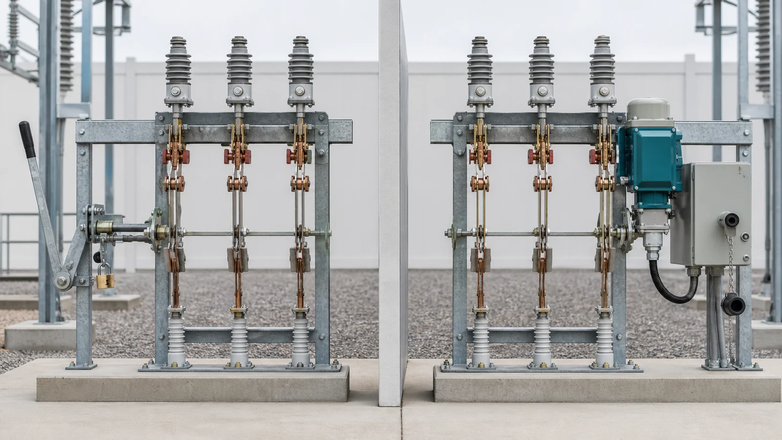
A disconnect switch operating mechanism should be selected as a complete command-to-blade and blade-to-status package. A manual drive can be the correct local solution. A motorized drive can support remote operation only when its supply, controls, authority, linkage, position indication, auxiliary contacts, interlocks, service conditions, and evidence are engineered together.
Do not approve an offer from the words manual or motorized. Freeze the operating objective and interfaces first, then verify the exact switch-mechanism-linkage configuration.
The Distribution Switching Equipment pillar treats the switch body, mechanism, mounting, and interlock package as one procurement decision. The earlier air-break-switch versus disconnect-switch guide owns the duty boundary; use this article after the correct device family is established.
| Decision layer | Required input | Manual-package implication | Motorized-package implication | Release evidence | Hold condition |
|---|---|---|---|---|---|
| Command and authority | Local/remote operating philosophy | Accessible handle, locks and operator authority | Local controls, remote interface and selector/authority logic | Approved command matrix | Authority is undefined |
| Switch arrangement | Geometry, phase drive and mounting side | Shaft, rod, supports and travel must match | Same mechanical chain plus actuator output fit | Configuration drawing | Offered linkage is generic |
| Energy | Human input and access basis | Operating force/torque and reach basis | Motor/control/heater sources, cable route and energy budget | Supply and load schedule | Terminal conditions are unchecked |
| Manual path | Operating and maintenance philosophy | Inherent path, with stops and locking | Declared backup or maintenance method where required | Transfer/blocking description | Simultaneous operation is possible |
| Interlocks | Prohibited states and boundaries | Mechanical, key or padlock interfaces | Mechanical/key plus electrical permissive interfaces | Interface schedule | Logic owner is missing |
| Position and status | Local proof and remote points | Coupled indicator and contact needs | Travel limits, position proof and contact allocation | State/contact schedule | Signals are treated as equivalent |
| Environment and access | Site conditions and working envelope | Outdoor linkage and operator access | Enclosure, condensation control and local access | Service-condition declaration | Offer covers another condition |
| Inspection and maintenance | Adjustment, isolation and spares basis | Linkage access and as-set records | Same plus actuator/control maintenance | Applicable instructions and tests | Evidence covers another variant |
These columns describe selection tendencies, not universal requirements. The project specification and the exact offered design determine which elements are mandatory.
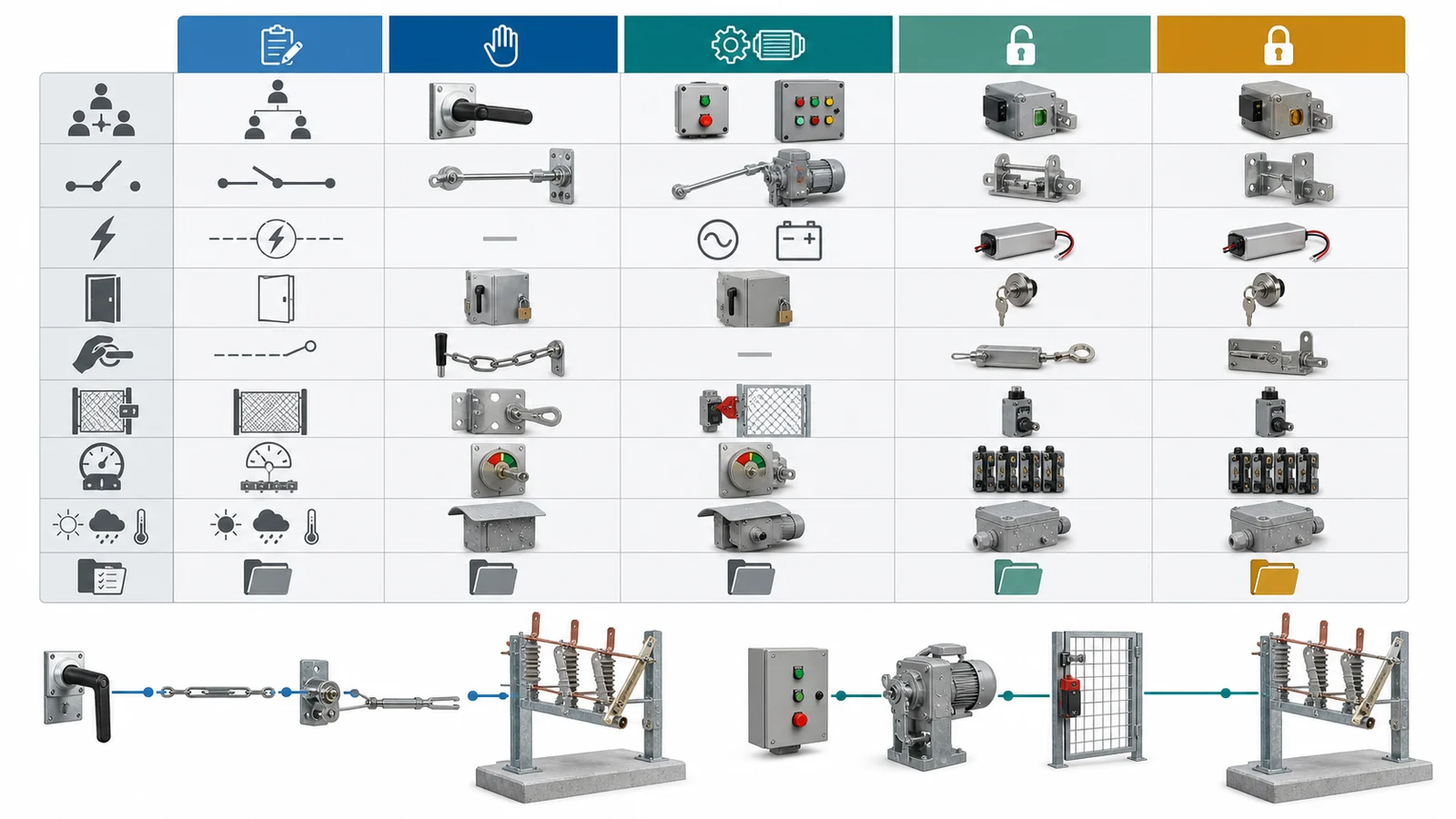
A complete manual path can include a handle or lever, locking/key provisions, shaft or rod, supports and bearings, couplings, adjustable linkage, open/closed stops, the switch interface, and local position indication. Review the operating side and height, human access, declared force or torque basis, travel, locking state, and any need to operate from ground level or outside a restricted zone.
A complete motorized path adds a motor or actuator, gearing, local controls, remote-command terminals, protective or torque-limiting functions where offered, travel devices, terminal blocks, an enclosure, and declared auxiliary loads. It also needs a controlled local/remote authority arrangement and a manual maintenance or emergency method when the project requires one. The method must state how motor energization is prevented during manual engagement.
The live Disconnect Switches owner shows why the mechanism belongs to the switch, mounting, and drawing package. A motor nameplate alone does not prove remote readiness, available terminal voltage, SCADA compatibility, permissive logic, blade position, or linkage fit.
| Comparison point | Manual package | Motorized package |
|---|---|---|
| Normal command | Local human input | Local electrical and/or remote command |
| Energy review | Human input, access and operating basis | Source, cable, starting/running demand and auxiliary loads |
| Mechanical path | Handle-to-linkage-to-blade | Actuator-to-linkage-to-blade, plus declared manual path |
| Authority control | Locks, keys and operating procedure | Local/remote selector, permissions and blocking |
| Position/status | Local indication; contacts if required | Travel control, position indication and allocated status points |
| Main advantage | Low-complexity local operation | Remote or automated command when complete interfaces close |
| Main risk | Poor access or unsuitable operating effort | Incomplete power, control, status or manual-transfer scope |
Neither architecture is universally safer, simpler, faster, or lower cost. Select it against the operating role and complete return package.
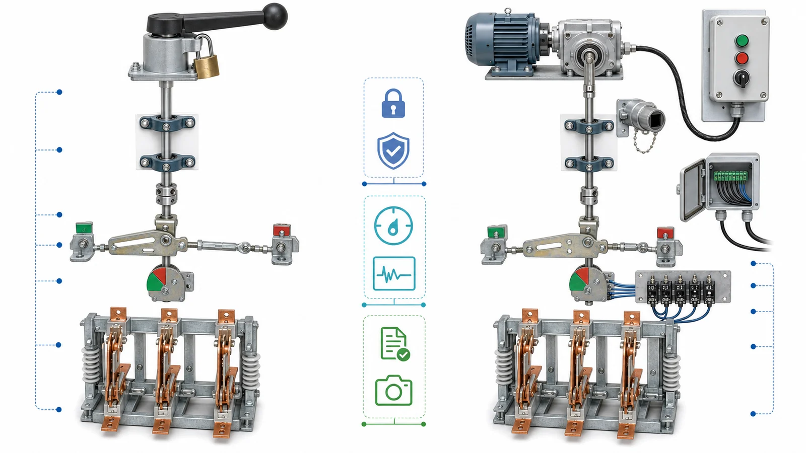
Break geometry sets the mechanism boundary. The earlier center-, double-, and vertical-break comparison owns physical layout; here, its approved geometry becomes an input to mechanism output direction, travel, shaft position, linkage, and working envelope. Independent-pole versus gang operation remains a separate DSE-09 decision.
Review the chain from the mechanism mounting face to the primary contact system:
Do not copy a travel, torque, operating time, pole synchronism, temperature, wind, ice or endurance value from another mechanism. Require configuration-specific open/closed drawings, linkage assembly and bill of materials, adjustment instructions, and travel/operation evidence. The technical release should identify the exact switch model, mechanism variant, geometry, phase-drive arrangement and accessories covered by that evidence.
The public page for IEC 62271-102:2018 covers indoor and outdoor AC disconnectors and earthing switches above 1,000 V and up to 60 Hz. Its public change summary includes interlocking-device withstand/testing, position indication/signalling, operating force, and temperature-test topics. That scope does not provide this project’s mechanism, voltage, contact count, change points or interlock logic.
Keep the state chain explicit:
| State/evidence layer | What it establishes | What it does not establish |
|---|---|---|
| Command permission | An operate command is permitted at that boundary | The command completed |
| Mechanism travel control | The drive reached a control or end-travel condition | The primary contact reached its required state |
| Primary position basis | The blade/contact system reached a mechanically referenced state | Every remote circuit received the state |
| Local indication | An operator can see a declared switch state | The remote indication circuit is healthy |
| Auxiliary contact | A declared contact changed for an allocated circuit | Its change point equals every other position device |
| Remote status/alarm | The control system received and interpreted a signal | The complete mechanical chain is correct without reconciliation |
One device may perform more than one role in an offered architecture, but equivalence must be demonstrated rather than assumed. The contact schedule should identify each NO, NC or changeover contact; its source mechanism; state represented; declared change-point basis; destination; normal/de-energized convention; and used or spare allocation.
Define each mechanical, electrical or key interlock by its prohibited state, input/output boundary, authority, behavior after supply or signal loss, and applicable evidence. DSE-10 owns the detailed earthing-switch duty and sequence; Phase 2 owns terminal-by-terminal control-schematic and detailed logic review.

RFQ checklist and approval data pack — required project inputs:
Per-offer return package:
Keep manufacturer data, the project specification, and the short-circuit study as distinct evidence sources. The short-circuit study supports the switch duty and withstand basis; it does not by itself select motor/control architecture or auxiliary contacts.

Representative engineering review, not a XIYA POWER customer, utility, factory, field, FAT, commissioning, maintenance, outage, or service case. All values are illustrative and non-universal.
Consider an illustrative 72.5 kV outdoor line-bay disconnector. The project lists a 110 V DC station supply, an approximately 60 m control-cable route, remote open/close commands, a local/remote selector, a manual backup requirement, an earthing-switch permissive interface, and eight normally open plus eight normally closed auxiliary contacts.
Remote operation conditionally favors a motorized package, but those inputs do not prove fit. Hold technical release until the offer closes:
The decision is therefore motorized package conditionally selected; technical release held. A different command philosophy, supply, linkage, contact allocation or service condition can produce a different result. Send the controlled drawings and interface schedules through the technical RFQ channel for configuration review.
Use motorization when the approved operating philosophy requires remote or automated command, or when local access and operating requirements make a manual-only path unsuitable. Confirm supply, cable route, authority, linkage, status, interlocks, service conditions and evidence before approval.
It depends on the project and offered design. Where a manual maintenance or emergency path is required, specify its access, engagement method, authority, locks and a blocking arrangement that prevents unintended motor operation while it is engaged.
Not automatically. A motor travel device may represent drive position, while the project may require position evidence mechanically referenced to the primary blade/contact system. Reconcile the sensing point, change basis and evidence for each local and remote state.
Use a project contact-allocation table, not a generic count. Identify each contact’s form, source, represented state, change-point basis, destination, normal convention and spare status, then verify the exact offered auxiliary switch.
Specify the prohibited state and interface boundary for each mechanical, electrical or key interlock, including authority and behavior after signal or supply loss. The mechanism article defines interfaces; the approved operating sequence and detailed schematic define the final logic.
Require configuration-specific mechanism/linkage drawings, motor and supply data where applicable, terminal/control documents, contact schedule, position basis, interlock narrative, manual-transfer details, instructions, applicable tests, adjustment records and deviations. Generic brochures or evidence for another variant are insufficient.



