Quotation form
Send an inquiry
Start with the basics. Our team can follow up for missing drawings, standards or packing details.
Submitted details are used only for quotation, technical review and project communication.

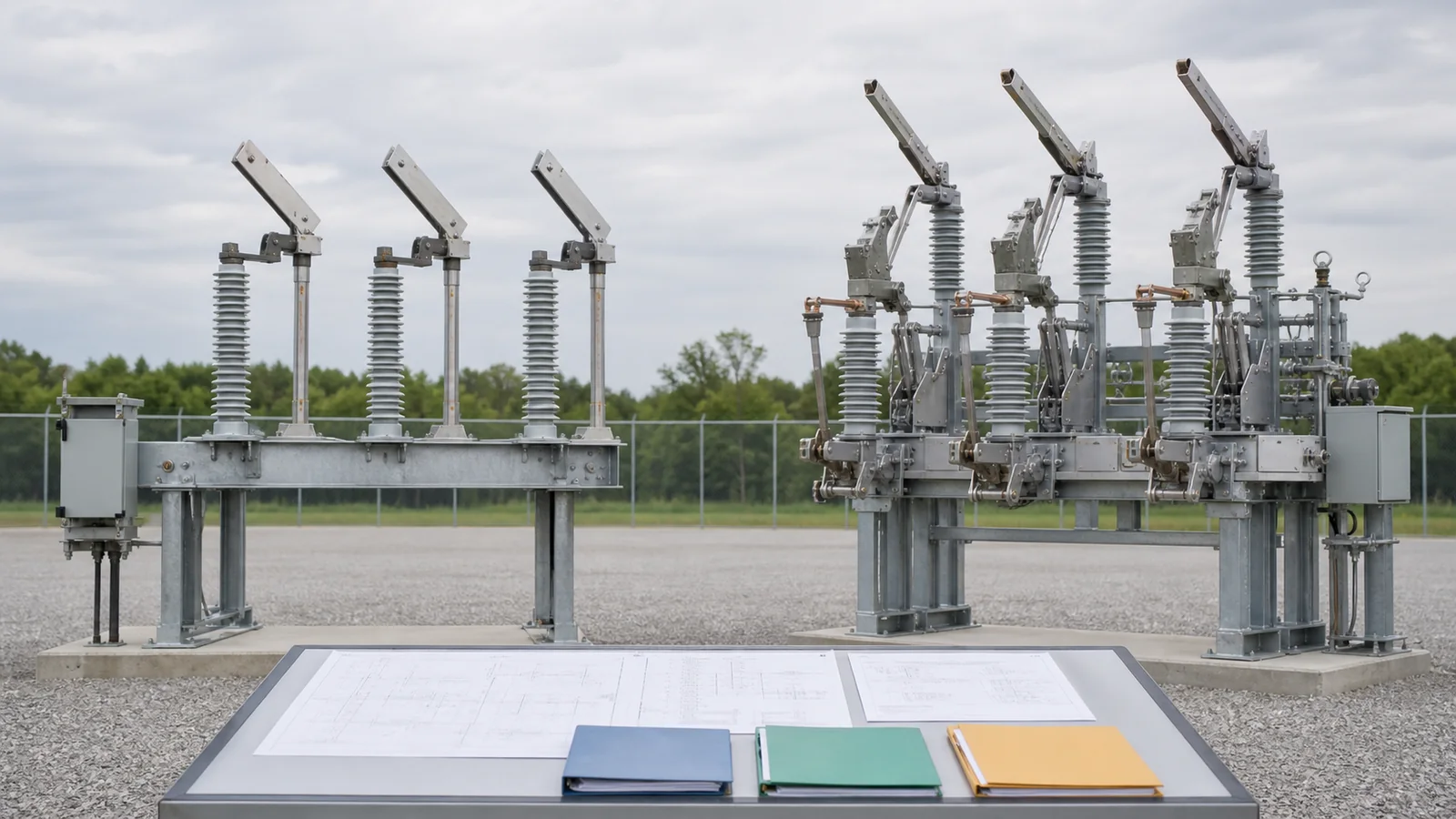
Air break describes construction or switching medium: the current path opens in air. Disconnect switch or disconnector describes an isolation function. Many outdoor air switches perform disconnecting duty, so the terms overlap, but neither name establishes what current the device may interrupt. An outdoor device may break load or another specified current only when its declared making/breaking ratings, applicable product standard, and test evidence cover that duty. Visible blades, arcing hardware, quick-break mechanisms, and motor operators are design features, not standalone proof of load-breaking capability. Start with the required system duty, then compare evidence and the appropriate outdoor air break switch configuration.
Catalog terminology varies by supplier and region. Separate what a label tells you from the evidence still needed for technical release.
| Question | Air-break wording tells you | Disconnect wording tells you | Evidence still required |
|---|---|---|---|
| Switching medium | The current path opens in air | Not defined by the word | Construction drawing and applicable standard |
| Isolation function | Not established by medium alone | Isolation is the primary function | Isolating distance and position-indication evidence |
| Normal-current carrying | Not stated | Device carries its declared current when closed | Rated current and temperature-rise basis |
| Making/withstand duty | Not stated | Only duties declared for the device | Ratings and applicable test evidence |
| Current breaking | Not stated | May include only specifically declared limited duties | Exact breaking rating, class/category, and test report |
| Operation method | Not stated | May be manual or power operated | Mechanism and control-interface data |
IEEE C37.30.1-2022 covers AC high-voltage air switches above 1,000 V, including disconnecting, selector, horn-gap, and grounding types for manual or power operation, while excluding interrupter switches from its scope. That official scope shows why air switch is broader than load-interrupting switch. It does not make IEEE and IEC product names interchangeable. The declared function, standard, ratings, and evidence remain controlling.
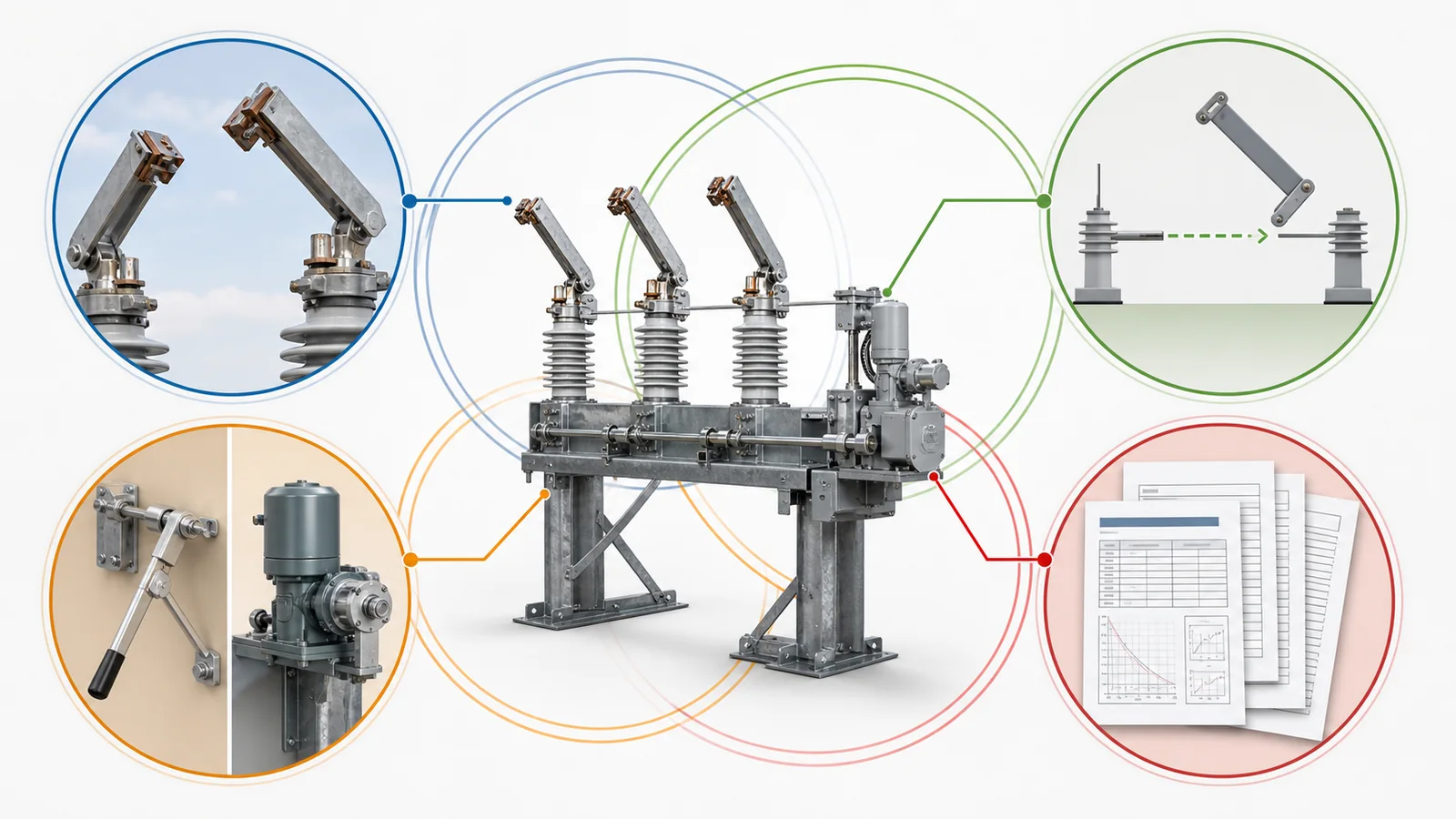
The XIYA POWER disconnect switch family likewise separates air-break, outdoor isolation, fuse, earthing, bypass, and indoor configurations. Category placement helps navigation; it does not replace duty verification.
The one-line position determines the duty. State each function explicitly instead of asking for an air break switch and expecting the supplier to infer the intended operation.
| System duty | Question to answer | Required evidence | Hold condition |
|---|---|---|---|
| Carry normal current | What is the continuous current and service condition? | Rated current and temperature-rise evidence | Rating or service basis missing |
| Make current | Can the device be closed onto the energized condition, including fault where required? | Declared making rating and test evidence | Making duty is assumed |
| Withstand fault current | What short-time and peak duty exists at this position? | Short-circuit basis and withstand ratings | Study and ratings do not align |
| Break negligible or limited current | Which small capacitive, inductive, transfer, or other current is present? | Specifically declared switching capability | Current type/magnitude is undefined |
| Break load current | Must this point open while carrying load? | Declared load-breaking rating and applicable test evidence | No matching breaking duty |
| Provide isolation | Is a visible or reliably indicated open position required? | Isolation/indication evidence | Isolation function is unverified |
| Provide grounding | Is maintenance grounding required after isolation? | Separately rated earthing function and interlocks | Grounding is assigned without evidence |
Do not conclude that every disconnector has no current-switching capability; some standards define limited duties. The usable boundary is only what the selected device specifically declares and verifies. For the foundational no-load-versus-load distinction, see disconnect switch vs load break switch. This article extends that decision to making, withstand, limited-current, isolation, and grounding evidence.
Define the current by system state, not only by normal load. A device at a line terminal, cable section, transformer branch, bus-transfer point, or maintenance boundary may face different capacitive, inductive, circulating, fault-making, or residual duties. The project engineer must identify which of those states are permitted and which upstream device owns interruption. If the proposed sequence creates a current the offered switch has not declared, the correction is to change the device, the sequence, or the system arrangement before release. It is not acceptable to infer capability from a similar-looking switch.
A no-load isolating position depends on an upstream interrupting device and a confirmed de-energized state before the disconnector operates. A rated switch or switch-disconnector may perform declared making or breaking functions within its ratings. Both need a documented functional sequence; neither product name supplies one.
| Sequence input | Isolation-only position | Declared switching position |
|---|---|---|
| Command authority | Upstream interruption precedes isolation | Direct command permitted only within declared duty |
| Permissives/interlocks | Upstream state and project conditions prevent incorrect operation | Conditions match protection and switching logic |
| Position feedback | Visible gap or verified indication | Position plus required operation/event feedback |
| Mechanism | Manual or motor operation does not change primary duty | Mechanism performance forms part of switching evidence |
| Local/remote behavior | Authority and failure state defined | Authority, control power, and fallback defined |
| Grounding boundary | Separate action after isolation and project confirmation | Separate rated function with coordinated interlocks |
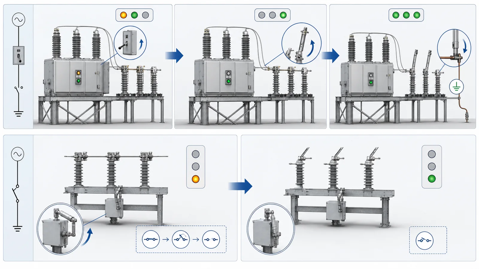
This table is a design-interface framework, not field switching instructions. The operating organization owns project switching orders, de-energization confirmation, grounding, lockout/tagout, and safety rules. For procurement, record the upstream device, permissive signals, open/closed indication, local/manual capability, control supply, auxiliary contacts, failure state, and responsibility for each transition.
Outdoor equipment often includes features that suggest design intent. Request the evidence behind each feature before assigning duty.
| Feature | What it may indicate | What it does not prove | Evidence to request |
|---|---|---|---|
| Visible blade/gap | Observable isolation state | Rated isolating distance or breaking duty | Standard, drawing, and position evidence |
| Arcing horns | Management of a specified arc duty | Load-breaking capability | Declared horn-gap duty and test record |
| Arc chute/barrier | Arc control for a declared function | Any particular breaking rating | Rating, class/category, and test report |
| Quick-break mechanism | Blade speed less dependent on operator motion | Load-breaking capability by itself | Mechanism data and tested switching duty |
| Motor operator | Remote or automated operation | Higher primary switching capability | Control supply, mechanism duty, failure behavior |
| Auxiliary contacts | Status and interlock interfaces | Reliable primary isolation on their own | Contact schedule and wiring diagram |
| Grounding blade | Integrated grounding arrangement | Earthing making/withstand rating | Separate rating, standard, and interlock evidence |
| Fuse-linked structure | Coordinated overcurrent element | Switch breaking duty or coordination | Fuse data and protection study |
| Insulators/terminals | Voltage and connection design intent | Site environmental suitability | Drawing and service-condition evidence |
Arcing horns or chutes can manage a specified arc duty, but hardware appearance does not define that duty. Motorization changes how the device is operated, not what the primary current path can make or break. Center-, double-, and vertical-break layouts, and independent-pole versus gang operation, remain separate physical-configuration decisions.
The offered assembly also needs to be evaluated as one configuration. A mechanism, blade, insulator stack, terminal pad, grounding attachment, and auxiliary switch may each have separate data, but the released rating must apply to the assembled product and its revision. Substituting one component after testing can change travel, contact force, insulation geometry, control demand, or environmental performance. Ask the supplier to identify which drawings and bill-of-material revision the rating and test evidence cover.
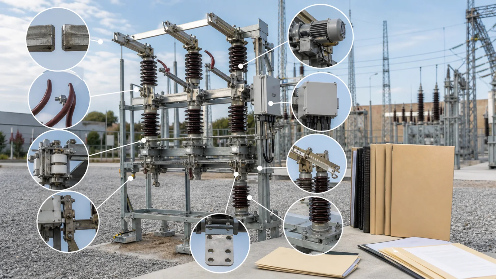
A valid comparison requires both quotations to answer the same system question. Use this approval-data checklist as the technical release data pack.
| Gate | Required input | Release evidence | Hold condition |
|---|---|---|---|
| System position | One-line location, upstream/downstream devices, switching objective | Approved one-line and project specification | Duty is described only by product name |
| Electrical basis | Rated voltage, frequency, rated current, grounding, load and fault basis | Load data and approved short-circuit study | System basis is missing or assumed |
| Exact switched current | Type and magnitude of every current to be made or broken | Duty schedule matched to manufacturer data | Current-switching requirement is ambiguous |
| Standard/ratings | Applicable standard and every required making, breaking, withstand, and isolation rating | Ratings sheet and nameplate schedule | Required duty is not declared |
| Mechanism/control | Manual, motor, stored-energy/quick-break, control supply, backup, interlocks, contacts | Mechanism and wiring schedules | Control or failure state is unresolved |
| Site/interface | Environment, mounting, terminals, phase spacing, grounding function | Current-revision drawings | Site or physical interface is unconfirmed |
| Verification | Type/design evidence, routine tests, report format, document revision | Traceable test records and document register | Evidence does not cover offered revision/duty |
For outdoor service, add the project-defined ambient, altitude, pollution, ice, wind, humidity, UV, and corrosion inputs that apply. Do not import universal limits. Also state operating frequency, maintenance/isolation responsibility, required spares, and drawing approval sequence. The distribution switching equipment overview can route the inquiry to the right product family after duty is frozen.
Traceability matters at comparison and order stages. The manufacturer data, outline drawing, mechanism schedule, nameplate schedule, and test report must identify a compatible product type and revision. Record every deviation from the project specification and show who may approve it. If the quotation references a test performed on a different construction, the supplier must provide a documented validity basis rather than a verbal statement of similarity. This turns the RFQ checklist into an auditable acceptance path instead of a list of requested attachments.
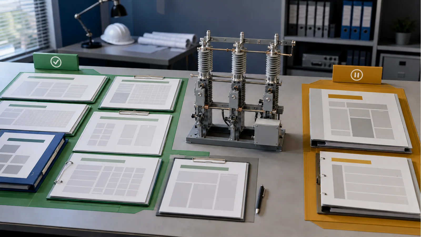
Representative engineering review, not a XIYA customer project. Two quotations both say outdoor air break switch. One data pack documents visible isolation and an operating sequence that requires upstream de-energization; it declares no required load-current breaking duty. The other identifies a specified current-switching function, matching ratings, an applicable switch standard, and test evidence for that duty.
The correct decision is not that one product name is superior. The first quotation can only be released for the isolation duty it documents. It cannot be reassigned to load interruption because the hardware looks similar. The second can only be released within its declared and evidenced switching boundary. No rating, supplier, price, customer, test result, or award is implied by this comparison.
For a duty and interface review, send XIYA POWER the one-line, required switching functions, current/fault basis, operating sequence, site conditions, mechanism/control inputs, drawings, and proposed standard/test evidence. Review identifies evidence gaps; it does not promise compliance or interrupting performance before verification.
Not reliably. Air break describes the medium or construction; disconnect switch describes isolation function. Many devices satisfy both descriptions, but the overlap cannot establish making or breaking duty. Confirm the applicable standard, declared functions, ratings, and evidence.
Only when its declared load-breaking rating, applicable product standard, and test evidence cover the project duty. Otherwise the operating sequence must assign interruption to an upstream rated device before isolation.
It makes the physical open state observable and supports isolation. It does not by itself prove rated isolating distance, absence of voltage, or current-interrupting capability. Those require project confirmation and applicable evidence.
No. They indicate arc-management hardware for some declared duty. The breaking rating and test conditions define that duty; appearance does not. Ask for the applicable category/class, rating, and test report.
Include system voltage/current/fault basis, every required making/breaking/withstand/isolation duty, standard and ratings sheet, mechanism/control interfaces, environment, drawings, and traceable type/design and routine-test evidence for the offered revision.
Specify the standard that covers the declared function in the project’s market and voltage class. IEEE air-switch, IEC disconnector/earthing-switch, and IEC switch/switch-disconnector scopes overlap but are not identical. Require the quotation, nameplate schedule, manufacturer data, and test evidence to reference the same applicable basis.



