Quotation form
Send an inquiry
Start with the basics. Our team can follow up for missing drawings, standards or packing details.
Submitted details are used only for quotation, technical review and project communication.

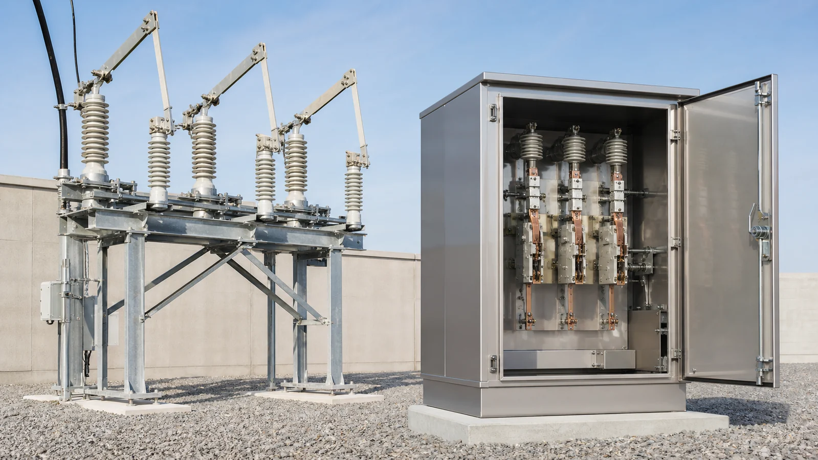
The single most important distinction between these two device families is whether the switch is rated to interrupt current under load. A disconnect switch (also called an isolator) is a no-load isolation device: it must be operated only after the circuit has been de-energised by upstream protection. A load break switch (LBS) is designed and rated to make and break normal operating current, and in many configurations fault-making current, while the circuit remains live. Mixing up these two duties is not a rating ambiguity — it is a safety and equipment-integrity boundary.
Every other difference in hardware, interlocking philosophy, and project specification follows from that one sentence.
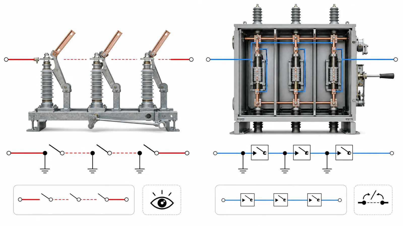
A disconnect switch provides visible or verifiable isolation of a de-energised section. Its contacts are not required to quench an arc at rated voltage and current; they are required to maintain a reliable open-gap under voltage stress after the current has already been interrupted elsewhere — by a circuit breaker, fuse, or LBS upstream. Standards such as IEC 62271-102 define disconnect switches by the absence of a current-interrupting requirement under normal service conditions. The key performance parameters are:
Because arc interruption is not required, the contact geometry is simpler — the gap just needs to be visible and mechanically stable.
A load break switch is rated to open and close a circuit carrying normal operating current at system voltage, and to do so repeatedly in service. IEC 62271-103 governs medium-voltage switch designs and distinguishes load-current breaking from fault-current breaking: an LBS is not, by itself, a fault-interrupting device. A switch-fuse combination or another coordinated protective arrangement may provide the required fault-clearing function. The key performance parameters are:
The presence of an arc-quenching mechanism — SF₆ gas, vacuum interrupter, oil, or air-blast — is what physically enables these ratings.
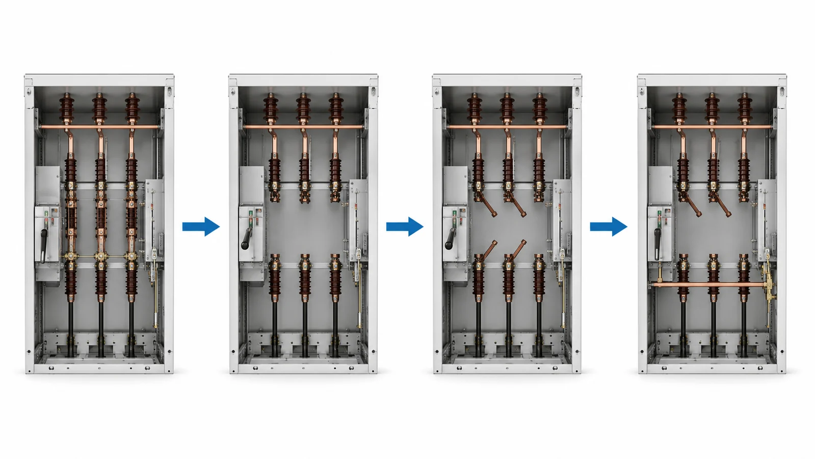
A disconnect switch contact assembly carries load current continuously but opens into a de-energised circuit. The design emphasis is on low-contact resistance for thermal performance, robust mechanical locking, and an air gap large enough to satisfy the relevant impulse and power-frequency withstand tests. Blade-type, pantograph, and centre-break isolator geometries all achieve this without arc-quenching media.
A load break switch must quench an arc at system voltage with a current that may reach several hundred amperes. The contact speed, contact travel geometry, and quenching medium are therefore engineered to a specific arc-energy envelope. A slow, large-travel blade contact designed for visual isolation would not achieve the same arc-extinction performance — the arc would simply restrike or cause contact erosion beyond any useful service life.
Because a disconnect switch cannot safely interrupt load current, most installation standards and switchgear designs enforce a mechanical or electrical interlock between the upstream circuit breaker (or LBS) and the downstream disconnect. The sequence is: open the breaker/LBS first, then open the disconnect; close the disconnect first, then close the breaker/LBS. Defeating this interlock sequence — even briefly — risks a fault-on-isolation event that the disconnect contacts are not designed to survive.
A load break switch does not carry this same constraint relative to its own contacts, because it is rated to interrupt the current it is opening. However, an LBS is still typically interlocked with upstream or downstream protection where fault-clearing capability is required at the bus level.
Disconnect switches frequently appear in switchgear lineups alongside earthing switches precisely because isolation-for-maintenance is their design mission. An earthing switch grounded through the disconnect switch frame provides a verifiable safe-working condition once isolation is confirmed. This combination — disconnect switch plus earthing switch plus upstream LBS or breaker — is a standard sequence in medium-voltage distribution substations.
For the switching scope behind load-current operation, see IEC 62271-103. The project specification and the manufacturer’s approved data sheet remain the decision source for a particular model.
When specifying or evaluating either device, the following parameters define whether a disconnect switch or load break switch is the correct selection:
System voltage (Um): Both device families carry rated voltage classifications (e.g., 12 kV, 24 kV, 36 kV). Neither can substitute for the other simply because their voltage classes overlap.
Normal current (Ir): The continuous current rating. Both device families carry normal current; the LBS must also interrupt it.
Short-time withstand current (Icw) and peak withstand current (Ipk): Both must survive fault current for the clearing time of the upstream protection device. This is a thermal and electromagnetic endurance rating, not an interrupting rating, for either device.
Load breaking current: This parameter appears on LBS data sheets; it does not appear on disconnect switch data sheets, because disconnect switches do not have this capability.
Fault-making current (Ipm): Applicable to LBS designs that include this rating. Relevant where energising into a fault is a credible operating scenario.
Operating environment: Indoor vs. outdoor, pollution level, altitude correction, seismic zone — these affect insulation coordination and mechanical design for both device families and do not by themselves determine which switching duty is required.
Switching frequency: How often load-current breaking occurs in normal service determines LBS endurance class selection. A rarely-operated tie-point switch has very different endurance requirements from a switching point operated multiple times per day.
| Parameter | Disconnect Switch | Load Break Switch |
|---|---|---|
| Interrupts load current | No — circuit must be de-energised first | Yes — rated normal current |
| Interrupts fault current | No | No (unless combined with fuse or additional rating) |
| Fault-making capacity | Not a normal isolation duty | Model and project duty dependent; confirm the declared rating |
| Arc-quenching mechanism | None required for no-load isolation | Model-specific interruption system |
| Primary design mission | Visible isolation for maintenance | Operational switching under load |
| Typical interlocking requirement | Upstream breaker or LBS must open first | Self-sufficient for load-current operations |
| Standards reference | IEC 62271-102 | IEC 62271-103 |
| Combined with earthing switch | Common | Less common, depends on topology |
No. Operating a disconnect switch on a live circuit — even at low load — risks a sustained arc that the contact geometry cannot extinguish. The result can be contact damage, flashover, or injury. Upstream switching must occur first.
No. A standard LBS is rated to interrupt normal operating current, not fault current. Where fault clearing is required, the LBS is combined with current-limiting fuses, a circuit breaker, or is specified with an explicit fault-breaking rating. Confirming fault-interruption capability requires reading the actual rated parameters, not assuming it from the LBS label alone.
Generally no, unless the LBS design includes an independently verified isolation gap and the relevant local safety rules accept it as an isolation point. Many isolation procedures and standards require a distinct, visible-isolation-capable device even when an LBS is present in the same cubicle.
Icw (short-time withstand current) is the fault current both devices must carry without damage while upstream protection operates. Breaking current is the normal load current an LBS is designed to interrupt. They are separate parameters addressing separate duties: one is endurance under fault; the other is operational interruption.
Because when contacts separate under current, an arc forms between them. An LBS must extinguish that arc reliably at rated voltage and current within a fraction of a cycle; the quenching medium (SF₆, vacuum, oil) provides the dielectric recovery and cooling that allow arc extinction. A disconnect switch opens into a de-energised gap where no arc of consequence forms, so no quenching medium is needed.
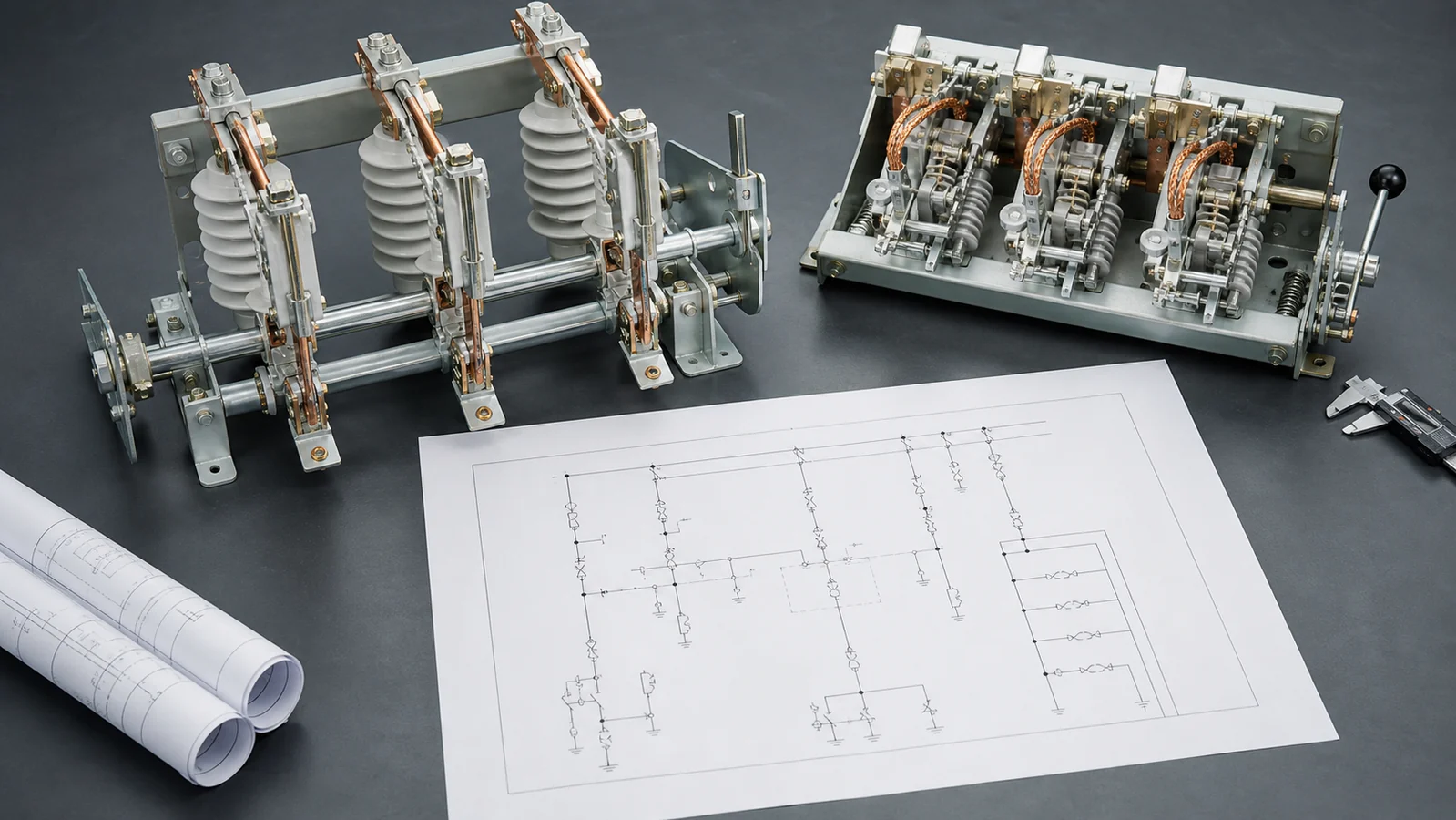
Specifying either device for a distribution project requires the following data at minimum. Gathering these inputs before contacting a manufacturer shortens the quotation cycle and avoids specification ambiguity.
For medium-voltage distribution switching equipment covering both isolation and load-switching duties, review the XIYA POWER disconnect switch range, circuit breaker family, and the distribution switching equipment hub before requesting a project-specific configuration.
Content is based on general electrical engineering practice and IEC standards. Application-specific selection should be verified against the relevant project standards, local grid codes, and the manufacturer’s published technical data.



