Quotation form
Send an inquiry
Start with the basics. Our team can follow up for missing drawings, standards or packing details.
Submitted details are used only for quotation, technical review and project communication.
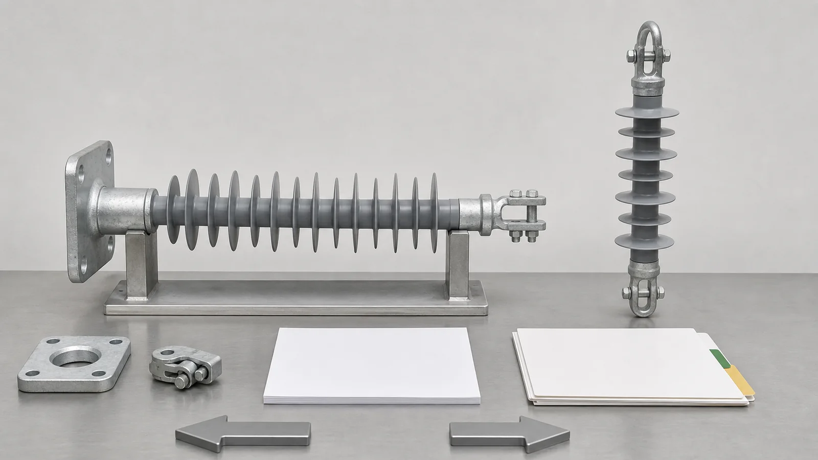
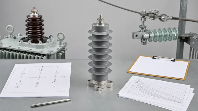
All images are generated illustrative technical visualizations, not XIYA POWER product, customer, factory, order, drawing, calculation, measurement, inspection, test, installation, commissioning, maintenance, failure, outage, or field photographs.
Composite insulator selection polluted environment decisions must connect the exact insulator function and load path to site-pollution evidence, candidate creepage and shed geometry, applicable corrections, mechanical-load definitions, fittings, and traceable records. A longer creepage number, a silicone rubber label, or a voltage match cannot release a candidate by itself.
This guide covers initial selection. It does not provide universal creepage values or diagnose contamination, tracking, erosion, hydrophobicity condition, or fitting aging in service.
Choose the route before comparing rating rows. The live composite insulator selector starts with the installation interface, then asks for insulation duty, mechanical load, fitting interface, and dimensions. Its crossarm, horizontal-line, pin, post, suspension, bushing, accessory, and material routes are not interchangeable.
| Insulator route | Primary mechanical boundary | Interface to control | Common selection error |
|---|---|---|---|
| Pin | Compression and bending at the spindle | Thread, bracket and conductor support | Reusing a post or suspension row |
| Post | Cantilever or bending at the base | Flange, top clamp and load point | Applying a rating without its lever arm |
| Crossarm or horizontal line | Combined structural actions | End fittings, clamp and support geometry | Selecting from voltage and profile alone |
| Suspension or tension | Axial tensile string duty | End fittings, section length and string geometry | Treating SML as post cantilever capacity |
| Hollow or bushing | Apparatus-specific mechanical and electrical interfaces | Flanges, conductor and enclosure boundary | Mixing hollow, wall or CT-integrated routes |
Use the wider Distribution Switching Equipment pillar to confirm the device family and duty. Then apply a five-gate selection matrix to one identified insulator candidate.
| Selection gate | Required input | Candidate evidence | Decision or hold |
|---|---|---|---|
| Application | Position, AC system basis, insulation input, function and orientation | Controlled application and interface drawing | Route confirmed or hold |
| Site pollution | Adopted method, deposits, wetting, sheltering, altitude and maintenance basis | Approved site worksheet and project specification | Site basis usable or hold |
| Creepage and profile | Total creepage, dry-arc geometry, diameter, shed profile and applicable corrections | Candidate drawing and correction worksheet | Geometry reconciled or hold |
| Mechanical and fittings | Load modes, directions, combinations, application point, core and fittings | Mechanical review and fitting drawings | Load path supported or hold |
| Evidence and release | Materials, applicable design/type evidence, revisions and deviations | Reconciled data pack and named technical release | Candidate released or hold |
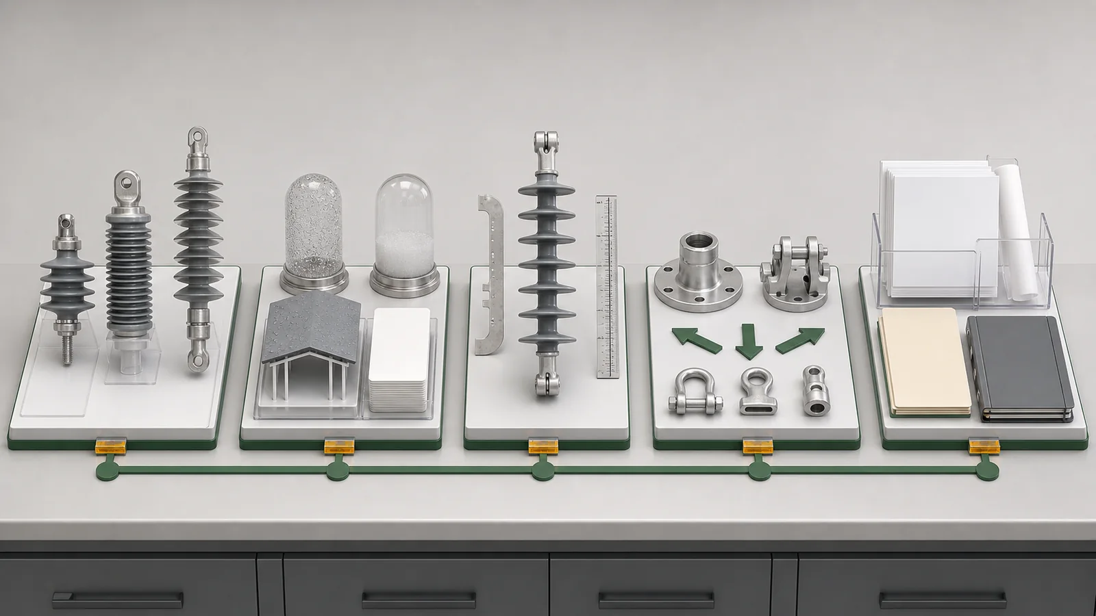
Each gate is independent. Correct flange holes cannot close a missing pollution worksheet, and a stated cantilever value cannot close an undefined load application point.
Coastal, industrial, and heavy pollution are prompts for site data, not completed specifications. Record the deposit sources, soluble or non-soluble character where the adopted method requires it, fog or condensation wetting, rain washing, drying periods, orientation, shielding, prevailing exposure, altitude, and maintenance assumptions. Distinguish exposed and sheltered surfaces rather than assigning one climate label to the whole insulator.
The official public scope of IEC TS 60815-3:2025 covers selection and relevant dimensioning of polymeric insulators for AC outdoor high-voltage systems with respect to pollution. Its public objectives include moving from site pollution severity to a reference creepage basis, choosing profiles, and applying candidate corrections for altitude, shape, size, position, diameter, shed profile, and parallel-insulator number. The summary also identifies material guidance and hydrophobicity-transfer concepts; snow and ice effects on polluted insulators are outside its scope.
That page does not supply a universal creepage value, formula, correction factor, profile limit, test criterion, or selected product. It also does not prove that a housing has hydrophobicity-transfer material behavior. Record the adopted edition, applicable family part, source worksheet, and candidate-specific calculation without reproducing paid content.
Use this chain:
The complete outdoor disconnect polluted-environment review also covers frames, coatings, mechanisms, moving joints, drainage and access. This article uses its site inputs but does not release the complete switch assembly.
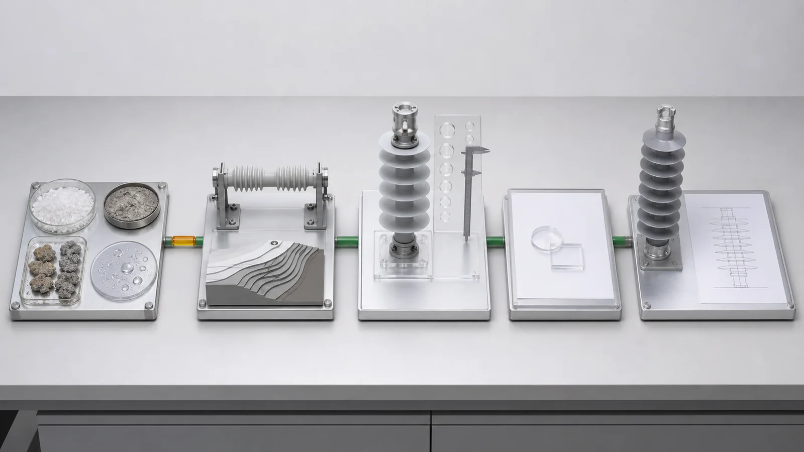
Total creepage is a drawing-controlled surface path, not a standalone quality score. Compare it with dry-arc geometry, profile, shed spacing, diameter, orientation, parallel arrangements where used, and the applicable correction record. More stated creepage does not automatically make one candidate better when the profile, orientation, diameter, or correction basis differs.
Shed profile influences how the candidate presents surfaces to deposits, wetting, sheltering, and washing. Do not publish a universal ranking of uniform and alternating sheds. Require the manufacturer to identify the actual profile and explain its applicability to the project method and orientation. The drawing should also preserve dimensions needed to verify the installed envelope and adjacent clearances.
Material names need the same discipline. Silicone rubber alone does not identify the exact housing family, core, end fittings, core-to-fitting boundary, or evidence applicability. If the supplier claims hydrophobicity-transfer material behavior, require its controlled material identity and applicable evidence. Do not convert that claim into a field hydrophobicity condition or service-life promise.
Confirm flanges, pins, threads, clamps, hole patterns, conductor interfaces, support geometry and installation envelope. A matching lower flange cannot compensate for a wrong top clamp or an unsupported load path. The surge arrester selection guide likewise keeps housing pollution and mechanical site inputs candidate-specific, but its electrical arrester selection does not supply composite-insulator data.
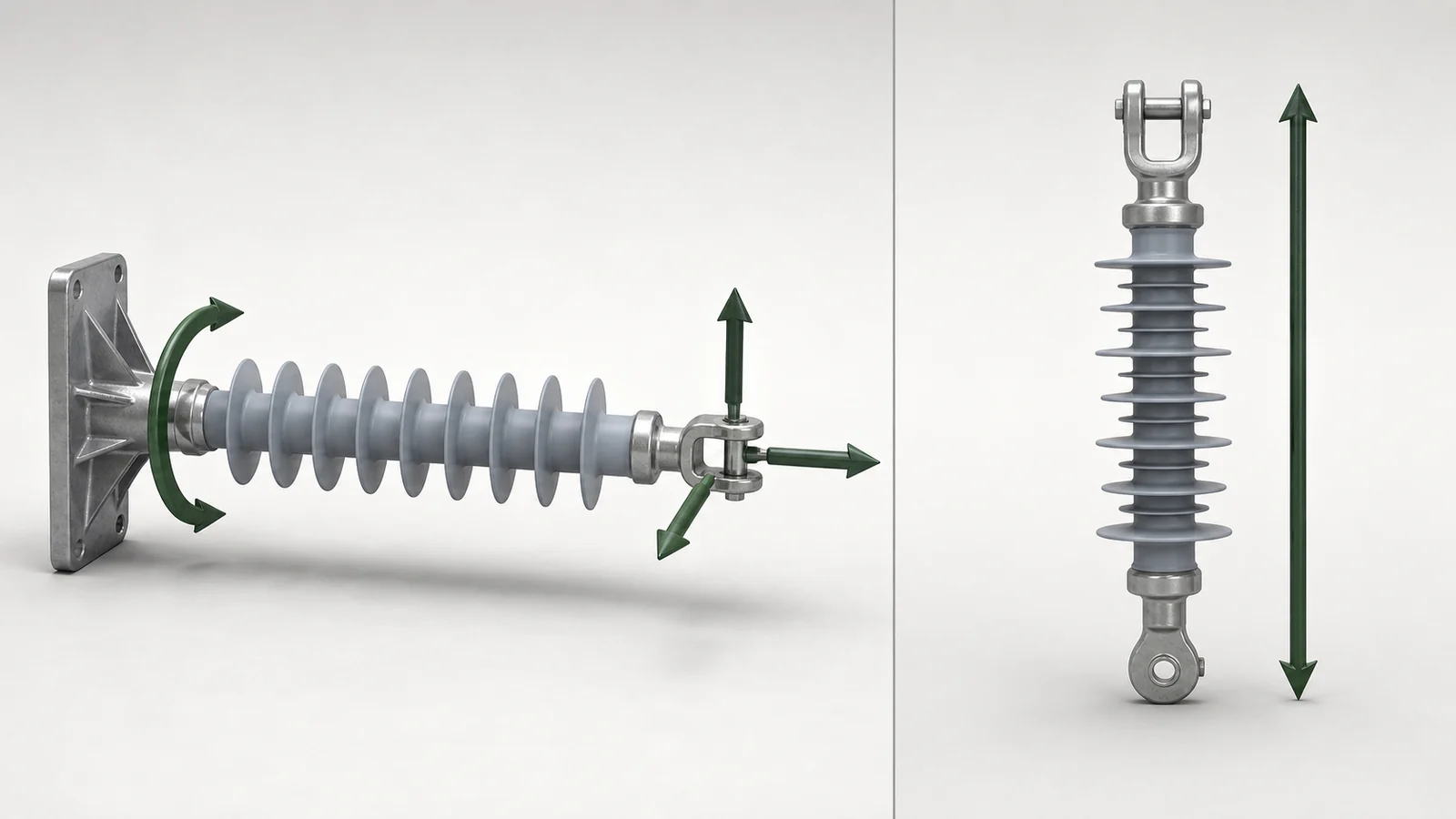
Define load modes, directions, combinations and application points before comparing capacities. A post or horizontal support develops cantilever and bending effects about its base. A suspension or tension unit carries axial string duty. A pin interface and an insulated crossarm have their own combined paths. Never transfer suspension SML to post cantilever duty merely because voltage and housing appear similar.
The mechanical schedule should identify:
A short-circuit study may provide conductor reactions for the mechanical schedule, but it does not prove the candidate’s capacity. Map those reactions to the actual connection point, then review the candidate drawing and applicable evidence. Keep the calculation basis, load definitions, combinations and named approval traceable.
Reconcile the complete fitting chain. The lower flange pattern, fasteners and structure must match, but so must the upper clamp, conductor position, orientation, fitting material, core-to-fitting construction and installation envelope. Record deviations instead of modifying a hole, clamp or lever arm without an approved review.
A useful RFQ checklist separates project inputs from supplier returns.
| Project input | Candidate return required |
|---|---|
| Application, AC voltage basis, insulation coordination and position | Exact candidate identity and controlled drawing revision |
| Site worksheet, deposits, wetting, orientation, sheltering and altitude | Creepage/profile calculation and applicable correction record |
| Insulator route and load schedule | Rating definitions, load point and combined-load review |
| Structure, flange, clamp and conductor drawings | Reconciled fitting and envelope drawings |
| Material and evidence requirements | Housing, core, fitting and boundary declarations with applicable evidence |
| Approval and deviation procedure | Deviation schedule, data-pack index and named technical release |
Ask for total creepage, dry-arc distance, diameter, shed geometry, orientation, material identity, any HTM claim basis, core and end fittings, flange and clamp dimensions, load application point, applicable mechanical rows, design/type evidence, drawing applicability, and manufacturing or routine records only where the project requires them. Missing evidence means the candidate data pack is incomplete; it does not prove that the component failed or that an activity did not occur.
Send the site data, structure drawing, load schedule, candidate requirements and open deviations through the XIYA POWER contact page for a project-specific quotation. Keep technical release separate from price comparison: the lowest quotation or longest creepage row cannot close an unresolved gate.
Representative engineering review, entirely synthetic, illustrative, and non-universal. This is not a XIYA POWER customer, supplier, factory, product, quotation, order, design, calculation, drawing approval, measurement, inspection, test, installation, commissioning, maintenance, failure, outage, or field case. No compatibility, compliance, acceptance, safety, hydrophobicity, pollution performance, mechanical capacity, service life, or result is claimed.
The synthetic application is one 36 kV-class AC outdoor horizontal line-support position on a coastal industrial feeder structure. The site file identifies salt aerosol plus industrial deposits, frequent fog wetting, partially sheltered lower surfaces, 1,450 m altitude and horizontal installation. The project route cites IEC TS 60815-1 and IEC TS 60815-3 editions but lacks the approved site-pollution worksheet.
Synthetic structure inputs are 2.2 kN vertical, 3.6 kN transverse and 1.1 kN longitudinal service actions at the conductor centerline, plus a separate 0.9 kN m interface moment. These are inputs, not allowable capacities or design factors. The mounting interface requires a synthetic 140 mm square four-hole lower flange and a controlled top-clamp drawing.
| Candidate | Returned data | Open evidence |
|---|---|---|
| A, drawing A2 | 1,050 mm total creepage, alternating sheds, 4 kN cantilever row, 140 mm square flange | No dry-arc distance, diameter, horizontal-orientation assessment, altitude/profile correction worksheet, load point, combined-load review, material/HTM declaration or top-clamp drawing |
| B, drawing B4 | 1,250 mm total creepage, uniform sheds, 5 kN cantilever row, 140 mm square flange | Worksheet is for vertical installation at 0 m; no reconciliation to horizontal 1,450 m duty, exact material/HTM applicability, core/fitting declaration, load point, combined-load review or controlled top-clamp drawing |
Hold 1: site and method. Return the approved pollution-severity basis, adopted editions, deposit and wetting evidence, horizontal orientation, sheltering, altitude and applicability route.
Hold 2: creepage and profile. Tie total creepage, dry-arc geometry, diameter, shed profile, horizontal orientation, 1,450 m altitude and every applicable correction to each candidate drawing.
Hold 3: mechanical and fittings. Reconcile all three service actions, the 0.9 kN m synthetic moment, load definitions and point, combined-load review, 140 mm flange, top clamp, core and end fittings.
Hold 4: material, evidence and release. Identify exact housing, core and fitting materials, any HTM claim basis, applicable design/type evidence, drawing revisions, deviations and named approval.
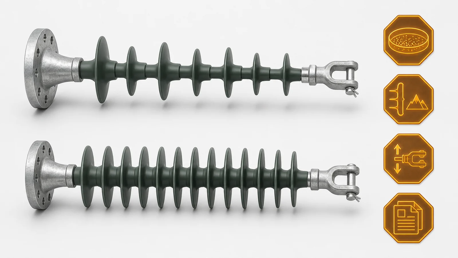
Neither candidate is selected or release-ready. All four holds remain open.
Provide the adopted site-pollution method and evidence, deposit types and sources, wetting and drying patterns, rain washing, orientation, sheltering, altitude, relevant site conditions and maintenance assumptions. Record uncertainties instead of replacing them with coastal or heavy pollution.
No. Compare total creepage with the candidate’s dry-arc geometry, diameter, shed profile, orientation, applicable corrections and site basis. A longer catalogue value with an unreconciled drawing or correction route is not a stronger selection.
Profile changes exposed and sheltered geometry, deposit collection, wetting and washing behavior. The choice must be assessed for the actual candidate, orientation and adopted project method. Do not assume uniform or alternating sheds are universally superior.
No. SML describes an axial tensile boundary for the applicable suspension route. Post duty depends on cantilever or bending capacity at a defined load application point and lever arm. Use the rating definition and evidence for the actual route.
Include load modes, directions, magnitudes, combinations, application point, lever arm and any interface moment. Add controlled lower-flange, top-clamp, conductor, support and envelope drawings, plus core and end-fitting requirements and the applicable evidence basis.
Close the site worksheet, adopted standards and editions, candidate drawing, creepage/profile and correction record, material and fitting declarations, combined-load review, interface drawings, applicable design/type evidence, deviations, data-pack index and named approval. Any missing item remains an open gate.