Quotation form
Send an inquiry
Start with the basics. Our team can follow up for missing drawings, standards or packing details.
Submitted details are used only for quotation, technical review and project communication.

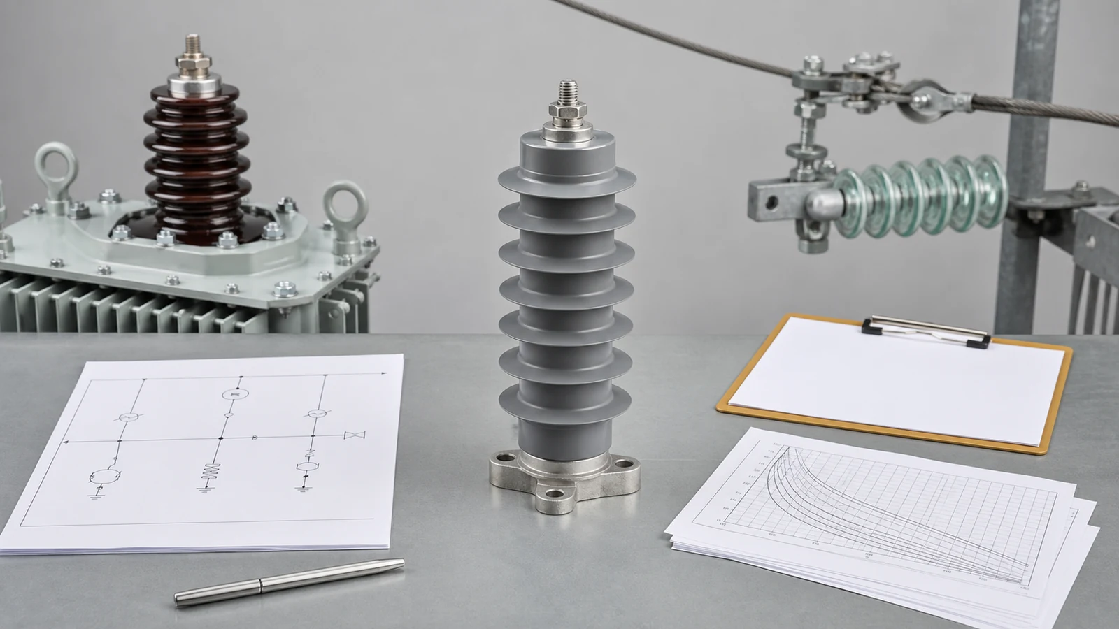
All images are generated illustrative technical visualizations, not XIYA POWER factory, product, design, test, installation, commissioning, maintenance, or field photographs.
Surge arrester selection starts with the maximum continuous phase-to-earth voltage and the temporary overvoltage envelope, not nominal system voltage alone. The offered Uc or MCOV, rated voltage Ur, protective characteristic, energy duty, site fit, and interface evidence then require separate release decisions. Closing one decision does not release the others.
First define the electrical system that the arrester will experience. Nominal line-to-line voltage identifies the network class, but it does not establish the continuous voltage across each arrester.
Grounding method, neutral displacement, and earth-fault clearing time can change phase-to-earth voltage during normal and temporary conditions. The project must also identify equipment withstand, surge exposure, site conditions, and the proposed equipment interface.
Use the surge arrester product route to organize the available line, station, housing, mounting, and monitoring options. The distribution switching equipment pillar provides the wider device-selection context. Readers needing the operating principle should begin with the basic surge arrester guide.
The following surge arrester selection matrix separates inputs from release evidence.
| Decision | Required input | Evidence source | Offered return | Release evidence | Hold condition |
|---|---|---|---|---|---|
| System basis | Nominal and highest voltage, frequency, phase arrangement | Project specification and single-line diagram | Confirmed system basis | Controlled values match | Missing or conflicting values |
| Continuous voltage | Grounding, neutral arrangement, maximum phase-to-earth voltage | Grounding study or approved system data | Uc or MCOV definition and value | Manufacturer data reconciled with system data | Grounding or continuous voltage remains open |
| TOV capability | TOV magnitude, duration, earth-fault clearing, prior duty | Project TOV assessment | Applicable TOV curve and conditions | Curve covers the project envelope | Duration, curve, or condition is absent |
| Protection | Equipment withstand and surge characteristic | Insulation-coordination basis | Protective characteristic with waveform and tolerance | Project coordination review closes | Withstand or characteristic is incomplete |
| Duty | Lightning, switching, charge, energy, and fault-current requirements | Surge study and applicable short-circuit study | Defined classifications and evidence | Offered duty matches the stated basis | Marketing label replaces controlled evidence |
| Site and interface | Pollution, altitude, ambient, mechanics, candidate location, lead geometry | Site data and project drawings | Housing, fittings, mounting, and interface documents | Product and connection data agree | Site or interface data remains open |
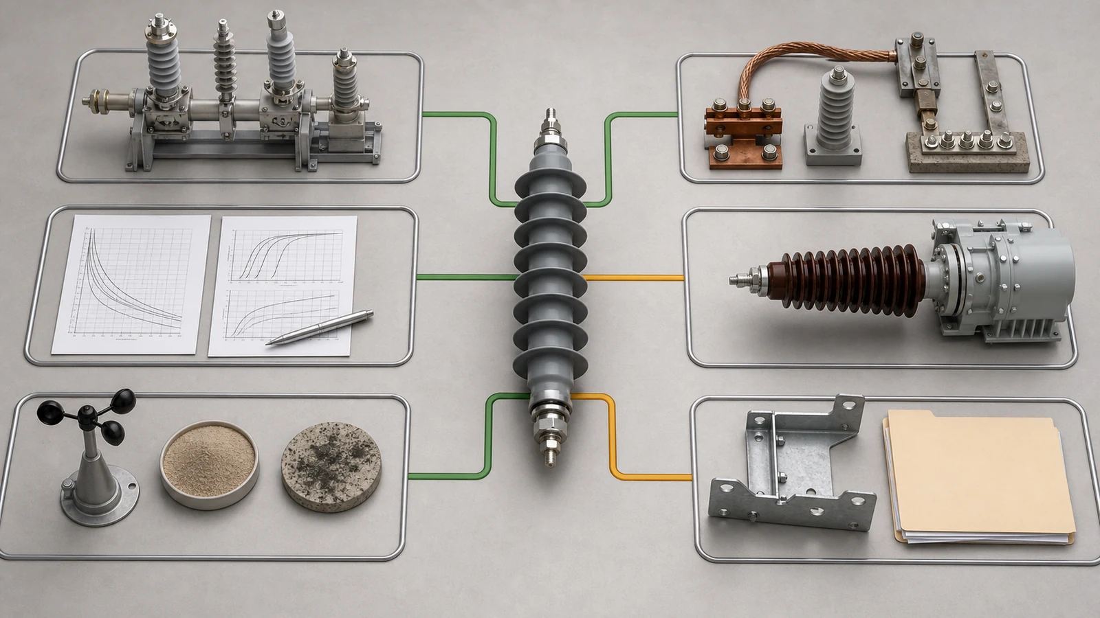
The matrix is also an RFQ control. It prevents a familiar catalogue rating from becoming an unsupported project selection.
Uc or MCOV describes the manufacturer’s continuous operating-voltage limit under its stated terminology. Rated voltage Ur is a separate arrester rating associated with temporary overvoltage and operating-duty characteristics. The manufacturer must define both values in the returned data.
Start with the maximum continuous phase-to-earth voltage at the arrester terminals. Derive it from the approved system and grounding basis, including any normal neutral displacement. Do not select it from nominal line-to-line voltage alone.
Next compare the project TOV envelope with manufacturer capability. The return should identify TOV magnitude, duration, prior energy or operating duty, and any temperature assumption relevant to the curve. A curve for a different prior-duty condition does not close the review.
The official IEC 60099-4:2014 page covers gapless metal-oxide arresters for a.c. circuits above 1 kV. Its public scope establishes the product-standard context. It does not choose project ratings or replace manufacturer curves and system studies.
A higher Uc or Ur may improve tolerance of continuous voltage or TOV. It can also raise the offered protective characteristic. Therefore, adding voltage margin is not automatically a better coordination decision.
Use this evidence sequence:
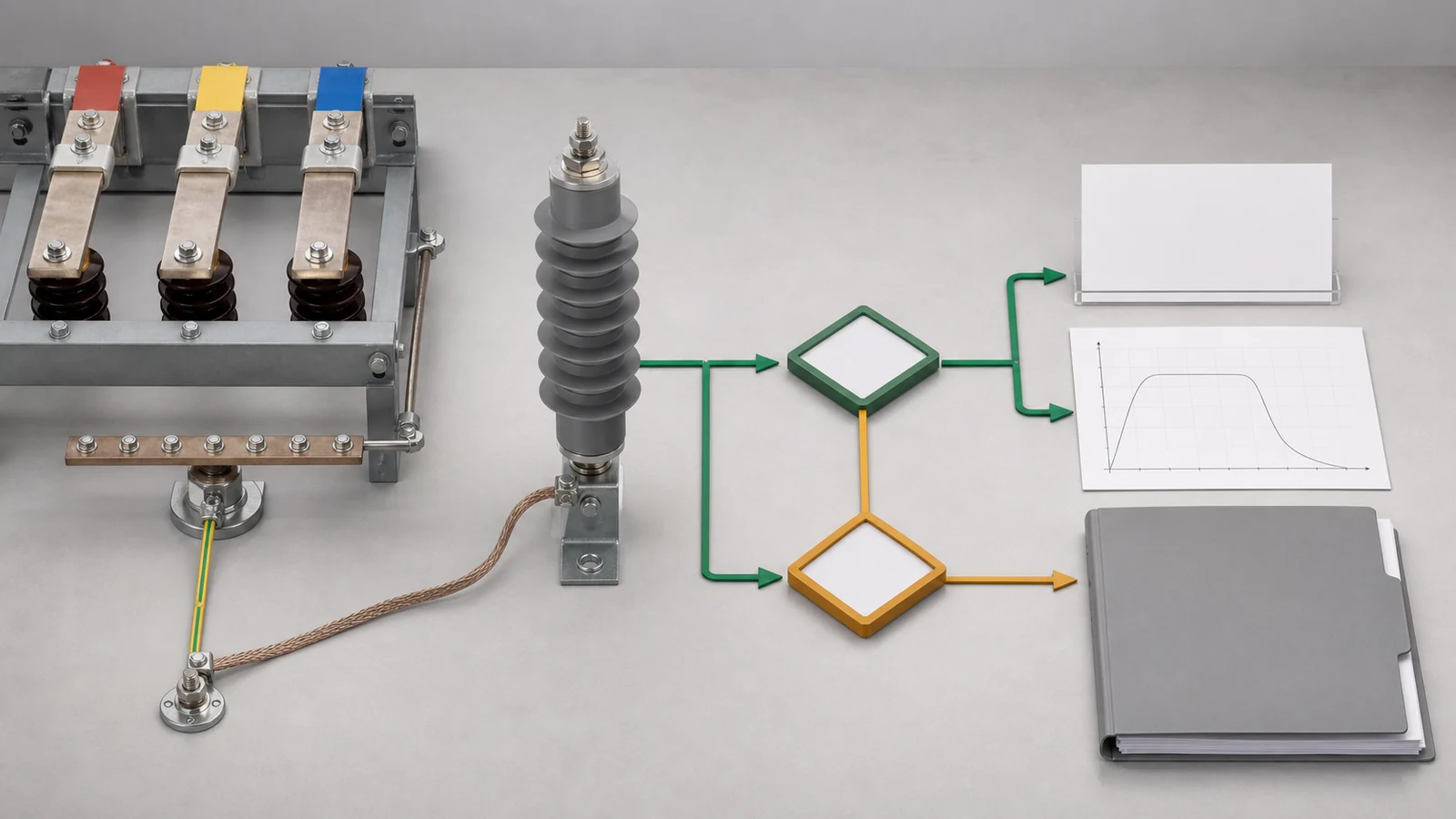
Do not convert this sequence into a universal Uc-to-Ur ratio. Product families and manufacturer definitions must remain visible in the review.
The offered protective or residual voltage is meaningful only with its test current, waveform, amplitude, and tolerance. A value quoted at one condition cannot silently represent every lightning or switching event.
Compare the appropriate characteristic with the protected equipment’s applicable withstand data. The project specification or insulation-coordination study should define the required coordination allowance and the conditions used in that comparison.
The arrester-terminal voltage is not always the equipment-terminal voltage. Candidate location, conductor geometry, earth-lead geometry, and surge reflections can affect the effective stress at the protected terminal. The project study must address these effects where material.
DSE-14 treats the candidate interface and geometry as required inputs. It does not prescribe the final position at a transformer, cable transition, overhead line, or switchgear panel. That decision belongs to the dedicated placement article scheduled next in this cluster.
The protection evidence chain should therefore show:
| Evidence step | Required return | Decision |
|---|---|---|
| Arrester characteristic | Protective voltage with current condition, waveform, and tolerance | Confirm the value being compared |
| Equipment withstand | Applicable impulse or other withstand data | Confirm the protected boundary |
| Project allowance | Approved coordination criterion | Define the release basis |
| Interface effects | Candidate location and connection geometry | Determine whether additional stress needs study |
| Technical release | Signed or controlled review state | Release protection only when the chain closes |
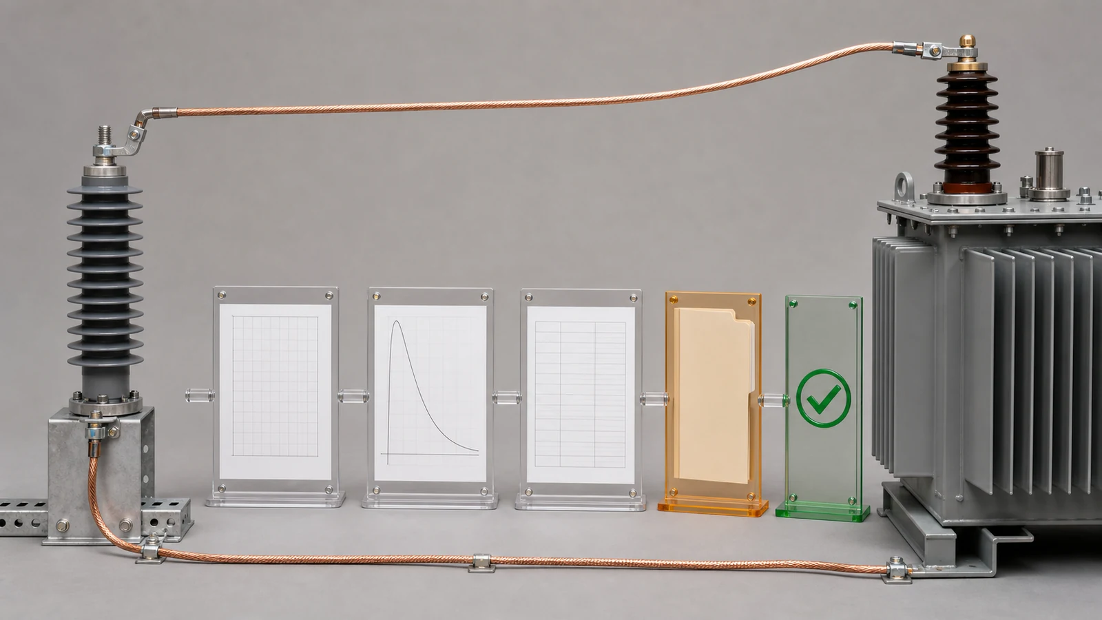
An offer can pass the Uc and TOV review yet remain on hold here. Likewise, a low residual-voltage value cannot compensate for inadequate continuous-voltage or TOV capability.
Do not collapse every surge-duty requirement into nominal discharge current. Each returned value answers a different engineering question.
Terminology and classifications can depend on the applicable standard edition and product family. The supplier should cite manufacturer data and the project specification for the offered duty. Where pressure-relief duty applies, reconcile it with the relevant short-circuit study.
Phrases such as heavy duty or high energy are not release evidence by themselves. The offer should return the defined class, value, test basis, and document reference requested by the project.
Keep the selection logic explicit. A suitable continuous-voltage rating does not prove adequate energy duty. A high current-class label does not prove the required switching or repetitive-charge performance.
Electrical ratings are only part of the selection. The product construction and physical interface must fit the actual site.
State whether the application calls for a line or station arrester. Specify the project basis for polymer or porcelain housing, pollution performance, creepage, altitude, ambient temperature, solar exposure, seismic demand, wind, ice, and terminal loads.
Define mounting orientation, brackets, line and earth terminals, conductor fittings, and any disconnector. Also identify event counters, leakage-current monitors, communication interfaces, and auxiliary power where they are part of the scope.
The high-voltage equipment RFQ checklist explains the wider project data pack. Available product documents can be requested through the catalogs and resources page.
Use an arrester-specific RFQ checklist to control the return.
| Data pack item | Required input or offered evidence | Hold condition |
|---|---|---|
| Rating datasheet | Uc or MCOV, Ur, frequency, current and duty classifications | Definitions or values are missing |
| TOV evidence | Capability curve, duration, prior-duty basis, applicable conditions | Project TOV point cannot be checked |
| Protection evidence | Protective characteristics with waveform and tolerance | Comparison basis is incomplete |
| Duty evidence | Charge, energy, operating-duty, and fault-duty evidence as specified | Uncontrolled marketing description is returned |
| Site declaration | Housing, pollution, altitude, ambient, solar, and mechanical basis | Site deviation is undeclared |
| Interface drawings | Dimensions, mounting, terminals, fittings, accessories, candidate geometry | Equipment interface cannot be reviewed |
| Test and document return | Specified type or design evidence, routine-test commitment, revisions, deviations | Evidence scope or status remains open |
Technical release should identify each closed decision and each residual deviation. A complete-looking datasheet is not enough when its conditions do not match the project basis.
Representative engineering review, not a XIYA POWER customer, supplier, factory, product, design, test, installation, commissioning, maintenance, failure, or field case. All system values, offered ratings, protective levels, withstand levels, document states, candidate interfaces, findings, and decisions are illustrative and non-universal.
The synthetic system is one 22 kV feeder with 24 kV highest system voltage at 50 Hz. The offer lists Uc or MCOV at 19.2 kV and Ur at 24 kV. It also lists a 10 kA nominal discharge current and a 72 kV residual voltage at the stated current condition.
The protected transformer schedule lists a 125 kV lightning impulse withstand level. The grounding field is blank. The illustrative project study requests a TOV check at 20.5 kV phase-to-earth for 10 seconds.
No matching TOV curve or prior-duty condition is returned. The offer says high energy without a defined class, charge-transfer value, thermal-energy value, or cited evidence. The single-line diagram marks the transformer high-voltage terminal as a candidate interface. Conductor and earth-lead geometry are absent.
| Decision | Observed return | Release state | Required evidence | Hold condition |
|---|---|---|---|---|
| Uc/Ur and TOV | 19.2 kV Uc, 24 kV Ur, blank grounding field, unmatched TOV point | Hold | Grounding, continuous voltage, matching TOV curve, prior-duty basis | Voltage and TOV evidence does not close |
| Protection coordination | 72 kV characteristic and 125 kV withstand listed | Hold | Waveform, tolerance, project allowance, interface effects | Comparison chain remains incomplete |
| Energy duty | 10 kA listed and high energy stated |
Hold | Defined class or values and cited duty evidence | Current rating does not define energy duty |
| Location interface | Candidate transformer terminal shown | Hold | Conductor and earth-lead geometry | Placement interface cannot be assessed |
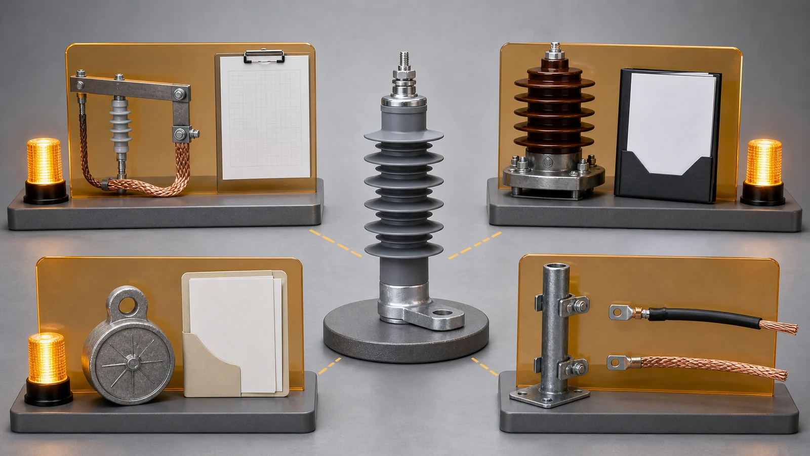
The review does not declare the offered arrester correct or incorrect. It does not calculate a protective margin. It shows why four unanswered decisions require four controlled closures.
Provide system voltage, frequency, grounding, continuous phase-to-earth voltage, earth-fault duration, TOV envelope, equipment withstand, surge duty, site conditions, and interface geometry. The manufacturer must return corresponding rating, capability, characteristic, duty, and document evidence.
No. Grounding and neutral behavior determine the continuous and temporary phase-to-earth voltage across the arrester. Select Uc or MCOV against that controlled basis and the manufacturer evidence.
Uc or MCOV is the manufacturer’s continuous operating-voltage rating. Ur is a separate rated voltage associated with the product’s stated TOV and duty characteristics. Use the definitions supplied for the offered product.
Compare every controlling project TOV magnitude and duration with the applicable manufacturer curve. Confirm grounding, prior-duty assumption, temperature basis, and any other stated conditions before release.
No. Lower protective voltage can improve coordination, but the selected arrester must also satisfy continuous-voltage, TOV, energy, and site requirements. Optimize the decisions together, then release them separately.
Hold the relevant decision when system data, TOV curves, protective characteristics, duty evidence, site declarations, or interface documents are incomplete or conflicting. Closing one hold must not silently close another.



