Quotation form
Send an inquiry
Start with the basics. Our team can follow up for missing drawings, standards or packing details.
Submitted details are used only for quotation, technical review and project communication.

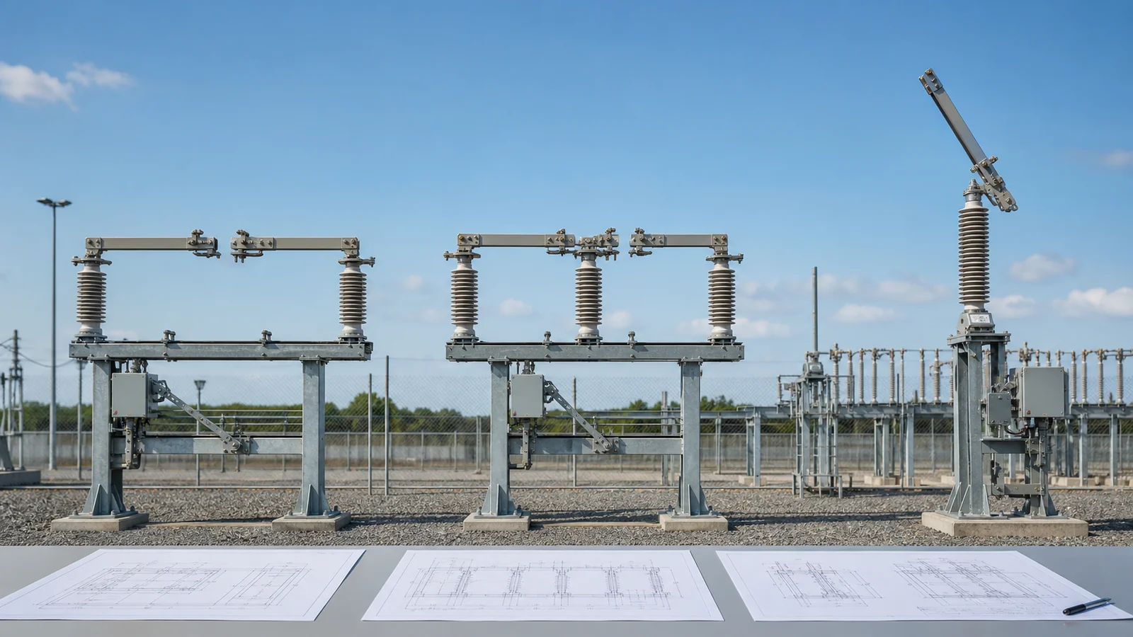
Comparing disconnect switch types – center break, double break, and vertical break – starts with the complete bay envelope, not the type name. A common center-break design opens sideways at the center. A common double-side-break design rotates a center current path away from two fixed contacts. A vertical-break design opens upward. Each movement shifts the critical space, support, terminal, and access checks to a different part of the bay.
This article assumes disconnector duty is already established. Use the Distribution Switching Equipment pillar and the scheduled air-break switch versus disconnect switch guide when the device class or switching duty remains open.
Manufacturer terminology and mechanical details vary. Therefore, treat the common geometry as an orientation aid and use the offered open/closed drawings as the release basis.
| Bay question | Required input | Architecture effect | Decision and release evidence | Hold condition |
|---|---|---|---|---|
| Where are the terminals? | One-line, plan/elevation, terminal coordinates and direction | Fixes blade orientation and bus connection | Manufacturer coordinate drawing overlaid on the bay | Coordinates or bus interface differ |
| What phase spacing is available? | Civil/structural layout and clearance basis | Side-opening paths compete for horizontal space; vertical opening shifts demand upward | Open-state plan/elevation overlay | Swept path enters an unverified boundary |
| What is above and beside the device? | Gantry, conductor, fence, adjacent-bay and access envelopes | Determines whether horizontal or vertical movement is obstructed | Common constraint overlay | Obstruction survey is incomplete |
| How is the device supported? | Base, bolt pattern, support steel and reaction data | Each arrangement places supports and loads differently | Civil interface review | Base or reaction data is missing |
| What loads reach the terminals? | Bus arrangement, manufacturer data and approved electrical basis | Influences terminal/support interface and bus flexibility | Accepted load/interface record | Offered basis does not match the project |
| Where are operating and earthing interfaces? | Operating side, mechanism/linkage and earthing drawings | Affects shafts, access and moving envelopes | Interface drawing on bay plan | Linkage or earthing path conflicts |
| How is the device accessed? | Inspection, adjustment, lifting and removal envelope | Contacts and moving parts require different access directions | Maintainability overlay | Required access is not demonstrated |
| What proves fit? | Project specification, adopted standard, deviations and applicable evidence | Converts a type label into a release decision | Controlled comparison register | Evidence is generic or for another design |
The matrix should compare all offers on one drawing scale and one coordinate system. A product photo can identify a likely architecture, but it cannot prove terminal locations, blade travel, clearances, reactions, or access.
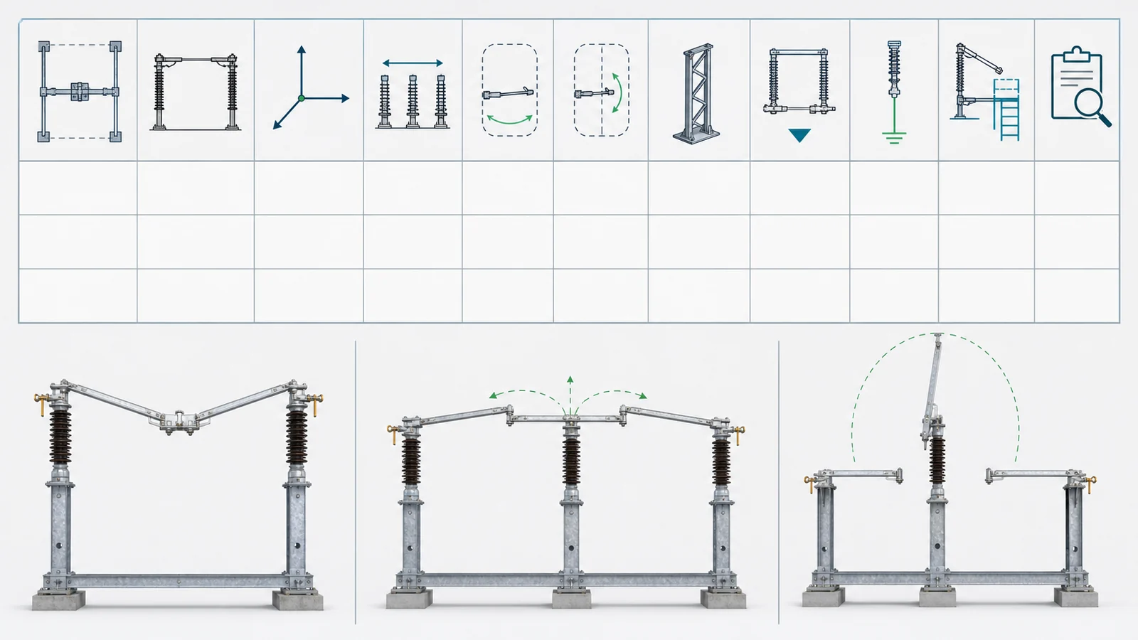
The live Outdoor Disconnect Switches page shows that outdoor isolation products use several physical structures. Confirm the isolation-versus-interruption boundary separately through the disconnect switch versus load-break switch foundation.
In this comparison, double-break means the common double-side-break arrangement, not every product with two contact interfaces.
| Comparison point | Center-break – common arrangement | Double-side-break – common arrangement | Vertical-break – common arrangement |
|---|---|---|---|
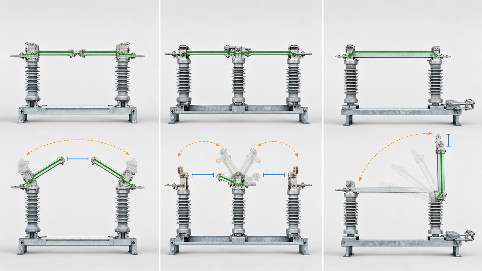
| Moving current path | Two sides rotate horizontally and separate at the center | Center support rotates a current path away from two outer fixed contacts | Blade swings upward and may rotate about its longitudinal axis during travel |
| Open gaps | One central isolating gap | Two side gaps in series | One gap created by the raised blade/contact separation |
| Typical layout benefit | Versatile parallel, diagonal or in-line adaptation | Low-profile horizontal layout where phase space is constrained and vertical travel is unavailable | Reduced phase spacing can be possible when overhead space is available |
| Critical clearance risk | Side sweep and open arms can enlarge phase/bay width | Two-end contact span, center rotation and base footprint must fit one envelope | Open blade and full swept path must clear conductors, gantries and structures above |
| Support/terminal review | Two rotating sides and center-contact alignment | Three-support base, two fixed contacts and center drive path | Offered hinge/contact/support geometry and bus interface |
| Maintenance focus | Center contact, arm alignment, bearings and stops | Both fixed contacts, center support, linkage and alignment | Hinge, raised contact, counterbalance/linkage and overhead access as applicable |
| Minimum drawing proof | Plan overlay in open and closed positions | Plan overlay plus base/terminal/support data | Open-state elevation plus vertical swept envelope |
No column is universally smaller, stronger, cheaper, or easier to maintain. A reduced phase pitch can be offset by base width, longitudinal terminal span, overhead space, structure modifications, access, or the manufacturer’s particular design.
The official IEC 62271-102:2018 page says the standard applies to AC disconnectors and earthing switches for indoor and outdoor installations above 1,000 V at service frequencies up to and including 60 Hz. Its public change summary includes isolating-distance requirements, position indication/signalling, interlocking, ice-coating ratings, and revised tests. It does not choose a break architecture for a bay or publish the project clearances and dimensions needed here.
Build one plan/elevation overlay for each offered design:
| Interface | Check | Evidence | Hold trigger |
|---|---|---|---|
| Terminal coordinates and direction | Match rigid/flexible bus connection points | Offered terminal drawing against bay/bus layout | Transition or rerouting is unreviewed |
| Phase and earth boundaries | Check every moving part through full travel | Open/closed plan and elevation plus project clearance basis | Any swept envelope enters a boundary |
| Overhead and side constraints | Include conductors, gantry, fence, adjacent equipment and access | Survey/design envelope on the same coordinate system | Constraint is absent or outdated |
| Terminal loads | Compare declared directions and bases with bus/support design | Manufacturer load data tied to the offered configuration | Values or basis are incomplete |
| Base and support reactions | Match bolt pattern, support points and reactions | Outline/base drawing and structural interface record | Existing or new support cannot be checked |
| Earthing and mechanism interfaces | Check separate moving paths and drive routes | Combined interface drawing | Physical conflict remains |
The project specification and adopted standard define acceptance. Manufacturer data defines the offered geometry and declared loads. The short-circuit study may supply part of the approved electrical and mechanical basis, but it does not decide layout by itself. Do not transfer terminal or base data from a different model, voltage variant, insulator arrangement, or revision without an applicability record.
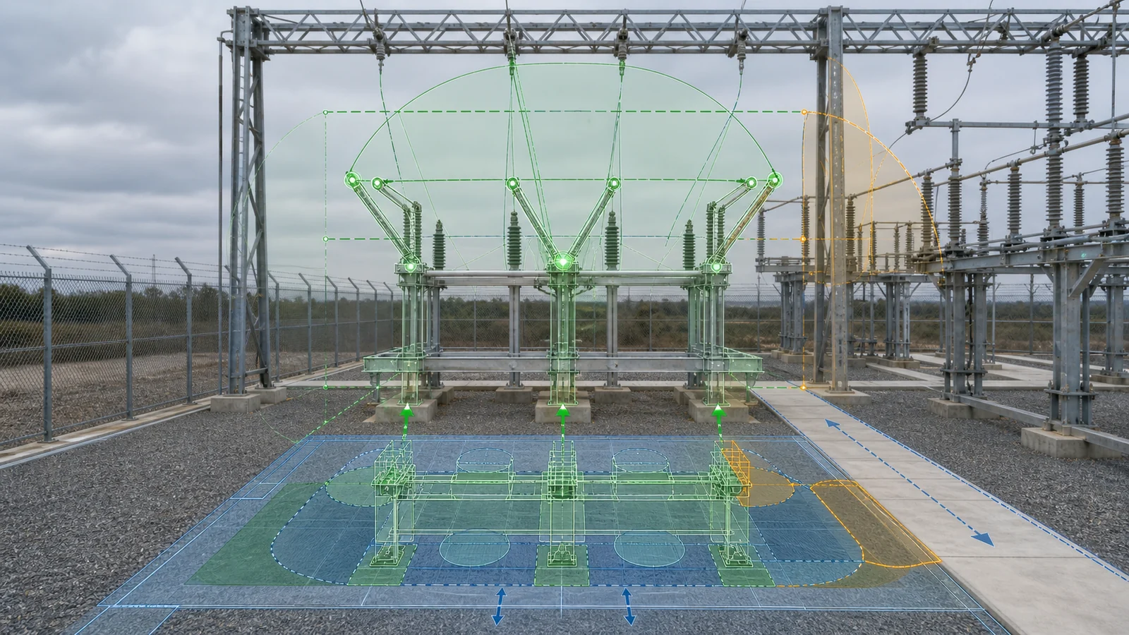
Break geometry does not determine the complete operating arrangement. For each offer, locate the mechanism, operating side, drive shaft or linkage, local/manual access, position indication, interlock interface, earthing-switch attachment, and every moving part on the same bay drawing.
Check visibility of the actual open position from the agreed observation point without assuming that one architecture is always easier to see. Confirm that shafts and linkages clear support steel, cable routes, walkways and neighboring equipment. Where an earthing switch is integral or separately mounted, overlay its blade path as well as the main disconnector path.
Maintainability is also three-dimensional. The review should show access for contact inspection, blade alignment, bearing or linkage adjustment, lifting, and component removal. A device can fit electrically in its normal position yet remain unsuitable because the open blade obstructs an access route or a contact cannot be reached within the available maintenance envelope.
Independent-pole versus three-pole gang operation is a separate decision. Break geometry alone neither selects nor proves that arrangement. The offered mechanism and coupling drawings must demonstrate the project’s pole-operation requirement; DSE-09 will own that comparison.
Use one shared input package and require every supplier to return the same layout evidence.
Shared project basis:
Per-offer return:
Normalize the manufacturer data against the same project specification and short-circuit study basis. Keep ratings outside this layout comparison: each offer should use the already approved electrical schedule. Technical release requires one overlay register that records fit, accepted exceptions, hold items, owners and release evidence rather than three unrelated catalog drawings.
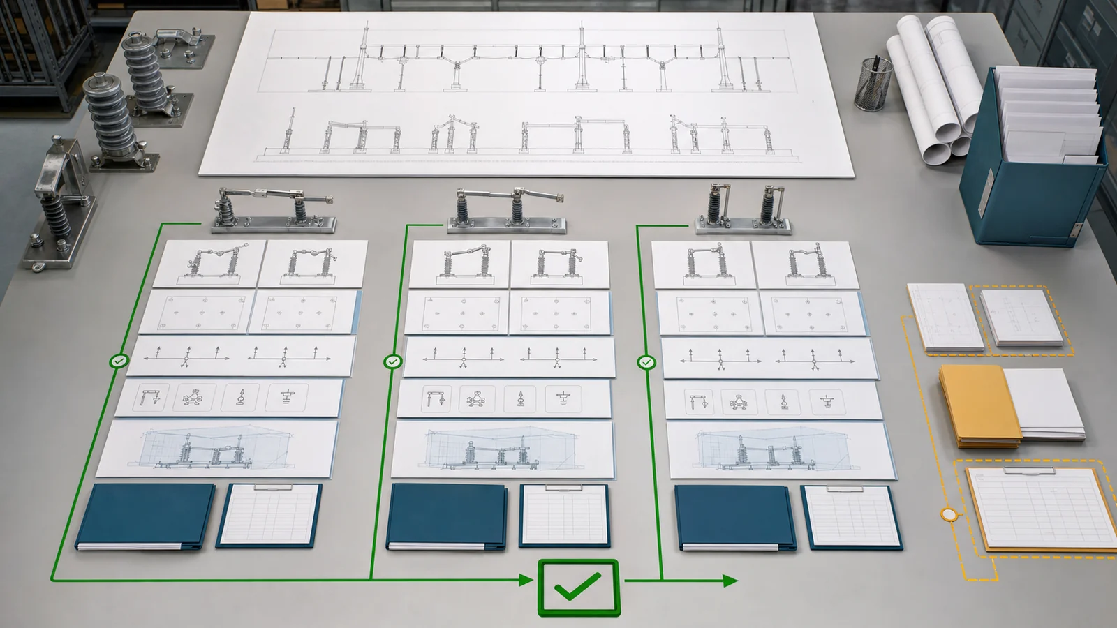
Representative engineering review, not a XIYA POWER customer project, factory case, field record, commissioned installation, substation result, or service result.
A brownfield outdoor bay has fixed terminal coordinates, existing support steel, adjacent phase/bay envelopes, overhead conductor and gantry constraints, an operating-side access lane, and an earthing-switch interface. Three offers are named center-break, double-break and vertical-break, but their drawings are not normalized on the same bay basis.
The center-break overlay indicates that its side sweep may approach an adjacent envelope, but the required clearance comparison is incomplete. The double-break option appears to fit the phase pitch, yet its three-support base, terminal coordinates, loads and reactions are not reconciled with the existing interface. The vertical-break option appears to reduce horizontal demand, but the open blade and full swept path have not been checked against the overhead conductor and gantry envelope.
Decision: hold architecture selection. Reconcile:
No type is selected, and no dimension, rating, supplier, price, test, installation, outage or service outcome is assigned. For a project-specific comparison, send the controlled bay layout, terminal schedule, constraint survey, electrical basis, service conditions and offered drawings through the XIYA POWER contact page.
A common center-break uses two horizontally rotating sides that separate at one center gap. A common double-side-break uses a rotating center current path and two fixed side contacts, producing two gaps. Compare their complete side sweep, terminal span, base and support interfaces on the actual bay drawing.
Its moving path is primarily vertical rather than extending between neighboring phases in plan view. That can reduce horizontal phase demand, but only if the raised blade, swept path and required clearance fit below overhead conductors and structures.
No. It may reduce phase spacing in some layouts, but total fit also depends on terminal span, three-support base, bus arrangement, structure reactions, access and the manufacturer’s geometry. Compare one plan and elevation basis.
No. A V-type is a particular structural variant associated with center-opening geometry in some product families. Other center-break designs use different bases, arm positions and pivot geometry. The manufacturer’s drawings control the classification and swept path.
Require the project bay plan/elevation plus each offer’s open/closed/swept-envelope drawings, terminal-coordinate drawing, outline/base and reaction data, terminal-load record, mechanism/earthing interface, and maintenance/removal envelope.
No. It defines the current-path movement and open-gap arrangement. Pole-operation mode is a separate project and mechanism decision. Verify that the offered drive and coupling arrangement meets the requirement without assuming it from center-, double-, or vertical-break geometry.



