Quotation form
Send an inquiry
Start with the basics. Our team can follow up for missing drawings, standards or packing details.
Submitted details are used only for quotation, technical review and project communication.

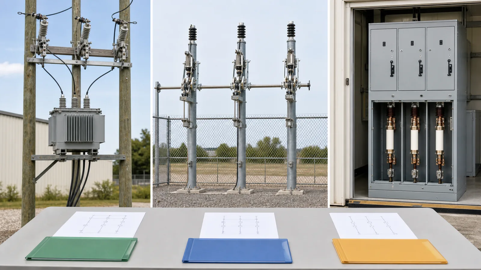
The comparison of a fuse disconnect switch vs fuse cutout cannot be resolved from product names alone. A drop-out cutout, an outdoor fuse-disconnect assembly, and a three-pole switch-fuse combination can all place a fuse near a visible open point, but they differ in pole operation, fuse technology, normal switching duty, protective interruption, trip or release behavior, installation, and evidence. Start with the feeder position and physical topology, then verify the complete offered configuration.
Fuse disconnect switch is a commercial label, not a complete engineering definition. The live Fuse Disconnect Switches category includes high-voltage fuse-type disconnects, HRC fuse-switch combinations, and low-voltage arrangements. Their shared category does not make their functions interchangeable.
Before using a selection matrix, obtain:
A drop-out fuse cutout is normally identifiable by its cutout body, hinged fuse tube, and expulsion fuse link, applied phase by phase on an overhead branch or transformer lateral. A switch-fuse combination in this article means a three-pole functional assembly of a switch or switch-disconnector with current-limiting fuses. A fuse disconnect switch sits between those clear definitions only after the supplier identifies what the offered assembly actually contains.
Use the distribution switching equipment family map for product context. Keep DSE-11’s decision narrower: identify the fused topology and its application boundary rather than compare every feeder device.
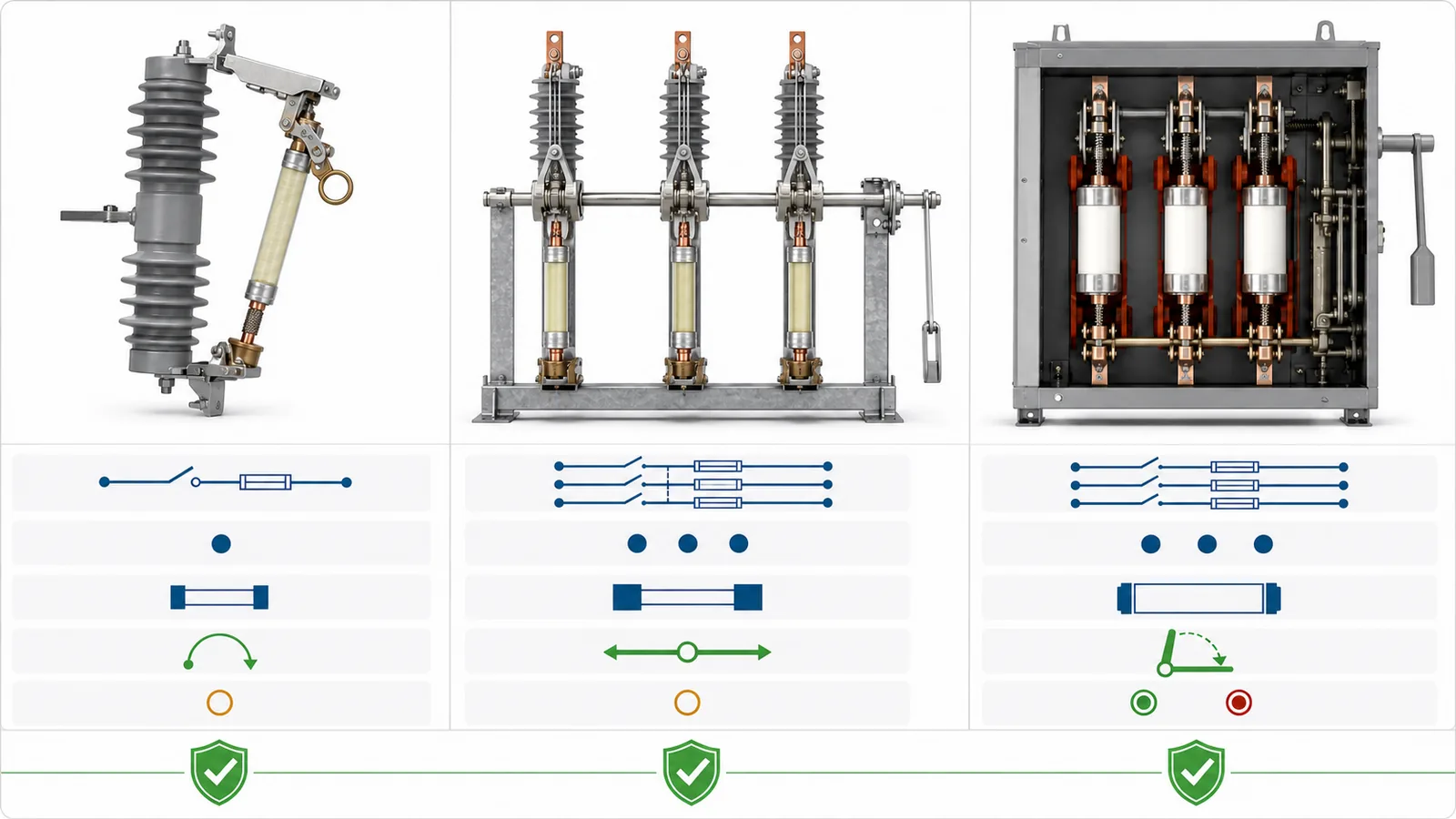
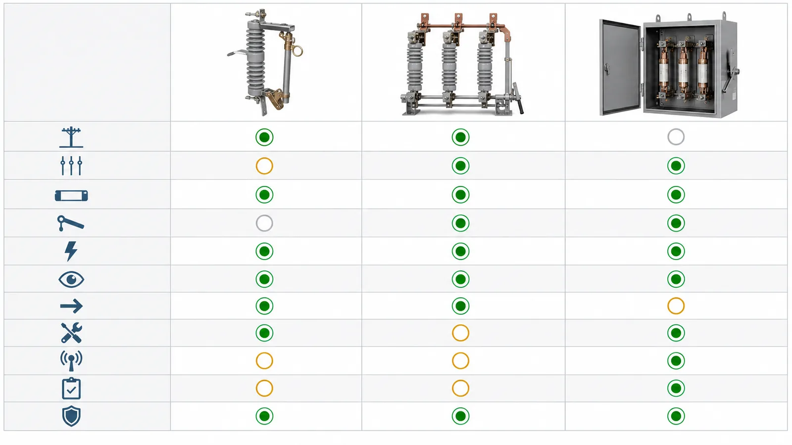
The following comparison describes typical boundaries, not universal placement or ratings:
| Review axis | Drop-out fuse cutout | Fuse disconnect switch label | Three-pole switch-fuse combination |
|---|---|---|---|
| Typical position | Overhead branch or pole-mounted transformer lateral | Outdoor spur or distribution point after configuration is defined | Indoor/enclosed transformer feeder, RMU, or compact substation |
| Pole behavior | Commonly one cutout per phase | Independent or gang-operated; must be declared | Three-pole functional assembly |
| Fuse technology | Expulsion fuse link in a fuse tube | Expulsion, HRC, or current-limiting arrangement; label does not decide | Current-limiting fuses as part of the combination |
| Normal switching | Only the duty specifically declared for the offered cutout and operating method | Must be separately declared for the exact assembly | Switch or switch-disconnector performs declared making/breaking duty |
| Protective interruption | Fuse link and complete cutout interrupt within declared capability | Depends on fuse and assembly configuration | Complete combination performs its declared protective interruption |
| Open indication | Dropped tube gives phase-specific indication | Blade, tube, or mechanism indication varies | Three-pole switch/mechanism indication as designed |
| After fuse operation | Affected phase tube may drop | Response depends on topology | Striker/release may open all poles where included and evidenced |
| Maintenance | Pole access, tube and link replacement | Structure, mechanism, fuse access, and replacement method vary | Enclosed access, fuse replacement, interlocks, and mechanism review |
| Automation | Usually limited unless a separate system is provided | Remote or motor operation must be declared | Control and indication options depend on the complete assembly |
| Minimum evidence | Cutout/link data, fault basis, coordination, drawing | Topology, fuse data, pole operation, switching duty, drawing | Combination rating, fuse range, switch interface, release response, evidence |
| Hold condition | Link/holder, coordination, or interrupting basis is open | Commercial label remains unresolved | Only separate component sheets are supplied |
Feed the result into the distribution feeder equipment selection matrix rather than treating this table as the complete system decision. DSE-01 assigns isolation, normal switching, protection, fault interruption, and reclosing at feeder level; this article resolves only the fused-device branch of that decision.
The RFQ checklist should name each required input, source, owner, returned manufacturer data, and technical-release condition. At minimum, provide the one-line, system voltage and frequency, phase operation, service conditions, load-switching requirement, available fault basis from the short-circuit study, protection and coordination responsibility, isolation/indication requirement, mechanism, mounting drawing, and project specification.
Record the decision by position, not only by model. Each returned row should identify the proposed topology, exact configuration, supplier claim, evidence reference and revision, applicability review, open deviation, responsible reviewer, and release disposition. If the fuse family, pole arrangement, or mechanism changes, reopen every affected row instead of carrying forward the earlier acceptance. An accepted label is not an accepted current path. The release package should let another reviewer trace why the position was accepted, what remained excluded, and which controlled drawing and data sheet govern the ordered assembly.
A drop-out fuse cutout is the candidate when an overhead branch or transformer lateral needs phase-by-phase fuse protection and visible drop indication, and when the complete cutout/link package matches the system, fault, environmental, and coordination inputs. The Drop Out Fuses owner page covers body, insulation, mounting, enclosure, and fuse-link product choices without deciding the project coordination.
Separate protective interruption from manual switching. The fuse link interrupts overcurrent only within the declared capability of the link, tube, contacts, and complete cutout. Manual opening of a cutout under normal load is permitted only when the specific design and operating method have an applicable declared capability and the approved procedure permits it. If that declaration is absent, do not infer load-breaking duty from the drop-out appearance.
The package should identify rated voltage and insulation, continuous current, complete cutout interrupting capability, fuse-link family and range, available fault current, upstream/downstream coordination responsibility, creepage and service conditions, bracket and terminal interfaces, and applicable evidence. Detailed fuse-link sizing and time-current coordination remain project engineering tasks, not outputs of this comparison.
The drop-out fuse cutout foundation explains the body, tube, link, and drop-open behavior. A dropped tube indicates a mechanical condition on one phase. It does not prove that other phases are open, all sources are isolated, backfeed is absent, or the work point is safe.
When a submittal says fuse disconnect switch, ask the supplier to redraw the offer as an actual current path. A single-pole expulsion unit, a gang-operated three-pole disconnect with fuse units, an HRC fuse-and-blade assembly, and a load-break switch with current-limiting fuses need different evidence.
Require a configuration-level return that states:
Do not combine a blade rating, fuse breaking value, and mechanism drawing from unrelated variants into a claimed assembly capability. The switch/disconnect function and fuse function may be individually valid while their mechanical arrangement, pole behavior, and switching boundary remain unverified. Hold technical release until every requirement maps to the exact offered configuration.
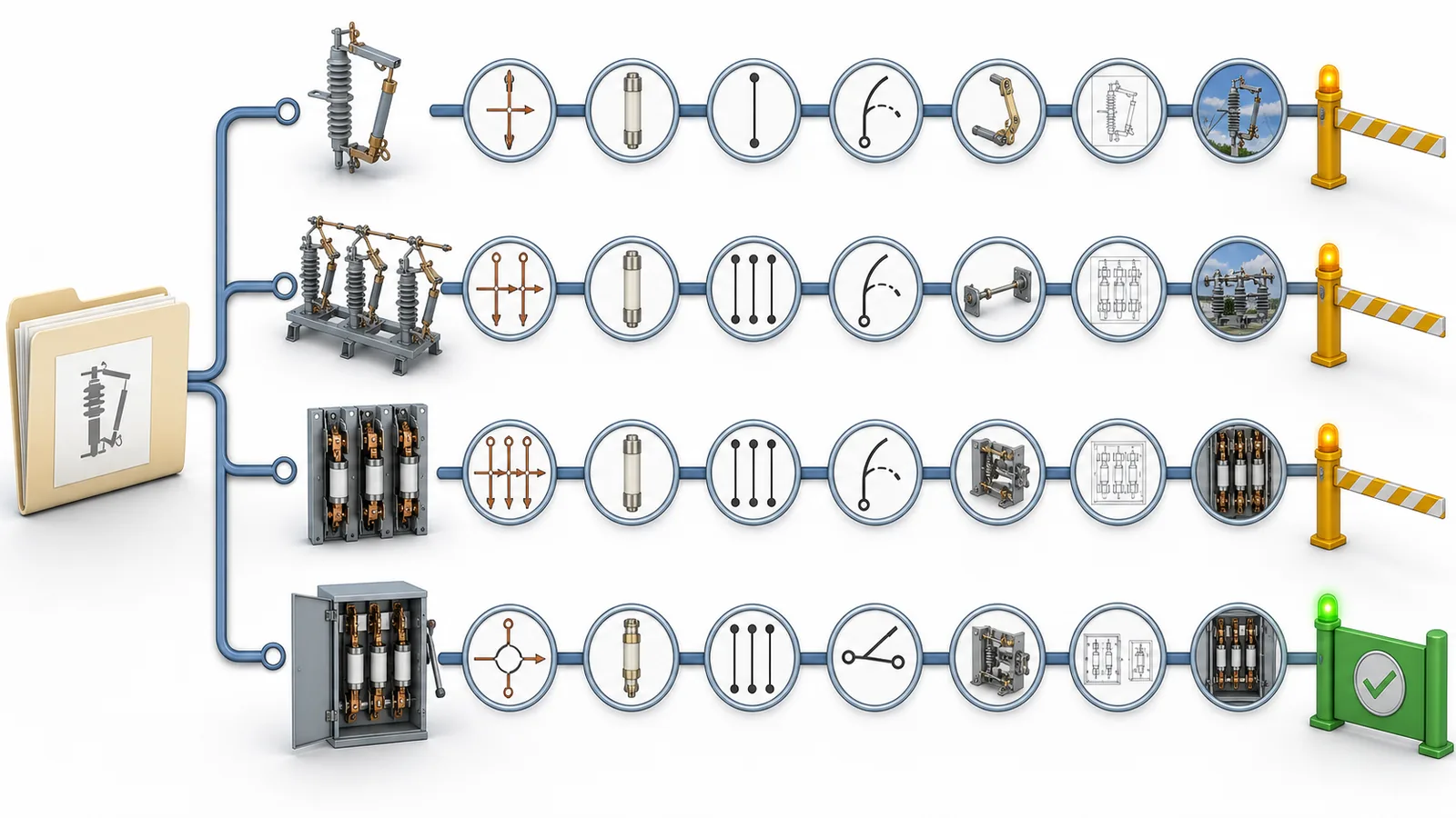
A three-pole switch-fuse combination is a candidate when a transformer feeder or enclosed distribution position needs declared three-pole normal switching plus current-limiting fuse protection in one functional assembly. The switch or switch-disconnector and fuses must be reviewed together, including the current path, fuse range, mechanism, interlocks, indication, and response after fuse operation.
The public page for IEC 62271-105:2021 covers three-pole functional assemblies for public and industrial distribution systems, composed of switches or switch-disconnectors and current-limiting fuses, above 1 kV up to and including 52 kV. It describes assemblies designed to make and break currents up to the combination’s rated short-circuit breaking current. The purchased standard, adopted edition, and project specification control clause-level requirements. This public scope does not cover expulsion fuse cutouts or prove that a product label complies.
Separate switch and fuse data sheets are necessary inputs but do not close the combination. The review must trace the fuse type and range to the switch, enclosure, mechanism, and tested or otherwise accepted configuration. Where the design uses a fuse striker or release, verify how fuse operation initiates switch opening, whether all poles open, required striker energy or interface limits, indication, and reset/replacement sequence at the equipment-selection level.
The release evidence index should identify the complete combination rating, switch duties, fuse range, short-circuit and coordination basis, applicable design/type evidence, mechanism and interlock drawing, routine/functional test plan, service conditions, deviations, reviewer, and disposition. It must not claim that documentation review independently proves performance in service.
Representative engineering review only. This is not a XIYA POWER customer, tender, utility, factory, test, commissioning, field, maintenance, outage, or service case. All values are illustrative and non-universal.
A 12 kV, 50 Hz radial project has three fused positions. Position A is a 200 kVA pole-mounted transformer lateral requiring phase-by-phase fuse protection and visible drop indication, with no remote three-pole switching requirement. Position B is an outdoor three-phase spur to a fenced distribution point requiring gang operation, a visible open point, and a replaceable fuse package. Position C is an indoor 1,000 kVA transformer feeder in an RMU requiring three-pole normal switching and a current-limiting fuse assembly, with a fuse-striker/release interface where the offered design uses one.
The first offer calls all three devices fuse disconnect switches. For A, no fuse-link or coordination return is supplied. For B, the offer does not identify expulsion versus HRC/current-limiting fuse technology, single-pole versus gang operation, or declared load-switching duty. For C, the supplier provides separate switch and fuse sheets but no configuration-applicable combination evidence or completed striker/release response.
Hold all three technical releases. A needs its cutout/link and coordination responsibility closed. B first needs its topology, pole operation, fuse technology, switching duty, and drawing defined. C needs complete-assembly evidence and a clear release-interface response. No installation or protection outcome is claimed; the example shows why one commercial label cannot close three different positions.
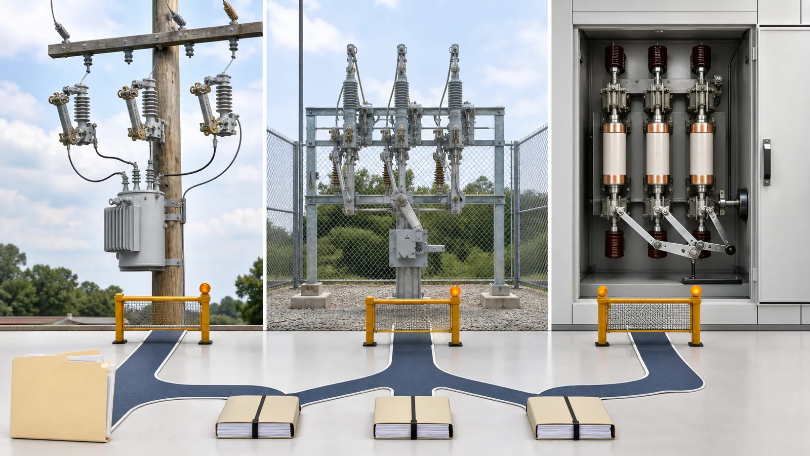
A drop-out fuse cutout is a defined pole-mounted topology with a hinged fuse tube and expulsion fuse link, typically applied phase by phase. A fuse disconnect switch is a broader commercial label whose fuse technology, pole operation, switching duty, mechanism, and physical arrangement must be identified.
Not necessarily. A switch-fuse combination here is a three-pole functional assembly of a switch or switch-disconnector and current-limiting fuses. A product sold as a fuse disconnect switch may or may not meet that topology, so the drawing and complete-assembly evidence control.
Only when the exact cutout and operating method have an applicable declared load-switching capability and the approved procedure permits the operation. Fuse fault interruption does not automatically grant manual normal-load switching duty.
Its making, switching, protective interruption, fuse range, mechanism, and release behavior depend on the integrated configuration. Separate component ratings do not prove how the offered switch and fuses function together.
No. A dropped tube or visible blade is one indication, not proof of isolation from all sources or absence of voltage. Authorized personnel must follow approved switching, isolation, test-for-dead, grounding, lockout/tagout, and permit-to-work procedures.
Include the one-line and position, voltage/frequency, phase operation, load-switching requirement, fault and coordination basis, fuse technology, complete-assembly duty, indication, release interface, service conditions, mounting and terminals, mechanism, drawings, deviations, manufacturer data, evidence, and approval owners.



