Quotation form
Send an inquiry
Start with the basics. Our team can follow up for missing drawings, standards or packing details.
Submitted details are used only for quotation, technical review and project communication.

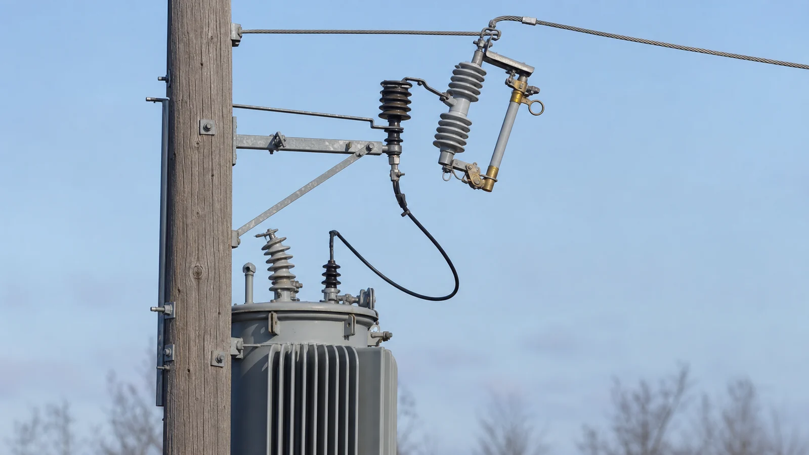
A drop-out fuse cutout is a pole-mounted, single-phase overcurrent protection device for medium-voltage overhead distribution networks. It combines a replaceable fuse link with a hinged fuse tube and a fixed cutout body to deliver three functions: fault and overload protection of branch circuits, automatic visual indication of a fuse operation, and manual isolation for maintenance switching. Understanding what the device does—and what it cannot do—is the starting point for any specification or replacement project.
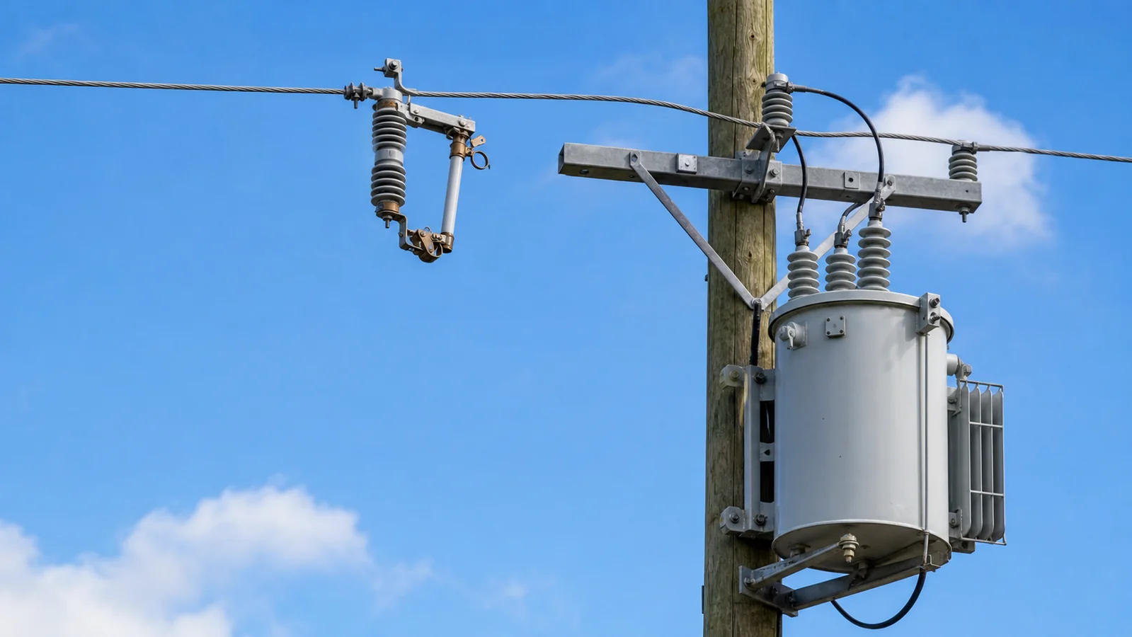
Drop-out fuse cutouts are applied at branch and tap positions, most commonly to protect distribution transformers and short lateral lines. Within that boundary, the device performs three operationally distinct functions that are frequently conflated.
Fault and overload protection. The fuse link melts when sustained current exceeds its rated time-current characteristic, interrupting fault current as defined by the selected assembly and the protection-coordination scheme. The intended outcome is to protect the transformer branch or lateral and limit the need for an upstream device to clear a downstream fault.
Visual indication. In many conventional cutout designs, a melted link releases the tube mechanism and the fuse tube rotates downward into an open position visible from ground level. This drop-open condition is a useful phase-specific indication of fuse operation; the exact release mechanism and indication arrangement are model-specific.
Manual isolation. An authorized lineman with an approved hot-stick tool can open or close the cutout to de-energize downstream equipment for planned switching, inspection, or fuse replacement. This is a controlled, sequential switching action—not an automated protection function.
These three functions share the same hardware but carry different operational implications. A drop-open tube signals that the fuse operated; it does not by itself constitute a confirmed safe working condition. Approved switching procedures, lockout/tagout protocols, and absence-of-voltage testing remain mandatory before any downstream conductors or transformer terminals are approached, regardless of tube position.
A drop-out fuse cutout is not a substitute for a distribution circuit breaker. It cannot provide feeder-level protection with adjustable trip settings, automatic reclosing, remote operation, or protection coordination via communication relays. Those duties require a dedicated breaker and relay assembly.
This is a planning aid, not a live-work instruction. Do not approach, test, replace, or operate equipment until the utility or site safety procedure has established the permitted condition of work.
| Symptom | First test or confirmation | Likely cause to review | Next action |
|---|---|---|---|
| Fuse tube is visibly open | Confirm system status through the approved operating procedure; do not treat the visible gap as proof of safe isolation | A fuse operation, or a manually opened device, depending on the operating record | Follow the approved isolation, test-for-dead, grounding, and protection-review procedure |
| New fuse link operates again after restoration | Review the protection study, protected load condition, and downstream circuit condition through authorized personnel | The original fault may remain, or the selected link may not coordinate with the application | Resolve the underlying condition before another restoration attempt and verify the approved assembly data |
| Contact or tube condition is uncertain after an operation | Inspect only under the approved maintenance procedure and use the manufacturer documentation as the acceptance source | Arc erosion, contamination, incompatible replacement parts, or mechanical damage | Replace or service the affected compatible component in line with the manufacturer and project requirements |
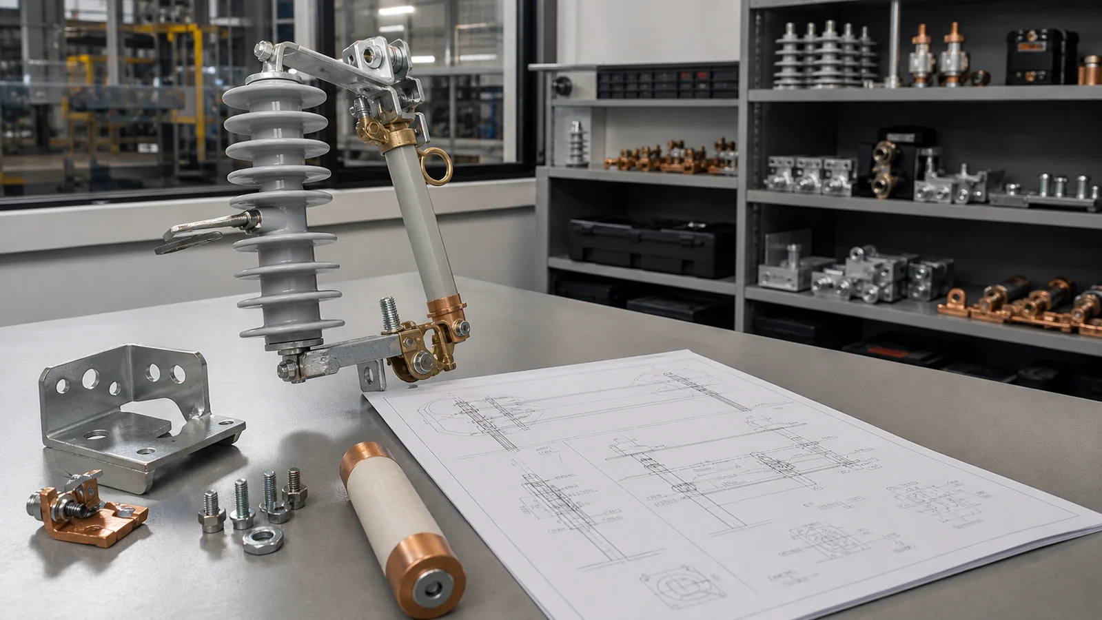
Three assemblies constitute a complete drop-out fuse cutout. They have different service roles and replacement considerations, so treating them as a single unspecified item causes stocking and maintenance errors.
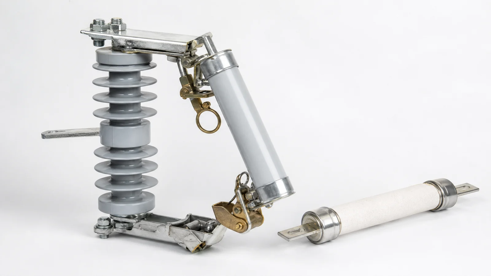
The cutout body is the permanent structure mounted on the crossarm or bracket. It includes the insulating porcelain or polymer housing, upper and lower contacts, mounting hardware, and conductor terminals. The body must be rated for line voltage, the required basic insulation level, and the mechanical load of the fuse tube assembly. The cutout body does not carry an interrupting rating in isolation—the rating always applies to the complete assembly of body, tube, and compatible fuse link.
The fuse tube is the hinged cylindrical carrier that holds the fuse link and seats into the cutout body contacts. In a conventional expulsion-fuse arrangement, the tube interior is lined with a material that generates de-ionizing gas during arcing. This gas blast quenches the arc and interrupts current at a current-zero crossing. In many conventional designs, the tube pivots on the lower hinge contact and drops to the open position under gravity when the link melts. Confirm the selected product’s operating arrangement before relying on a particular visible indication.
The tube must be mechanically matched to the cutout body and rated for the prospective fault current at the installation point. Tubes are inspected after each fault operation—arc damage to the liner or contact surfaces may require tube replacement before a new link is installed.
The fuse link is the sacrificial, replaceable element that carries normal load current and melts under fault or overload. Links are available in multiple time-current characteristic curves—commonly described as fast or slow, with specific designations varying by standard—to coordinate with upstream and downstream protective devices. The correct link type, current rating, and voltage rating come from the protection coordination study, not from the cutout body’s maximum current rating alone.
For context on the broader range of device families used on overhead networks, the distribution switching equipment category separates fuse protection from visible isolation, load switching, fault interruption, surge protection, and insulation support.
Under normal conditions, current flows through the cutout body contacts, tube contact surfaces, and fuse link in series. When a downstream fault or sustained overload occurs:
The drop-open position is an indication of fuse operation—not a guarantee of electrical isolation. Line-side voltage remains present at the upper contact of the open cutout. Safe isolation requires opening upstream switching devices, verifying absence of voltage with approved test equipment, and applying grounds per the applicable safety procedure before any downstream work begins.
When a planned switching operation is required—such as de-energizing a transformer for maintenance—an authorized lineman can open the cutout manually with a hot-stick, producing the same visible open-tube condition with the link still intact.
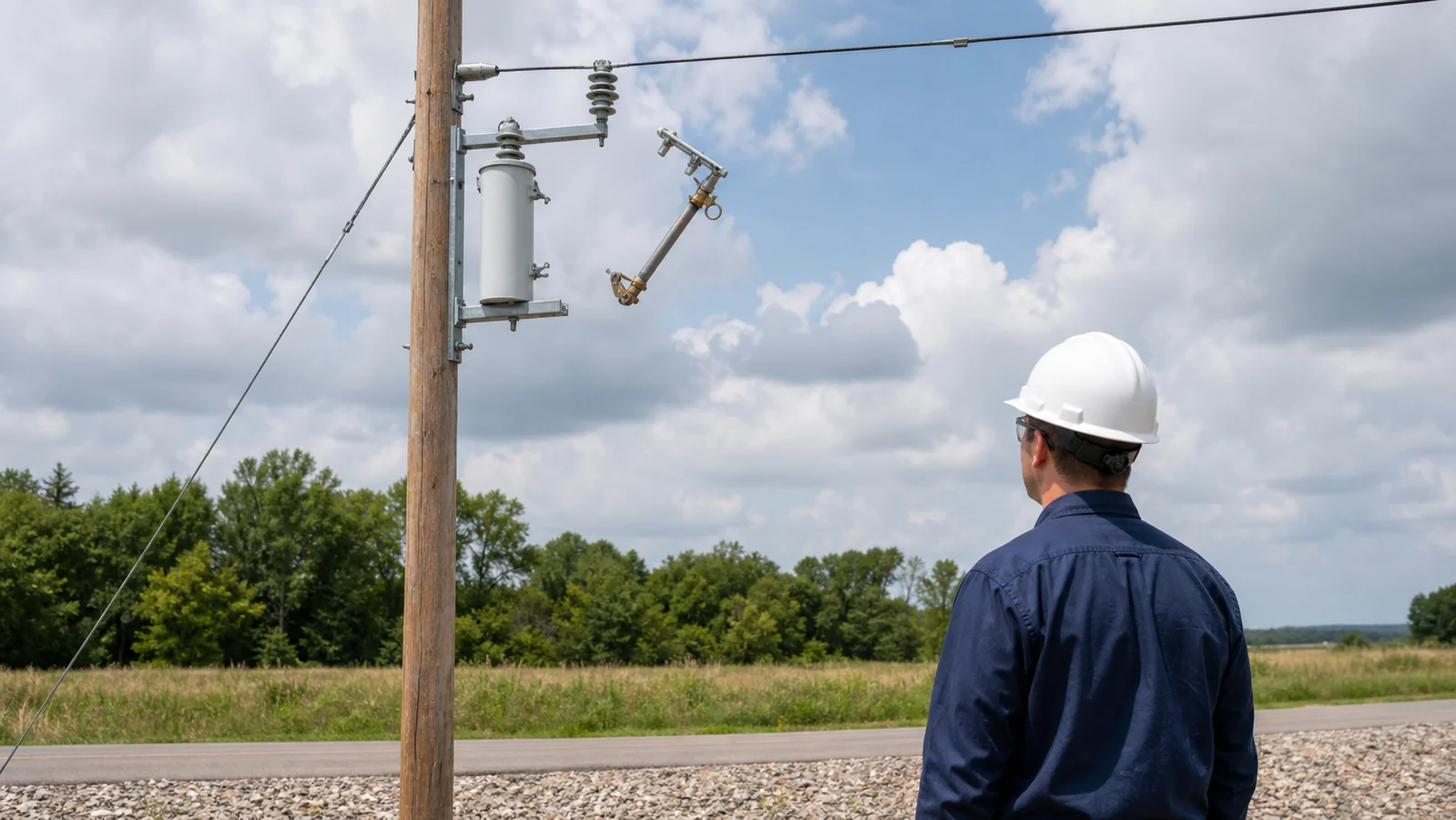
Drop-out fuse cutouts are well-suited to protecting:
They are not suited to replace:
Installations requiring protection against lightning impulses and switching surges typically mount surge arresters on the same pole structure adjacent to the cutout, because the cutout provides no overvoltage protection function.
Selecting a drop-out fuse cutout requires matching multiple parameters as a coordinated set. The table below identifies which parameters apply primarily to each assembly component.
| Parameter | Cutout Body | Fuse Tube | Fuse Link |
|---|---|---|---|
| Voltage class and BIL | System voltage and required BIL | Must match body voltage rating | Rated for same voltage class |
| Continuous current | Maximum rated current at ambient | Rated continuous current | Nominal rating (model-specific range) |
| Interrupting rating | Assembly-level symmetrical kA | Interrupting rating per standard | Link type and curve govern arc energy |
| Insulation / creepage | Pollution class and creepage distance | Not a primary parameter | Not applicable |
| Replacement interval | Long-life if not subjected to faults | Inspect after each fault; replace if damaged | Replace after every operation |
| Applicable standard | IEC 60282-2 or national equivalent | Per assembly standard | Per link class and curve specification |
This table shows why procurement requires all three components to be reviewed together. A body rated for a higher voltage may accommodate a lower-rated link only if all assembly parameters remain within limits set by the manufacturer for that specific combination.
Environmental inputs—altitude, ambient temperature, wind and ice loading, conductor tension, and pole hardware compatibility—must also be confirmed. High-altitude installations can affect both insulation coordination and the arc interruption behaviour of expulsion-type devices.
The XIYA POWER Drop-Out Fuses category separates standard cutout bodies, polymer and porcelain insulation options, higher-current rows, protected or enclosed constructions, windproof options, brackets, and fuse links. Use those as product-family starting points, then confirm the exact assembly rating, compatibility, and documentation for the project rather than carrying one row’s values into another.
For application-specific configurations, voltage class, continuous current range, interrupting rating, and creepage distance requirements should be verified against the utility specification and protection coordination study before finalizing a procurement request.
A drop-out fuse cutout is a passive, single-operation protection device for branch-circuit and transformer applications. It uses a replaceable fuse link for fault interruption and may be manually operated only in accordance with the applicable product instructions and site procedure. A circuit breaker is a recloseable, actively controlled device supporting repeated fault interruption, adjustable relay settings, remote operation, and communication-based protection coordination. They are complementary device classes designed for different duties and feeder positions, not substitutes for each other.
No. A drop-open tube confirms that the fuse link operated and the tube has moved to the open position, but line-side voltage remains present at the upper contact of the open cutout. Confirmed electrical isolation requires opening upstream switching devices in accordance with the applicable operating procedure, verifying absence of voltage with approved test equipment, and applying safety grounds before any personnel approach downstream conductors or equipment.
Fuse link selection depends on the protected transformer kVA rating, inrush current characteristic, maximum continuous load current, minimum and maximum fault current at the protected point, and required time-current coordination with upstream and downstream protective devices. A protection coordination study determines the appropriate link type—fast or slow—and current rating. The link must also be mechanically and electrically compatible with the specific fuse tube in use; these requirements are set by the manufacturer and the applicable standard.
After a fault causes the tube to drop, the tube should be removed and inspected for arc damage to the internal liner and contact surfaces before any reuse. A tube showing erosion or carbonization should be replaced, not simply refitted with a new link. The replacement fuse link must match the correct type and current rating. Cutout body contacts should also be checked for erosion or contamination. All work is carried out on a de-energized, grounded circuit per the applicable safety procedure.
Expulsion-type drop-out cutouts are normally selected for outdoor open-air overhead installation. Their interruption mechanism releases arc products and pressurized gas, so they must not be assumed suitable for an enclosed switchgear panel or indoor substation. Enclosed applications require equipment specifically rated and documented for that enclosure and environment, such as an appropriate current-limiting fuse or fuse-switch arrangement.
To prepare an accurate technical and commercial response, provide the following data when submitting a drop-out fuse cutout enquiry. Incomplete inputs extend review and specification confirmation time.
System and Site Data
Load and Protection Data
Mechanical and Installation Data
Quantity and Delivery
Submitting complete inputs at the RFQ stage avoids the most common delays: mismatched interrupting ratings, incorrect fuse link time-current curves, and creepage distance shortfalls that require order revision after initial review.



