Quotation form
Send an inquiry
Start with the basics. Our team can follow up for missing drawings, standards or packing details.
Submitted details are used only for quotation, technical review and project communication.

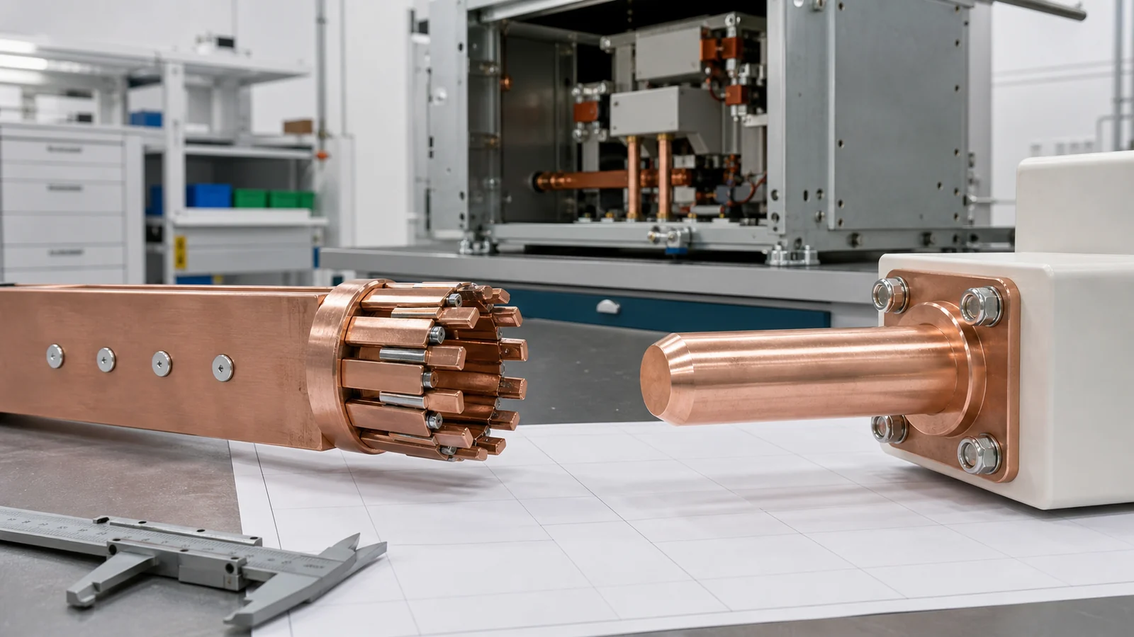
Switchgear contact arm tulip contact matching is a controlled interface decision, not a visual match. A replacement set is technically releasable only when the contact arm, tulip or finger assembly, fixed contact, mounting datums, engagement envelope, surface system, insulation interfaces, and complete-assembly duty all refer to the same approved configuration.
A shared breaker-family label or nominal diameter cannot prove interchangeability. The buyer needs a drawing-to-drawing comparison and an evidence package tied to the installed frame and revision.
Start by identifying the cabinet and breaker frame, drawout position, line/load side, phase, mechanism revision, contact-box or spout arrangement, and controlled drawings. The Switchgear Components pillar establishes the component family; the scheduled component acceptance checklist separately controls receiving identity, condition, traceability, and lot release.
Treat the three parts as one current-path interface set:
| Interface | Required input | What must agree | Release evidence | Hold condition |
|---|---|---|---|---|
| Identity and position | Cabinet/breaker family, side, phase and revisions | Every part belongs to the same controlled position | Drawing register and configuration record | Position or revision is unresolved |
| Contact arm | Body, length, offset, breaker mounting and insulation interface | Datums, centerline and connection geometry | Dimensioned arm drawing | Arm or mounting basis is inferred from appearance |
| Tulip/finger assembly | Arm-side retention, finger architecture and active bore zone | Retention to the arm and mating geometry to the fixed contact | Assembly drawing and material/surface declaration | Either interface is unconfirmed |
| Fixed contact | Active spigot, lead-in, working length, mounting and conductor interface | Insertion profile, contact zone, centerline and fixed-side mounting | Dimensioned fixed-contact drawing | Only nominal diameter is available |
| Surface system | Base materials, coating system, layers and coverage | Approved pairing of both working surfaces | Controlled specification and applicability record | Color or a generic certificate is the only evidence |
| Engagement and duty | Travel, stops, overlap, clearances and project duty | Complete set fits and is released for the offered assembly | Combined interface review and applicable evidence | Evidence belongs to another arrangement |
Missing input remains a hold item. It should not be filled with a catalog assumption or a dimension copied from another breaker generation.
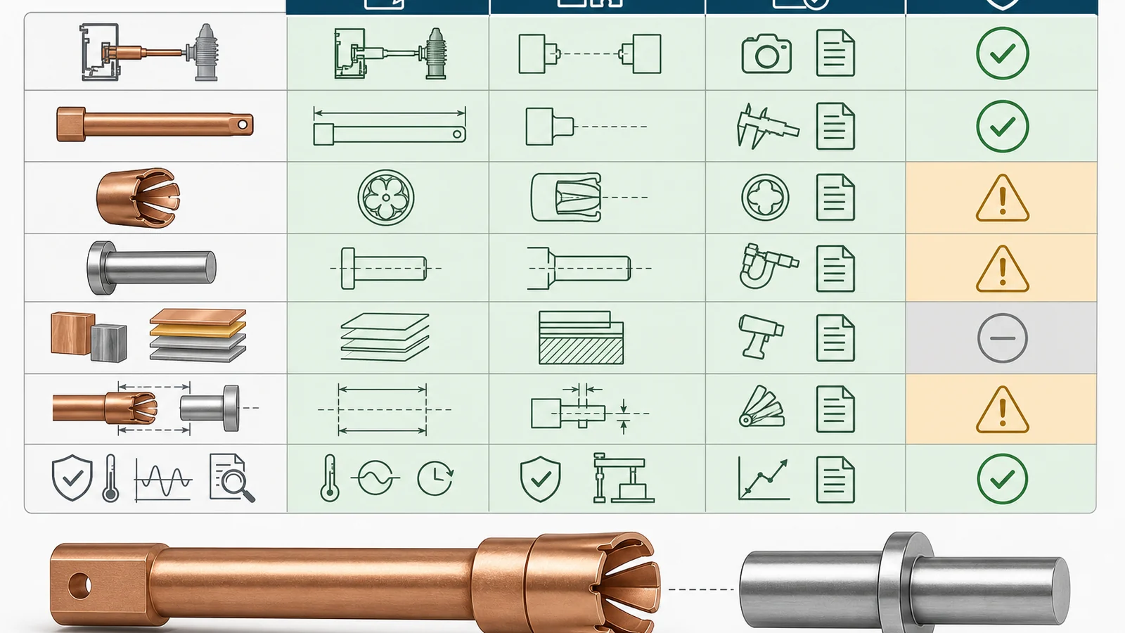
Normalize every drawing to the original design datums before comparing values. Measuring from convenient external edges can hide a centerline or axial error that becomes visible only after the breaker is racked into service position.
For the contact arm, compare overall current-path length, any axial or lateral offset, contact-end mounting, mechanism-side thread or hole pattern, shoulder/stop location, conductor interface, and the geometry passing through the insulating support. The copper contact arm product owner helps identify candidate forms, but its photos and type labels are orientation aids rather than interchangeability evidence.
For the tulip or finger assembly, record how it mounts to the contact arm, its retention feature, body and entry geometry, finger arrangement, spring architecture, active bore/contact zone, and the axial range over which the fingers are intended to work. The tulip has two different interface jobs: secure and conduct to the arm on one side, then accept the fixed-contact spigot through its working fingers on the other.
For the fixed contact, compare active spigot diameter at the controlled surface, lead-in profile, transition to the working zone, usable axial length, centerline, fixed-side thread or flange, shoulder, and bus/conductor connection. The fixed, tulip, and flat contact owner identifies these matching inputs and correctly keeps rating confirmation separate from drawing shape.
Nominal diameter alone omits where the diameter is controlled, whether it is a substrate or finished dimension, coating buildup, entry geometry, effective finger zone, and the overlap at the final mechanism position. The comparison must therefore show bare/finished condition where specified, common datums, tolerance ownership, and the installed relationship rather than three isolated part outlines.
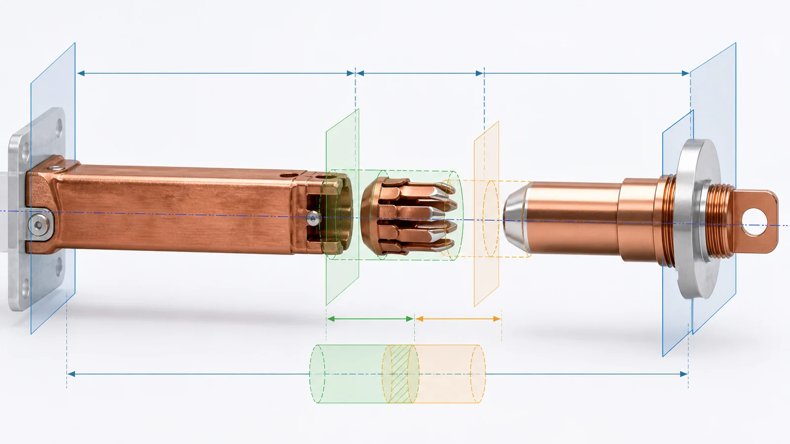
Material and plating are part of the matched interface, not generic quality labels. The controlled record should state the base material or alloy, coating material/system, layer sequence where required, specified coverage, masked areas, finish, lead-in treatment, and the approved pairing of the two working surfaces.
Silver-, tin-, nickel-, or copper-colored appearance does not establish the actual surface system. Nor does one certificate that names only the outer coating prove the underlayer, coverage, finished geometry, adhesion basis, or applicability to the opposite mating surface. Different coatings may form an approved pair in a particular design; identical-looking coatings may still belong to different specifications. Use the equipment manufacturer’s or approved project design basis rather than a universal same-coating rule.
Coating also interacts with dimensions. If the drawing controls the active diameter after plating, compare finished dimensions. If it controls substrate geometry and separately specifies buildup, the interface review must account for both surfaces without inventing a tolerance. Edges and lead-ins matter because an acceptable working surface can still be damaged by an incompatible entry profile.
This article controls the specified surface pairing before purchase. The scheduled contact assembly inspection guide owns received-condition assessment, pressure/spring evidence, installed alignment, plating acceptance, and contact-resistance evidence. Selection evidence and acceptance evidence should remain separate.
The correct loose parts can still form the wrong installed assembly. Overlay the breaker and cabinet drawings to confirm the insertion axis, first-contact position, working overlap, closed-position engagement, stop relationship, withdrawal path, and clearance through intermediate positions. Terms such as wipe or overtravel should follow the controlled equipment documentation; do not assign a universal value.
Check the arm centerline, tulip bore, and fixed-contact spigot against one datum system. Finger count, distribution, spring form, and retention influence how the tulip follows the spigot, but they do not prove pressure or current capability by themselves. A different architecture needs configuration-specific approval even when the nominal bore appears identical.
Also reconcile the insulating spout or contact box, seating depth, locating features, phase spacing, live-to-earth clearances, conductor connections, fastening interfaces, and maintenance/removal route. A dimensionally compatible metal set is not releasable if it shifts a live part outside the approved insulation or enclosure envelope.
Duty evidence should address the offered complete combination under the applicable equipment basis: normal current and thermal performance, short-time and peak duty, operating cycles, service conditions, and the particular switchgear or breaker standard. The public scope of IEC 62271-1:2017+AMD1:2021 covers common specifications for AC high-voltage switchgear and controlgear above 1,000 V, indoor or outdoor, up to 60 Hz, except where a relevant particular standard specifies otherwise. That public scope does not supply this set’s dimensions, ratings, tests, or release decision.
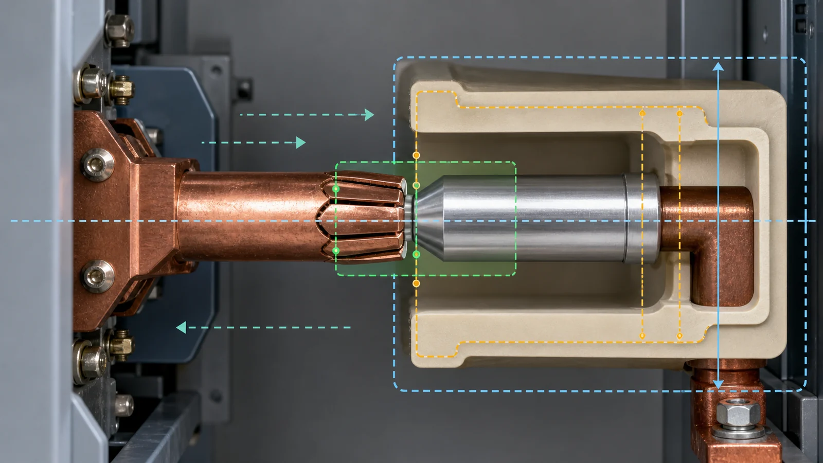
Shared controlled inputs:
Per-offer return package:
Keep manufacturer data, the project specification, controlled equipment drawings, and the short-circuit study or resulting duty basis as distinct evidence sources. Each source answers a different release question and must remain traceable to its revision.
Prefer a complete matched set when the retained parts cannot be traced to controlled revisions, the mating surface condition or geometry is uncertain, or the offered evidence applies only to an assembly rather than a loose component. A single-part offer can proceed only when every retained interface remains identifiable and approved.

Representative engineering review, not a XIYA POWER customer, factory, site, maintenance, commissioning, utility, or service record. The values below are illustrative and non-universal.
A 12 kV indoor drawout breaker requires a replacement tulip assembly and fixed contact. The offered parts carry a compatible-family label and resemble the installed set, but the controlled installed tulip is Drawing TCA Rev G while the offer is Rev D.
The illustrative drawing overlay shows that Rev D’s active finger zone ends 4 mm before the minimum working-zone boundary required by Rev G at the controlled closed position. The difference is a revision change, not a field-adjustment allowance. The offered fixed contact also has a different lead-in profile and a mounting thread that does not match the installed contact-box interface.
Both offered working surfaces are described as silver at the outer layer, but the certificate does not identify the required underlayer, finished coverage, or approved mating-pair specification. The accompanying duty record covers another frame arrangement and is not linked to this arm/tulip/fixed-contact combination.
Decision: hold technical release. Reconcile:
The family label and visual resemblance remain useful search clues, but neither closes any failed interface row.
No. The arm-to-tulip mounting/retention interface and the tulip-to-fixed-contact working interface have different jobs. Confirm their datums, mounting, active geometry, engagement range, surface system, mechanism position, and complete-assembly evidence. A shared nominal diameter is only one screening input.
Compare arm length/offset and mounting, tulip retention and active finger zone, fixed-contact spigot and lead-in, working overlap, centerlines, stop positions, threads or hole patterns, conductor connections, contact-box/spout interfaces, and finished dimensions where coating applies. Use one controlled datum system and drawing revisions.
Not necessarily. They must form an approved mating pair for the specific design and duty. Confirm base materials, layer systems, coverage, finished geometry, and the applicability record for both working surfaces. Do not infer compatibility from color or from a certificate covering only one part.
No. Such labels can identify a broad breaker or mechanism family, but they do not fix the frame configuration, drawing revision, arm offset, tulip retention, fixed-contact geometry, surface system, or duty evidence. Release against controlled drawings and the exact installed interface set.
Order or evaluate the complete set when retained parts lack traceable revisions, a mating surface or geometry is uncertain, the engagement relationship cannot be reconstructed, or evidence applies only to a specific assembly. A loose-part replacement is reasonable only when every retained interface stays controlled and approved.
Include cabinet/breaker identity, installed position, mechanism and drawing revisions, marked photos, arm/tulip/fixed-contact interfaces, controlled datums, surface-system basis, project duty and service conditions, applicable standards, and deviations. Require dimensioned drawings, an interface matrix, material/plating declarations, assembly applicability, duty evidence, and release status in return.