Quotation form
Send an inquiry
Start with the basics. Our team can follow up for missing drawings, standards or packing details.
Submitted details are used only for quotation, technical review and project communication.

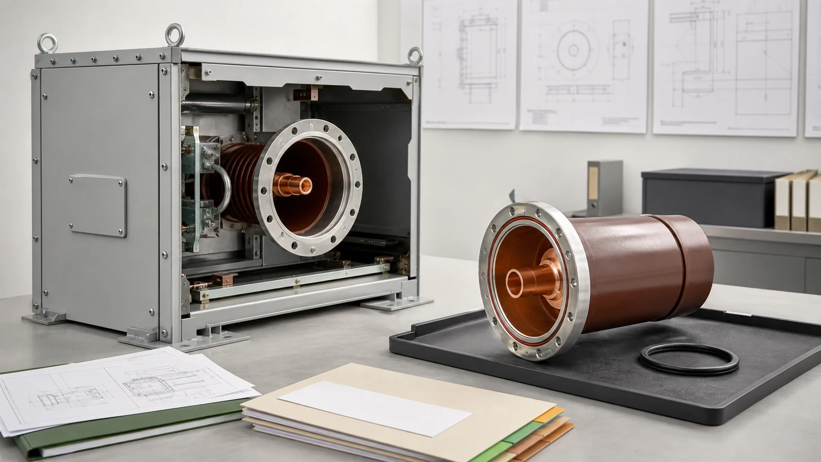
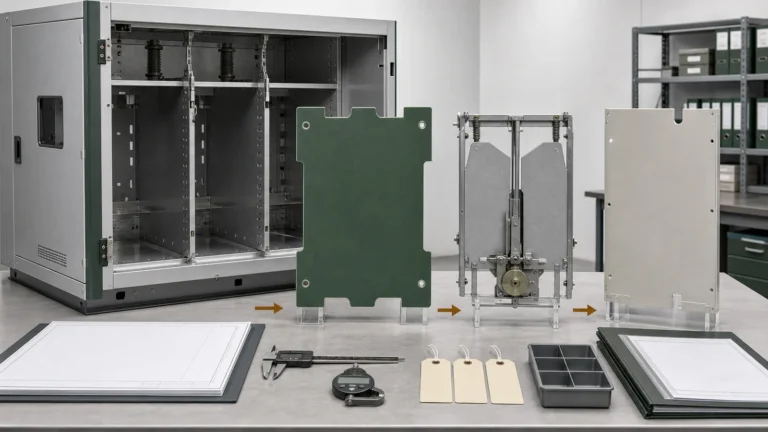
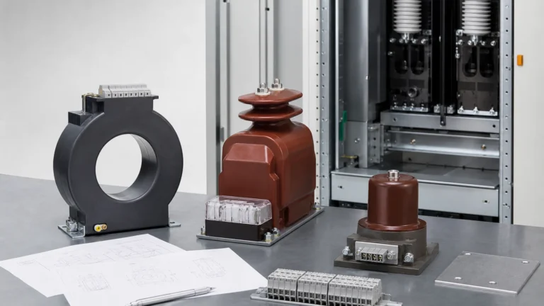
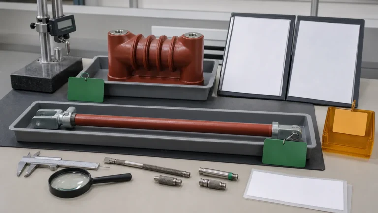
All images are generated illustrative technical visualizations, not XIYA POWER factory, product, order, drawing approval, manufacturing, inspection, measurement, assembly, sealing, filling, leak test, FAT, shipment, installation, commissioning, maintenance, failure, outage, or field photographs.
GIS sleeve accessory selection starts at the released cabinet interface and gas boundary, not at a product photo or voltage label. Map the cabinet datums to the candidate sleeve drawing, conductor geometry, sealing system, insulation evidence, and traceable records. A similar flange, molded profile, or generic seal material cannot establish interchangeability.
First identify the cabinet series, compartment, phase position, sleeve function, orientation, and gas-side boundary. Then freeze the cabinet drawing and project inputs that define that position. A removed part or model photo can support identification, but it cannot replace the approved interface.
The live GIS sleeve accessories page provides model photos and drawing views as matching aids. The Switchgear Components pillar places GIS sleeves in the primary-insulation and gas-cabinet connection zone. Both are starting points; technical release needs the complete component-to-cabinet chain.
Use this component selection matrix.
| Gate | Required input | Release evidence | Decision |
|---|---|---|---|
| Identity and position | Cabinet series, compartment, phase, function, orientation, change status | Approved cabinet drawing and controlled part identity | Position confirmed or hold |
| Geometry | Seating plane, pilot/bore, fixing pattern, orientation feature, envelope | Toleranced cabinet and sleeve drawings on common datums | Intervals compatible or hold |
| Conductor | Centerline, terminal planes, conductor form, joint and support boundary | Interface drawing and material/finish declaration where required | Current path reconciled or hold |
| Seal and insulation | Exact seal system, groove, medium, service conditions, insulation boundary | Applicable BOM, procedure, drawings, and configuration evidence | Boundary supported or hold |
| Records and release | Revisions, dimensional and compartment records, deviations, approvals | Reconciled data pack and signed interface-control sheet | Technical release or hold |
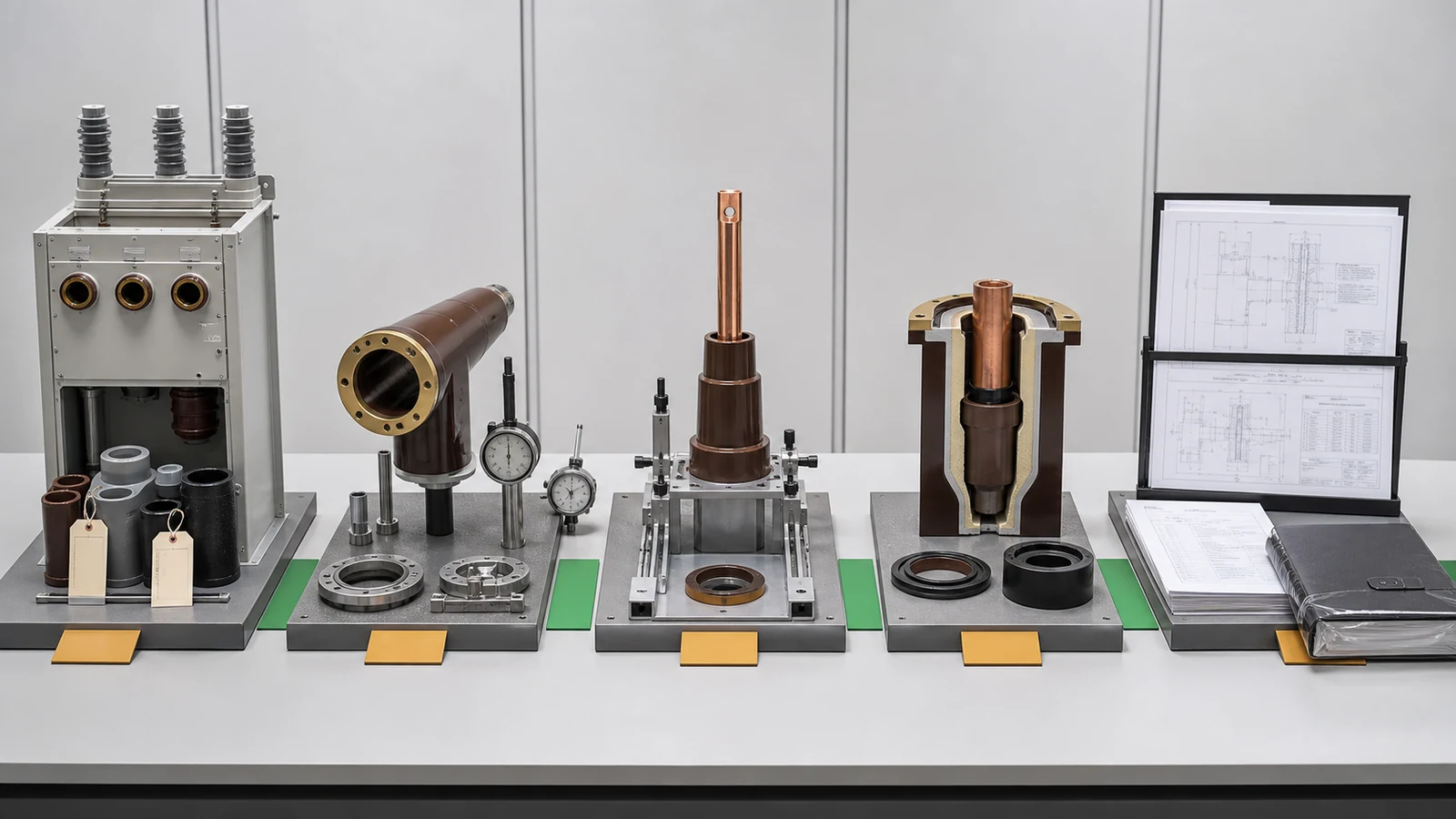
These are independent gates. A dimensional match cannot close a seal-record gap, and a generic certificate cannot establish the correct conductor terminal plane.
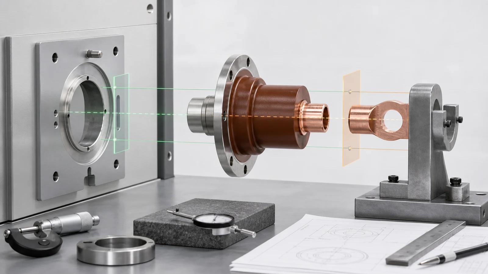
Compare dimensions from common datums. The cabinet side may define the compartment-wall seating plane, locating bore, fixing pattern, orientation feature, conductor centerline, and surrounding envelope. The sleeve drawing should define its seating face, pilot, holes or inserts, molded body, insertion depth, and terminal planes from those same references.
Nominal dimensions are insufficient. Record each interval, datum, geometric control where specified, and drawing revision. Confirm that the worst-case cabinet and sleeve limits permit the intended assembly without an unapproved change. A matching bolt circle can coexist with a wrong pilot, terminal plane, orientation, or external envelope.
Continue the datum chain into the conductor interface:
Do not infer plating, joint force, torque, or current-carrying acceptance values from a similar part. The project specification and manufacturer data must identify the applicable basis. A short-circuit study may define current-path duty, but it does not prove sleeve dimensions or fit.
The wall-bushing and contact-box selection guide owns its sibling cabinet datum chains, breaker travel, partition fit, and tolerance stacks. This article uses the same controlled-interface principle but does not treat those parts as GIS sleeve templates.
A gas-cabinet sleeve seal is a system, not a generic material label. Review the cabinet sealing face, sleeve groove, exact seal identity, compound compatibility with the approved insulating medium and service conditions, surface and cleanliness requirements, storage or lot traceability where required, compression load path, approved assembly procedure, and applicable tightness evidence together.
A return that says only FKM seal does not show the exact compound, part identity, approved groove, or procedure. The same material family can contain different compounds and application limits. The returned BOM should map the selected seal to the reviewed interface and procedure rather than asking the buyer to infer compatibility.
Do not copy universal values for O-ring squeeze, groove fill, surface finish, fastener torque, pressure, or leak rate. Those controls come from the approved seal-system design, component and cabinet drawings, manufacturer data, project specification, and applicable procedure. The selection review checks whether those sources reconcile; it does not redesign the seal.
| Seal-system element | Controlled source | Release question |
|---|---|---|
| Face and groove | Approved cabinet and sleeve drawings | Do geometry and revisions apply to the same interface? |
| Seal identity | Exact BOM and material/compound declaration | Is the selected part mapped to the approved medium and conditions? |
| Assembly boundary | Approved procedure and fastener/load-path definition | Is the procedure applicable to this configuration? |
| Records | Traceability, cleanliness, assembly, and tightness evidence where required | Do identities and revisions reconcile? |
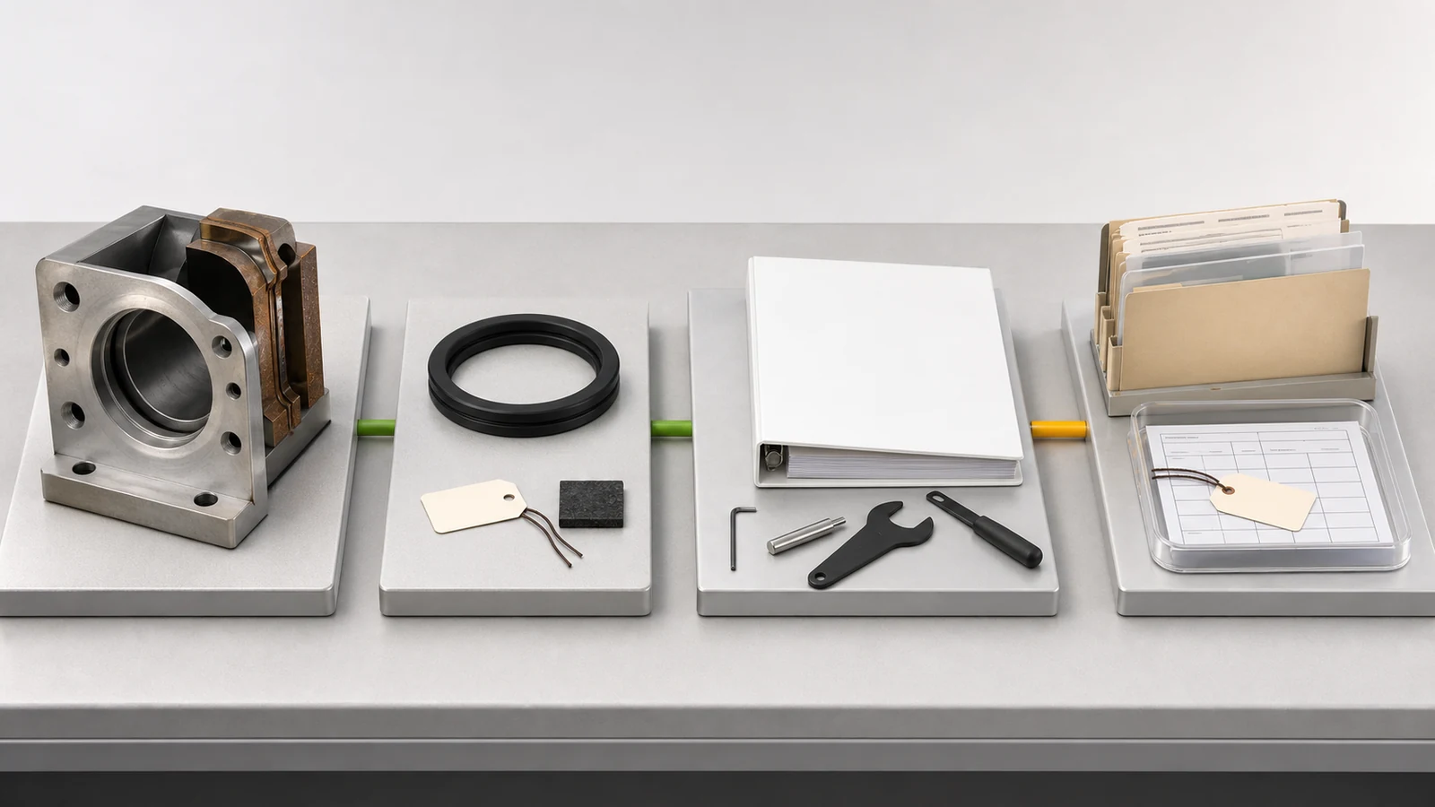
An absent record means the seal-system evidence is incomplete. It does not prove that a component leaked, that an activity was omitted, or that a generic material is unsuitable.
Consume the released cabinet voltage and insulation basis, exact compartment boundary, gas-side conductor and enclosure geometry, external-side profile, neighboring live and earthed parts, and field-control components where present. These inputs belong to the approved assembly, not to a standalone sleeve outline.
The GIS switchgear specification guide owns the complete cabinet design basis, insulating medium, service conditions, functional units, ratings, cable/civil/control/relief interfaces, and evidence schedule. COMP-09 begins after that basis is released and checks whether the component return maps to it.
A matching voltage class narrows the candidate field but does not prove compatibility. Gas-side profile, conductor-to-enclosure geometry, field-control arrangement, and applicable design or type evidence can differ between similar-looking sleeves. Resin color and outline are not insulation evidence.
The resin insulator and pull rod acceptance guide owns incoming-lot identity, sampling, molded-surface condition, dimensions, mechanical duty, and traceability for those resin parts. This selection review consumes applicable accepted records without repeating that receiving workflow.
The official IEC 62271-200:2021+AMD1:2024 CSV page identifies the publication as applying to prefabricated metal-enclosed AC switchgear and controlgear. Its stated range is above 1 kV and up to and including 52 kV, for indoor or outdoor installation. This is equipment-level scope only; it does not provide a sleeve drawing, seal design, conductor interface, tolerance, tightness method, interchangeability decision, or project release authority.
Define the return package before requesting a quotation.
RFQ checklist
Returned data pack checklist
Technical release checklist
This process gives procurement and engineering teams a repeatable decision without prescribing assembly or test procedures. The representative engineering review below applies it to a disclosed synthetic return.
Representative engineering review, entirely synthetic, illustrative, and non-universal. This is not a XIYA POWER customer, supplier, factory, product, order, drawing approval, manufacturing, inspection, measurement, assembly, sealing, filling, leak test, FAT, shipment, installation, commissioning, maintenance, failure, outage, or field case. No fit, tightness, insulation performance, compliance, acceptance, technical release, or result is claimed.
Synthetic interface inputs:
FKM seal.Synthetic returned document state: the sleeve tag is SL-07, while the candidate dimensional report references SL-70. A returned document titled as a tightness record identifies only cabinet family A and does not map to GS-04 or the reviewed interface revision. No approved conductor transition or change record is returned, and the final interface-control sheet is unsigned.
All values, identifiers, document titles, omissions, and hold states in this table are entirely synthetic. They do not show that a part was manufactured, measured, installed, assembled, sealed, filled, leak-tested, failed, accepted, or rejected.
| Gate | Synthetic observation | Decision |
|---|---|---|
| Dimensions | Cabinet bore interval 156.0-156.2 mm and candidate pilot interval 156.3-156.5 mm do not overlap | Hold geometry; require a reconciled drawing or authorized change record |
| Conductor interface | Cabinet terminal interval is 211.5-212.5 mm; candidate interval is 207.0-209.0 mm; no approved transition is returned | Hold current-path evidence; do not infer an actual fit outcome |
| Sealing | S-G2 does not reconcile with a generic FKM seal entry; exact part/compound, groove applicability, procedure, and traceability are absent |
Hold the seal-system evidence; do not infer material unsuitability or leakage |
| Records and release | SL-07 does not reconcile with SL-70; the candidate tightness document lacks configuration mapping; the interface sheet is unsigned | Hold records and release; do not infer that a measurement or test occurred |
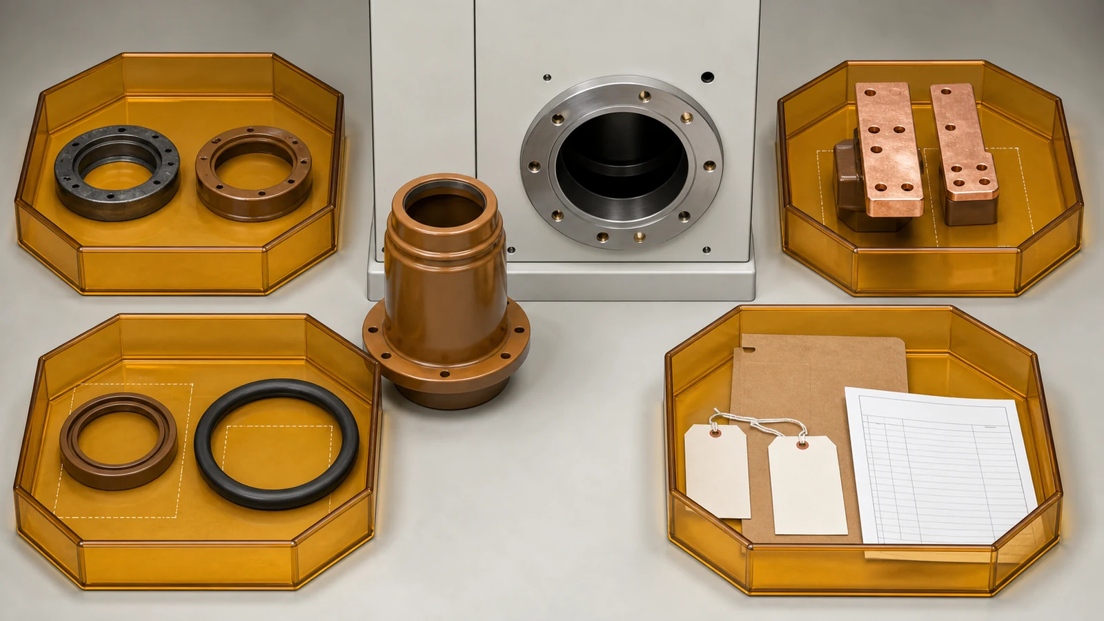
The four holds remain independent. A corrected dimensional report would not resolve the conductor or seal definition. A mapped tightness document would not sign the interface-control sheet. The synthetic return therefore cannot support a synthetic technical release decision as presented, without claiming any physical or test result.
Use the approved cabinet position and drawing, common datums and tolerance intervals, conductor form and terminal planes, exact seal-system reference, insulating medium and service conditions, insulation boundary, candidate sleeve drawing, applicable records, deviations, and named approval roles. All inputs should reconcile on one interface-control sheet.
Not from appearance alone. Similar parts can have different pilots, terminal planes, grooves, conductors, field-control profiles, materials, or applicable evidence. Interchangeability requires compatible drawings, tolerances, interfaces, records, and an authorized technical release.
Compare the seating face, locating bore or pilot, fixing pattern, orientation feature, molded envelope, conductor centerline, insertion depth, and terminal planes from common datums with full tolerance intervals. The approved design may identify additional controlled features.
Require the exact seal BOM and material or compound reference, groove applicability, approved procedure reference, and traceability, cleanliness, assembly, or tightness records where the project requires them. Each record should identify the reviewed part and interface revision. If a required record is not returned, mark the evidence incomplete; do not infer that the underlying activity did or did not occur.
No. Voltage class is one order-basis input. The actual insulation and fit decision also depends on conductor and enclosure geometry, gas-side profile, neighboring parts, field-control arrangement, seal system, and applicable configuration evidence.
Include the cabinet model and position, controlled drawings, common datums, tolerances, conductor interface, seal-system reference, insulating medium and service conditions, voltage and insulation basis, current-path duty source where relevant, replacement/change status, quantity, deviations, required records, and approval roles.