Quotation form
Send an inquiry
Start with the basics. Our team can follow up for missing drawings, standards or packing details.
Submitted details are used only for quotation, technical review and project communication.

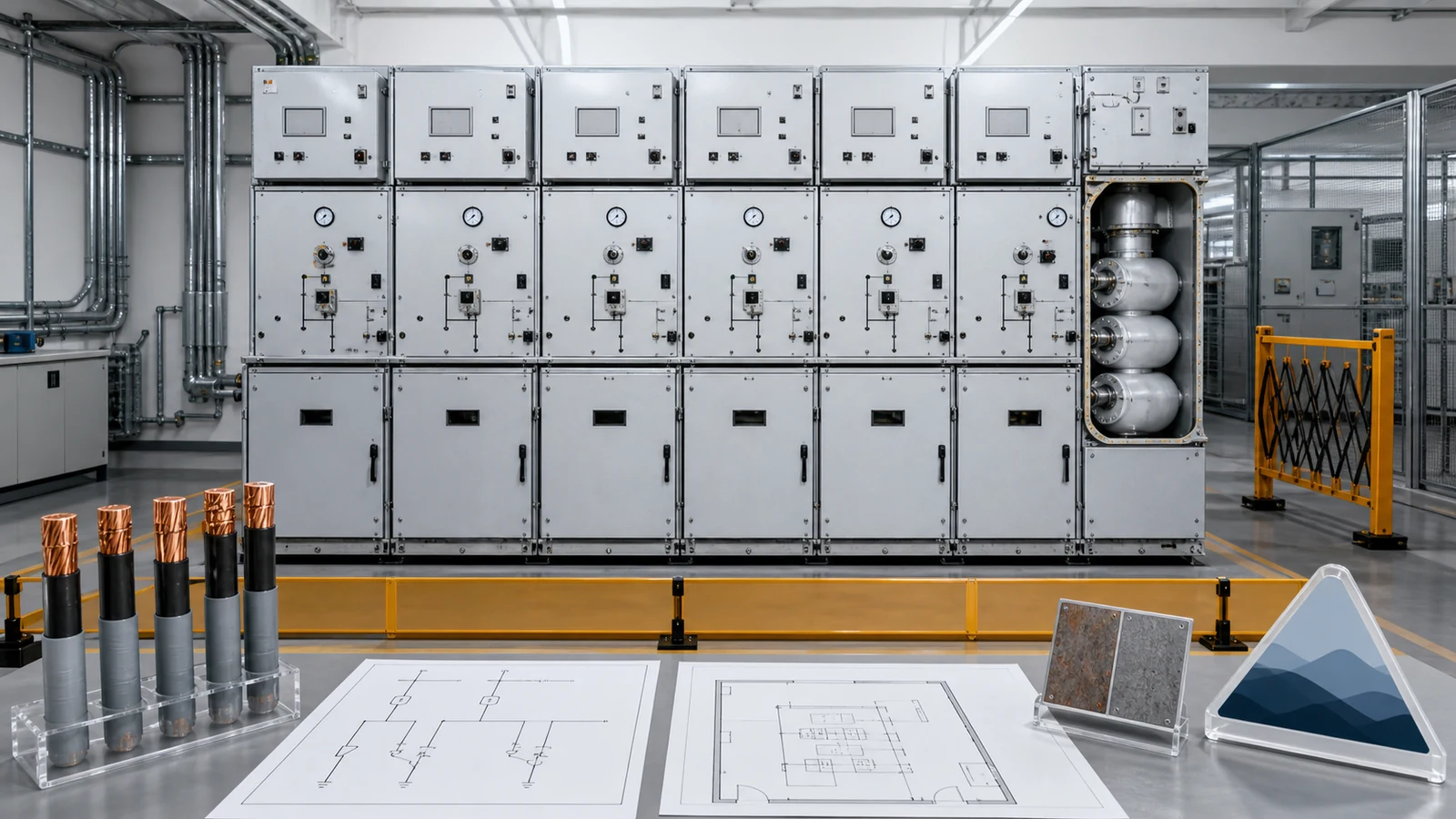
A GIS switchgear specification is complete only when the project design basis, exact insulation system, functional units, cable and civil interfaces, evidence, deviations, and approval owners all map to one offered assembly. A GIS name, sealed-tank description, or product-family maximum is not a technical release decision.
Visual disclosure: every image in this article is a generated illustrative technical visualization. It is not a XIYA POWER factory, customer, product-test, installation, commissioning, or field photograph.
Treat the specification as a controlled return schedule, not a catalogue request. The Complete Switchgear Cabinets pillar shows the wider cabinet taxonomy, while the AIS versus GIS foundation owns the earlier architecture decision. This guide starts after GIS has been selected and asks whether one offer fits one project.
Freeze the single-line diagram and operating states first. Identify incomers, ring cable ways, bus sections, couplers, protected feeders, metering, earthing functions, spares, and future extensions. Then state system nominal and highest voltage, frequency, earthing method, insulation basis, load and fault studies, normal and contingency currents, short-circuit duration, auxiliary supplies, and the adopted standard edition.
The same design basis must define the environment and every external interface. Without altitude, ambient, cable, room, control, communications, relief, transport, and approval data, suppliers will price different assumptions under similar GIS labels.
| Design layer | Purchaser input | Supplier return | Release evidence | Hold condition |
|---|---|---|---|---|
| System | SLD, bus states, voltage, frequency, earthing | Exact lineup and functional-unit schedule | Approved SLD and data sheet | Function or rating basis differs |
| Duty | Load flow, fault level and duration | Main/branch duties and device assignments | Study-to-offer matrix | Study revision or duty is unresolved |
| Site | Altitude, ambient, pollution, seismic and room conditions | Applicable service declaration and corrections | Configuration-specific statement | Generic normal-service assumption remains |
| Interfaces | Cable, earth, civil, control, SCADA and extension data | Drawings, envelopes, loads and point lists | Signed interface register | Any owner or dimension is open |
| Evidence | Required classifications, tests and documents | Applicability and deviation schedules | Accepted evidence register | A generic certificate substitutes for applicability |
Assign an origin, revision, return owner, reviewer, and approval state to each row. A value copied into a data sheet without its source revision can become wrong when the SLD or study changes.
Use the matrix as an RFQ checklist and controlled data pack: every required input must retain its source. Keep manufacturer data, the project specification, and the short-circuit study as independent evidence sources, then record where they agree or conflict before technical release.
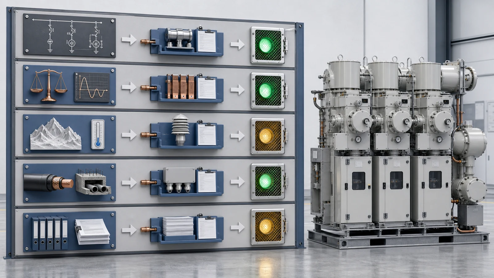
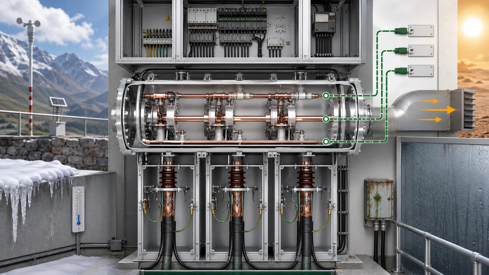
The live GIS Gas-Insulated Switchgear page is the commercial owner for available cabinet families. Project approval still requires site conditions rather than a generic normal-service assumption. Record altitude, ambient range, humidity and condensation, pollution, salinity or corrosion, dust, flooding risk, seismic duty, indoor or outdoor location, ventilation, access, transport restrictions, and the reserved extension boundary.
Require the offer to name the insulating medium and show its physical boundary. The return should identify common or segregated compartments, sealed-for-life or maintainable status as offered, compartment labels, monitoring contacts, reference density or pressure information where applicable, alarm wiring, relief direction, environmental documentation, and end-of-life responsibility. These declarations describe the selected system; they do not authorize filling, recovery, leak response, or maintenance work.
A sealed primary enclosure does not remove project interfaces. Cable terminations remain outside or at the insulation boundary. LV wiring, monitoring circuits, anti-condensation provisions, relief discharge, ventilation, access, and environmental records still need owners and approved drawings.
The public page for IEC 62271-200:2021 covers prefabricated AC metal-enclosed switchgear and controlgear above 1 kV through 52 kV, up to 60 Hz, for indoor or outdoor installation, including assemblies with air-insulated and/or fluid-filled compartments. Its public summary also identifies LSC, internal-arc, and earthing-circuit topics. The project must state the adopted edition, amendment status, required classifications, and applicable evidence; the public catalogue scope is not acceptance evidence.
| Site or insulation item | Required supplier return | Review question |
|---|---|---|
| Altitude and ambient | Correction or qualification basis for the offered assembly | Does it cover the stated site and current path? |
| Humidity, pollution and corrosion | Enclosure and material suitability declaration | Are external compartments and terminals included? |
| Insulating medium | Exact identity, boundary and environmental record | Is the declaration specific to this offer? |
| Monitoring and alarms | Contact functions, terminals and reference basis | Do they map to the control and SCADA lists? |
| Relief boundary | Direction and interface drawing | Is the path reconciled with the room design? |
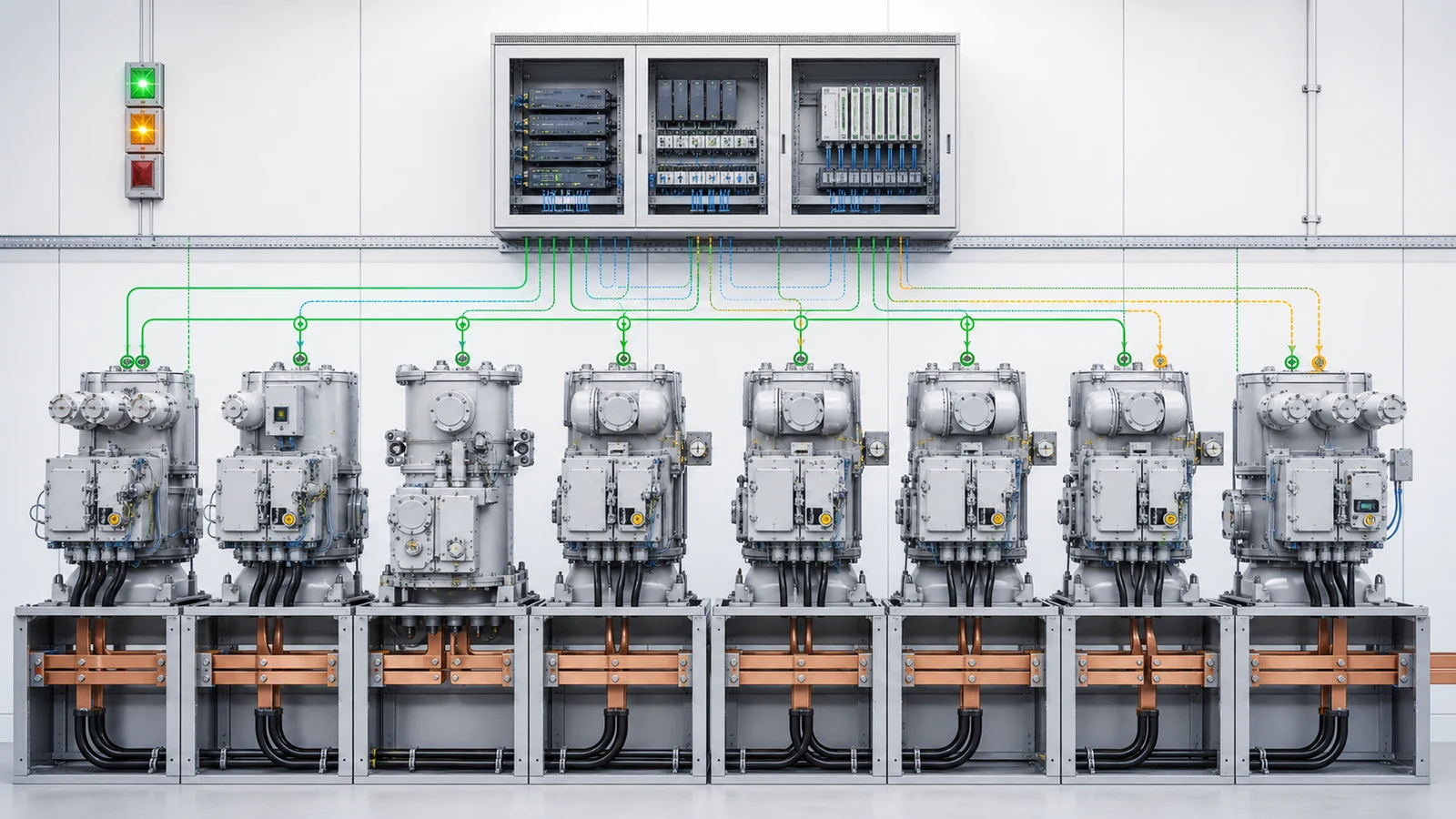
Build the lineup from the approved SLD, not from a convenient module string. For every position, record its network function, normal state, main and branch current, short-time and peak duty, switching or interruption owner, bus connection, cable interface, earthing function, measurement, protection, control, and communication scope.
The primary schedule should locate bus sections, cable ways, circuit breakers or other switching units, earthing switches, CTs, VTs or sensors, surge devices where required, and future joints. The secondary schedule should identify relays, meters, trip and close circuits, control supply, supervision, local/remote selection, indications, terminals, communications gateway, SCADA points, alarms, and interlocks. Do not fill missing project decisions with a universal CT ratio, relay function, protocol, control voltage, fuse selection, or switching sequence.
The RMU project specification demonstrates why each cabinet family needs its own interface schedule. Its feeder arrangement and protection choices are not defaults for this GIS lineup.
| Functional-unit field | Required declaration | Interface evidence |
|---|---|---|
| Network function | Incomer, ring way, section, protected feeder, metering or spare | SLD and module schedule agree |
| Primary duty | Current, making/breaking owner and withstand basis | Study-to-device schedule |
| Measurement/protection | Sensor locations and complete signal path | Schematics and device schedule |
| Control and interlocks | States, commands, permissives, loss-of-supply behavior | Interlock matrix and functional description |
| Automation | Points, protocols, terminals and responsibility boundary | Approved point list and wiring plan |
Review the complete signal chain. A density alarm contact is not integrated merely because it appears in a product data sheet: its contact function, terminal, control voltage interface, annunciation, SCADA tag, alarm owner, and test record all need to agree.
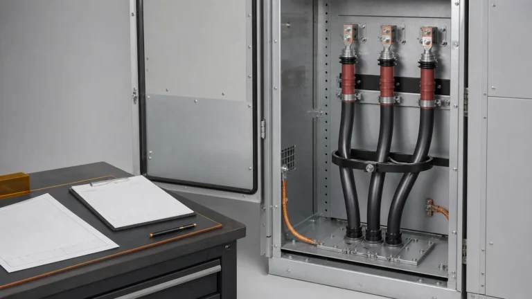
Cable fit requires more than conductor cross-section. Record cable type, conductor and insulation, quantity per phase, termination system, entry direction, gland or cleat arrangement, bending and working envelope, phase arrangement, screen earthing, and test access. The GIS supplier should return the termination chamber geometry and accepted interface; the cable or termination supplier should confirm compatibility against that exact drawing.
Close the surrounding installation at the same time. The main earth connection, floor opening, trench, base frame, anchors, section loads, lifting points, transport splits, access doors, LV cable entry, ventilation, relief path, and future bus extension must appear in an interface register. Pressure relief and internal-arc provisions are configuration-specific declarations tied to applicable evidence, not generic safety claims.
Use named ownership rather than a shared-action column. The purchaser or consultant supplies the design basis. The GIS supplier returns equipment envelopes, loads, connection points, and evidence. Cable and termination suppliers confirm fit. The civil designer closes foundations, trenches, room access, and relief interfaces. Protection and SCADA parties close secondary schedules. A named approval authority releases the coordinated drawings.
| Interface | Supplier return | Independent conflict check | Approval record |
|---|---|---|---|
| Cable termination | Chamber, phase and working envelopes | Cable schedule and termination fit | Purchaser plus cable party |
| Earthing | Main bar and screen-earth points | Project earthing design | Electrical approver |
| Foundation/trench | Base, loads, anchors and openings | Civil and structural model | Civil approver |
| Relief/room | Direction, connection and access envelope | Coordinated room layout | Building and electrical approvers |
| Extension | Bus-end condition and reserved work zone | Future layout and isolation plan | Purchaser authority |
Keep unresolved items visible as holds. Hiding them in drawing comments transfers risk to manufacturing or site work without resolving the interface.
A document can be supplied yet irrelevant to the offered configuration; it can be applicable yet still unapproved. Track supplied, configuration applicable, and approved as separate states. The KYN28 switchgear specification covers a different architecture, but uses the same discipline: exact configuration first, then interfaces, evidence, deviations, and approval.
The controlled return package should include the SLD; module schedule; general arrangement; foundation, trench, cable, and primary-connection drawings; insulation-system and compartment diagram; monitoring, alarm, and relief information; schematics; wiring and terminal plans; interlock matrix; protection and SCADA lists; labels; type-test applicability schedule; routine-test plan and records; FAT plan where required; manuals; spares; environmental and end-of-life records; packing plan; deviation register; and approval register.
For every cited type-test record, compare the tested assembly with the offered assembly. Record differences in ratings, functional units, compartments, insulating system, classifications, cable interfaces, or relief arrangement. A certificate title or family name does not close those gaps. The purchaser’s adopted standard and acceptance plan govern the decision.
| Gate | Required state | Release blocker |
|---|---|---|
| Design-basis gate | SLD, studies, site data and standards frozen | Conflicting inputs or revisions |
| Interface gate | Primary, secondary, cable, civil and relief records signed | Open owner or incompatible envelope |
| Evidence gate | Applicability schedule accepted | Generic or mismatched evidence |
| Deviation gate | Every deviation resolved or accepted | Undisclosed or open deviation |
| Drawing gate | Configuration-applicable drawings approved | Supplied-only status |

Representative engineering review, not a XIYA POWER customer, utility, factory, FAT, site, installation, commissioning, outage, or service case. All values are illustrative and non-universal.
The design basis states a 10 kV, 50 Hz resistance-earthed system and a 12 kV-class indoor GIS lineup at 1,800 m altitude, with -10 C to +40 C ambient, a 630 A main bus, 20 kA for 3 s short-time basis, and 110 V DC trip, close, and control supply. The preliminary SLD shows two ring cable ways, one bus-sectionalizing function, three VCB-protected outgoing feeders, and one metering function.
Available records are SLD revision B, a preliminary room layout, a load schedule, and a maximum fault-study result of 16.4 kA at the switchboard bus. The offer identifies a sealed common-tank arrangement and density alarm contacts. That is enough to start a review, not enough to release the assembly.
The GIS supplier still owes the insulating-medium declaration, altitude correction basis, compartment and relief drawing, alarm setpoint basis, cable termination envelope, SCADA point list, type-test applicability schedule, routine-test and FAT plans, environmental records, and deviation list. The consultant must reconcile the altitude and evidence basis; cable and civil parties must close the termination and room interfaces; the SCADA engineer must approve the points; and the purchaser must resolve deviations and witness requirements.
Technical release remains on hold until those returns are configuration applicable and approved. This example records a review decision only. It does not add cable sizes, relay settings, room dimensions, gas values, test results, approval, energization, performance, commissioning, or field outcomes.
Provide the approved SLD and bus states, voltage and frequency, earthing method, load and fault studies, insulation basis, service conditions, functional-unit schedule, primary and secondary interfaces, cable and civil data, adopted standards, required classifications, document register, evidence rules, deviations, and approval owners. The supplier should map each return to the exact offered assembly.
No. Altitude and ambient still affect the equipment declaration, while cable interfaces, external compartments, LV wiring, monitoring, relief, ventilation, corrosion exposure, transport, access, and environmental records remain project interfaces. A sealed primary system changes the boundary; it does not remove the boundary.
Declare the exact insulating medium, common or segregated compartments, sealed or maintainable status as offered, compartment identification, reference density or pressure information where applicable, monitoring and alarm contacts, relief direction, environmental documentation, and end-of-life responsibility. Handling procedures and maintenance limits belong in approved specialist documents.
Close cable construction, quantity per phase, termination, entry, bending and working envelope, screen earthing, test access, trench and floor openings, foundations, loads, anchors, access, LV entry, relief route, and extension space. Equipment, cable, civil, and electrical parties should sign the same coordinated interface record.
Use an applicability schedule that compares the tested and offered assemblies. Identify differences in ratings, functions, compartments, insulation system, classifications, cable interfaces, and relief arrangement. Resolve each gap through accepted evidence or a formal deviation under the adopted project standard; do not approve from a family name alone.
At offer stage, return a reconciled SLD, functional-unit schedule, preliminary general arrangement and interfaces, insulation-system declaration, compartment and relief concept, monitoring and alarm list, evidence-applicability schedule, and deviations. Before manufacture, complete the coordinated drawings, schematics, interlocks, terminals, SCADA list, test plans, environmental records, packing plan, and approval register.