Quotation form
Send an inquiry
Start with the basics. Our team can follow up for missing drawings, standards or packing details.
Submitted details are used only for quotation, technical review and project communication.

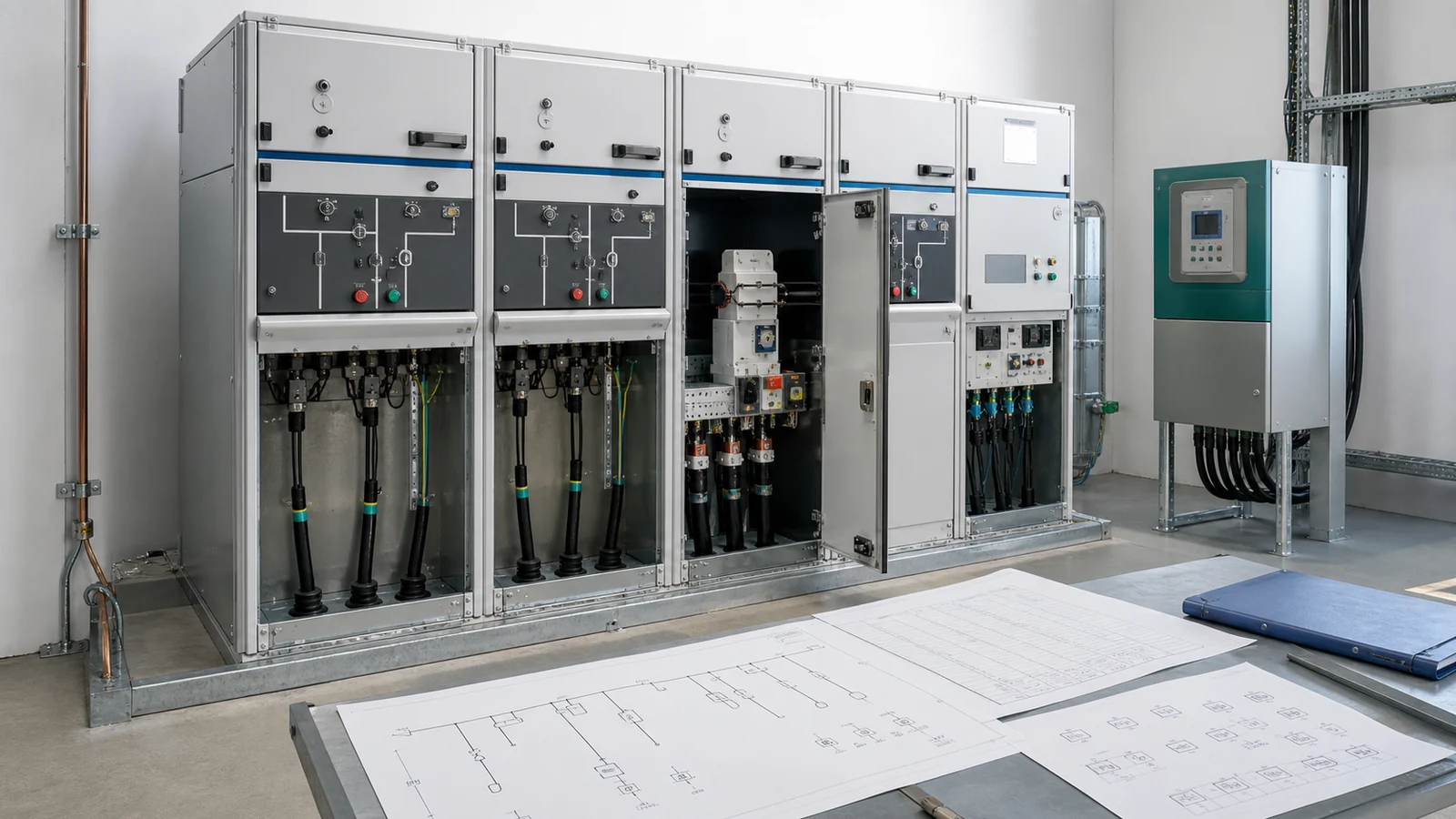
A ring main unit specification should freeze the network one-line and module duty schedule before listing cabinet ratings or model names. Each position needs a defined network role, normal state, switching or protection function, cable interface, isolation/earthing arrangement, control requirement, and release evidence.
The Complete Switchgear Cabinets pillar helps establish the cabinet family. The scheduled MV switchgear RFQ data guide owns the shared system inputs; this article converts them into an RMU-specific project package.
Do not begin from a catalog combination. Start from the controlled one-line, source directions, normal-open point, restoration philosophy, transformer or feeder circuits, ownership boundary, and future extension. Then build one selection matrix for the exact lineup.
| Position or network role | Normal state | Required function | Protection or isolation route | Cable and control interface | Release evidence | Hold condition |
|---|---|---|---|---|---|---|
| Ring incoming | Project-defined | Make/break stated normal current and isolate a cable section after suitable fault clearing | Switching, isolation and cable-side earthing functions as specified | Cable termination, indication and optional motor/remote interface | One-line, declared module duty and drawings | Source direction or normal state is unclear |
| Ring outgoing | Project-defined | Continue the ring, sectionalize, and support the approved restoration scheme | Same functions only where declared for the offered module | Cable, earthing, interlock and control interfaces | Network operating basis and module evidence | Normal-open point is unresolved |
| Transformer or feeder protection | Normally in service unless the scheme says otherwise | Clear the specified fault duty and coordinate with upstream/downstream protection | Fuse, switch-fuse, circuit breaker or other declared route | Cable, CT/VT/sensor, relay/controller and trip supply as applicable | Short-circuit and coordination studies plus configuration evidence | Protection route or coordination is open |
| Metering or sensing | Project-defined | Supply tariff, protection, indication or automation data | CT, VT or sensor route according to the measurement schedule | Secondary circuits, burden/interface and point ownership | Approved schedules and wiring | Measurement purpose or owner is missing |
| Tie, bus-section, spare or extension | Open, closed or de-energized as designed | Couple, sectionalize or reserve future functionality | Duty must be defined before equipment is selected | Bus, cable, civil and control provision | System study, GA and extensibility record | Future scope is only a note, not a defined interface |
The module schedule is a decision record, not a standard lineup. A missing required input remains a hold item; it should not be filled with a manufacturer’s default.
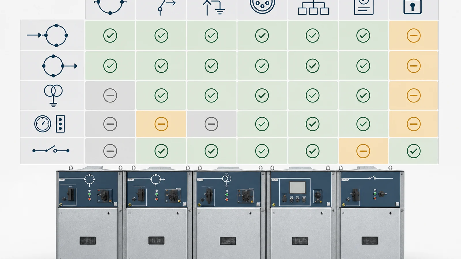
The published RMU foundation explains basic ring continuity and module functions. The scheduled RMU versus metal-clad comparison owns the architecture decision. CAB-03 starts after that decision and specifies the selected RMU.
Schedule ring ways, protected transformer or feeder positions, metering/sensing, bus-section or tie functions, earthing, and spare/extension positions from the one-line. Labels such as C, F, V, or CB are manufacturer-dependent shorthand; the declared function, ratings, interlocks, and offered drawings control. Do not translate one supplier’s module code directly into another supplier’s scope.
The live Ring Main Unit product owner presents several insulation and construction families. The project should state the required service, environmental, maintenance, and extension basis, then verify the offered insulation technology, common-tank or modular arrangement, bus system, access, pressure-relief route, and replaceable or sealed components against it.
Project-assigned LSC, partition, IAC, and accessibility requirements should appear as explicit schedule fields where applicable. They are not inferred from the term RMU, compact dimensions, or insulation medium. Detailed internal-arc selection remains a separate engineering task.
Control the arrangement by position identifier and drawing revision. For each position, cross-reference the one-line symbol, module function, tank or compartment, operating mechanism, cable side, earthing side, protection device, secondary terminal group, and interface drawing. When the lineup changes, review every dependent drawing and schedule rather than updating only the GA. A function count can remain unchanged while the cable side, bus connection, interlock, or secondary scope moves to another module.
Also state the maintenance concept expected by the project. Identify which compartments or sealed systems are not intended for site access, which components require inspection or replacement access, and how an extension or module replacement would be isolated from the in-service network. The manufacturer’s instructions and project operating rules determine the final method; the specification should ensure the proposed arrangement can support it.
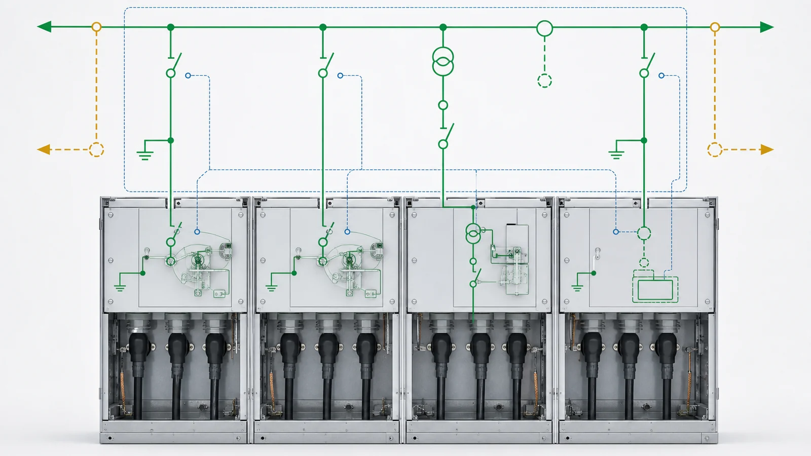
The public IEC 62271-200:2021 page applies to prefabricated metal-enclosed AC switchgear and controlgear assemblies above 1 kV and up to and including 52 kV, up to 60 Hz, for indoor and outdoor installation. It states that assemblies can include air-insulated and/or fluid-filled compartments. Its public change summary also identifies earthing-circuit, interlock, LSC, and IAC topics; it does not supply this project’s values or acceptance decision.
Build the RMU rating and protection schedule from the project specification and studies:
| Input group | Define | Verify in the offered lineup |
|---|---|---|
| System and service | Voltage/frequency/grounding basis, load schedule, service conditions and installation form | Complete-assembly ratings and service applicability |
| Fault and switching duty | Available fault basis, duration, normal switching, making, breaking and interrupting requirements | Exact module and complete-assembly declarations plus applicable evidence |
| Protection route | Transformer/feeder duty, fuse or breaker route, CT/VT/sensors, relay/controller, coordination and trip supply | Protection data, wiring and selectivity basis for the offered configuration |
| Isolation and earthing | Required isolating function, earthing locations, indication, operating permissions and site interface | Interlock matrix, mechanism drawings, earthing-circuit data and position indication |
| Assembly classification | Project-required LSC, partition, IAC, access and pressure-relief basis as applicable | Classification and type/design evidence applicable to the offered lineup |
Do not transfer a rating or report from another module, tank, insulation arrangement, number of functions, or revision without an applicability record. Interlock requirements should describe prohibited states and required interfaces; the approved equipment documentation and site rules govern the actual operating sequence.
Trace each protection decision through one evidence chain: project duty, study input, selected function, offered module, protection or fuse data, wiring and trip path, applicable design/type evidence, and final release record. Check that auxiliary-power loss, relay or controller failure, and local/remote selection have defined indications and project-approved behavior. The specification should request those records without inventing a universal relay function, setting, fuse size, or fail action.
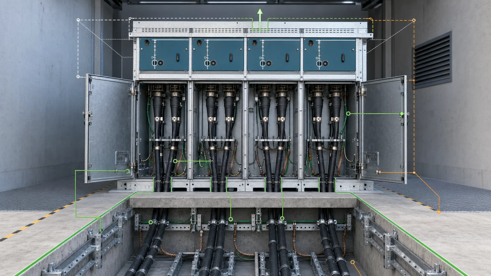
The RMU drawing and project cable/civil schedule must use one coordinate system and responsibility boundary. A correct electrical schedule can still fail if the offered cable compartment, base, or access arrangement does not fit the project.
Cable and civil interface checklist:
Require plan, elevation, base, termination-compartment, and interface drawings for the exact lineup. This page does not assign universal dimensions or cable sizes; CAB-08 will own detailed cable-routing design.
Motor operators, auxiliary contacts, a relay, or a communication socket do not prove automation readiness. Specify the complete control behavior and evidence package.
Shared RFQ checklist and project data pack:
Per-offer return:
Keep manufacturer data, the project specification, the short-circuit study, and the coordination study as distinct evidence sources. Technical release requires an accepted, configuration-specific package; a generic catalog or unrelated type-test report is not closure.
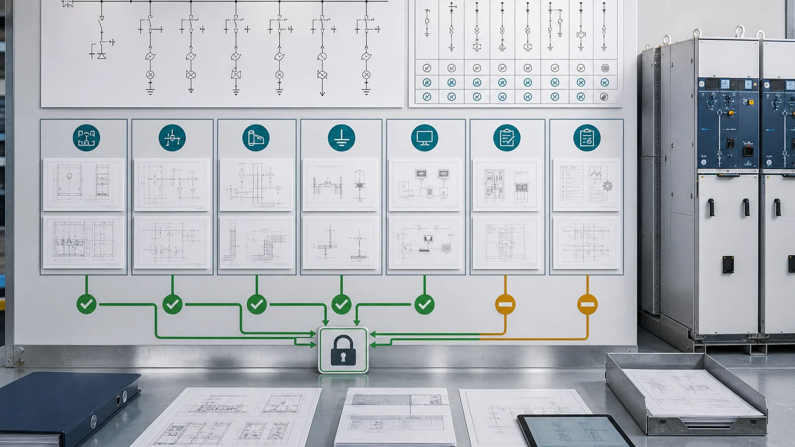
Representative engineering review, not a XIYA POWER customer project, factory case, site record, commissioned substation, utility installation, or service result.
A secondary-distribution project calls for two ring cable ways, one protected transformer feeder, metering/sensing, and remote indication. A supplier returns a three-function lineup, but the controlled one-line and normal-open point are not reconciled with the offer.
The transformer protection route remains open because the short-circuit and coordination bases are incomplete. Cable entry and termination interfaces are not aligned with the civil schedule. Screen earthing, cable-test access, the isolation/earthing interlock matrix, and pressure-relief interface have no shared responsibility record. Control power is named but not checked against the offered package; the point list and communication ownership remain drafts. Evidence applicability to the exact tank, module arrangement, and interfaces is also unresolved.
Decision: hold technical release. Reconcile:
No voltage, current, fault level, transformer power, cable size, module code, supplier, price, test, installation, commissioning, or service outcome is assigned. A project-specific review should begin with the controlled one-line, module schedule, studies, cable/civil interfaces, service conditions, automation requirements, and offered evidence.
Define the controlled one-line, source directions, normal-open point, position roles, and normal states first. Those decisions create the module duty schedule and determine the protection, cable, isolation, earthing, control, and evidence requirements.
Select it from the network one-line and project studies. Schedule each ring, protected feeder, metering/sensing, tie, earthing, spare, or extension position by declared function and interface. Do not use a default catalog combination or assume module codes are universal.
No. A module performs only the duties declared and evidenced for that exact design. Some positions provide normal-current switching and isolation after suitable fault clearing; protected positions may use a fuse, switch-fuse, breaker, or another declared route. Verify the complete assembly against the fault and coordination basis.
Provide cable quantity and construction, single/three-core arrangement, entry direction, phase order, termination and bushing/connector interface, screen earthing, test-access requirement, supports, base/trench coordinates, access, and responsibility boundaries.
Define motorized functions, auxiliary contacts, local/remote permissions, control power, sensing, relay/IED/RTU scope, point list, protocol/version, alarms/events, time synchronization, loss-of-power and loss-of-communication behavior, cybersecurity rules, and future provision as applicable.
Approve the one-line and module schedule, GA and interfaces, protection basis, coordination record, cable/civil drawings, interlock matrix, automation package, applicable evidence, inspection/FAT plan, document register, and deviations required by the project’s release gates. The exact hold points should be stated in the order documents.