Quotation form
Send an inquiry
Start with the basics. Our team can follow up for missing drawings, standards or packing details.
Submitted details are used only for quotation, technical review and project communication.

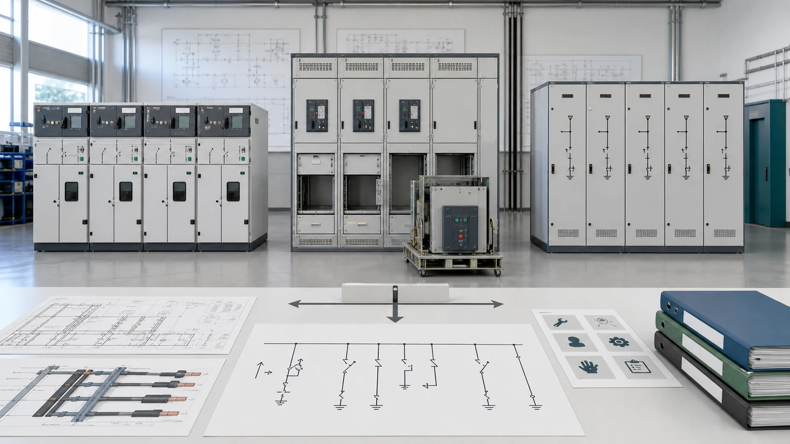
An RMU vs metal-clad switchgear comparison is useful only when the alternatives serve the same network functions and project requirements. RMU, metal-clad, and fixed-type describe different aspects of cabinet architecture; they are not three equivalent IEC classifications. Select the operating model first, then verify electrical duty, continuity, access, room interfaces, maintenance, expansion, controls, and evidence.
The Complete Switchgear Cabinets range shows the available product routes. A cabinet family should be released only after the project inputs below identify which route fits.
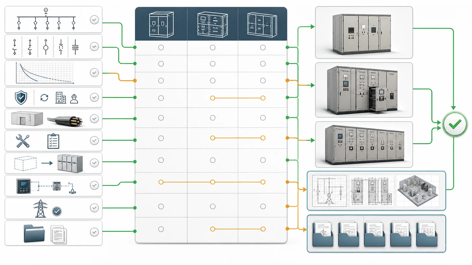
The selection matrix prevents a familiar label, compact footprint, or initial price from deciding the architecture too early. Every required input should lead to a decision, a defined supplier return, and release evidence. An unresolved input remains a hold condition.
| Architecture question | Required input | Decision affected | Release evidence | Hold condition |
|---|---|---|---|---|
| What must each bay do? | SLD, bay schedule, normal and contingency states, future bays | Functional units and switching devices | Approved SLD and bay schedule | Functions or devices are not frozen |
| What electrical duty applies? | System ratings, service conditions, short-circuit study | Assembly and device ratings | Study-linked rating schedule | Study revision or duty is unclear |
| What continuity and access model is required? | Operating scenario, accessible compartments, LSC, partition and IAC requirements where applicable | Compartment and access arrangement | Declared classification and applicable evidence | Commercial label is used instead of declarations |
| Does the cabinet fit the site? | Room plan, cable schedule, access, transport, foundation and pressure-relief route | Physical architecture and lineup arrangement | Coordinated GA and interface drawings | Room or cable data are missing |
| How will it be maintained and extended? | Planned tasks, outage boundary, spare strategy, future bays and extension direction | Fixed, withdrawable, or modular handling model | Maintenance and extension method | Lifecycle plan is undefined |
| What secondary scope is needed? | Protection, CT/VT or sensor, metering, control, interlock and communication schedules | Relay/control compartment and wiring scope | Secondary drawings and interface matrix | Ownership or interfaces remain open |
| Is the design acceptable and demonstrated? | Utility rules, project specification, deviation process and evidence requirements | Product eligibility and technical release | Compliance matrix and evidence register | Acceptance or evidence applicability is unconfirmed |
This sequence also exposes false equivalence. An RMU may contain load-switch, switch-fuse, or circuit-breaker functions. A product sold as metal-clad still needs declared compartment, partition, accessibility, and internal-arc characteristics. Fixed-type states how the main switching device is mounted; it does not define safety, reliability, or quality.
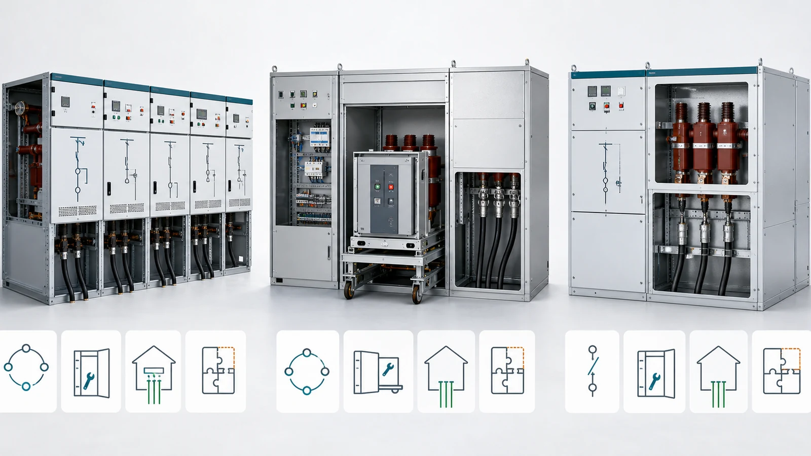
An RMU lineup is a compact functional architecture for cable-ring networks, secondary substations, switching stations, and branch or terminal points. It can combine load-switching, switch-fuse, vacuum-switching or circuit-breaker, earthing, metering, and automation modules. Gas, solid, and other insulation arrangements are possible, so RMU is not one insulation medium or protection tier.
The KYN28 metal-clad withdrawable route uses an indoor air-insulated, compartmented lineup with a withdrawable vacuum circuit-breaker truck, relay/control chamber, cable compartment, shutters, and interlocks. Service, test, and withdrawn positions support a defined handling model, but the offered assembly must still declare its actual LSC, partition, accessibility, IAC, rear-access, and interchangeability characteristics.
The XGN fixed-type route keeps the main switching device fixed within a metal-enclosed lineup. It can still use separated functional spaces, interlocks, earthing devices, and project-specific access arrangements. Fixed-type is a maintenance and handling choice, not evidence of lower safety or lower quality.
| Comparison point | RMU | Metal-clad withdrawable | Fixed-type |
|---|---|---|---|
| Typical application | Compact ring and secondary distribution | Indoor feeder, incoming, transformer and bus-section lineups | Indoor lineup accepting fixed-device handling |
| Functional units | Modular sequence; device varies by function | Panel bays, commonly with withdrawable VCB | Panel bays with fixed main device |
| Maintenance model | Depends on module and insulation design | Device truck can move to declared positions | Affected circuit is isolated for device access |
| Room implications | Compact, but cable and exhaust interfaces still govern | Operating aisle and truck movement must be coordinated | No truck movement; door and maintenance clearances still apply |
| Expansion | Confirm frame, bus and module extension method | Confirm end extension, bus and room growth | Confirm end extension, bus and room growth |
| Evidence focus | Module, insulation and assembly declarations | Assembly classification and truck configuration | Assembly classification and fixed-device access design |
No column is a universal winner. The SLD may favor compact modular functions while the maintenance philosophy favors a withdrawable device, or room and spare strategy may support a fixed arrangement. The complete input set resolves the trade-off.
The official IEC 62271-200:2021 page covers prefabricated AC metal-enclosed switchgear and controlgear above 1 kV through 52 kV, up to 60 Hz, for indoor or outdoor installation with air and/or fluid-filled compartments. It is currently presented with 2021+AMD1:2024 consolidated information, and the public revision summary notes LSC and internal-arc clarifications. The buyer must still state the adopted edition, national or utility rules, and project-specific declarations.
| Operator need | Project declaration | Design and evidence response | False shortcut | Hold condition |
|---|---|---|---|---|
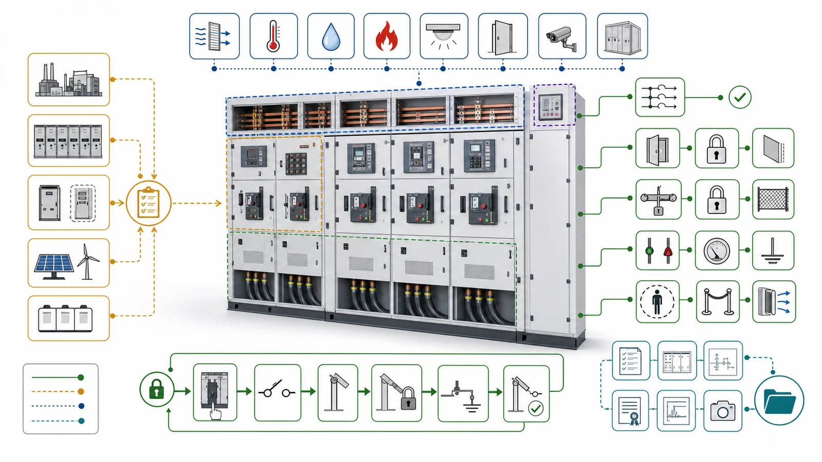
| Keep unaffected circuits supplied during access | Operating scenario, accessible compartment, LSC and partition requirements | Match the offered assembly declaration and applicable evidence | “Withdrawable means continuity” | Scenario or classification is not declared |
| Access secondary equipment | Required compartment and access condition | Confirm separation, interlocks and access rules | “Every metal-clad panel is identical” | Offered arrangement is not confirmed |
| Control internal-arc effects | IAC requirement, accessible sides, personnel and room/exhaust assumptions | Confirm configuration-specific classification and pressure-relief interface | “IAC tested” without configuration match | Scope or evidence applicability is unclear |
| Earth before access | Earthing method, isolation indication and interlock sequence | Confirm device capacity, logic and drawings | Assuming earthing is adequate by default | Earthing and interlocks are not reviewed |
Commercial names must therefore be translated into declared continuity, partition, accessibility, IAC, interlock, isolation, earthing, and pressure-relief requirements where applicable. Classification supports design verification; it never replaces the owner’s isolation, proving-dead, earthing, permit, and controlled-access procedures.
Physical and lifecycle constraints often decide between architectures that can all satisfy the SLD. Review each offer against the same room survey and operating plan.
| Room or operation question | RMU review | Metal-clad withdrawable review | Fixed-type review | Evidence or hold |
|---|---|---|---|---|
| Access and operating aisle | Confirm front, rear and side needs by module | Allow truck travel, door swing and panel access | Allow door swing and fixed-device access | Coordinated GA with access zones |
| Cable entry and termination | Confirm entries, quantity, bend and screen termination | Confirm each cable compartment and trench interface | Confirm each cable compartment and trench interface | Cable schedule and termination drawing |
| Transport and foundation | Confirm transport split, lifting and skid/frame | Confirm bay groups, lifting route and rails | Confirm bay groups, lifting route and rails | Transport and foundation plan |
| Pressure relief and ventilation | Confirm by module and insulation system | Confirm exhaust direction and room interface | Confirm exhaust direction and room interface | Pressure-relief path remains a hold |
| Planned maintenance | Define module access and replacement policy | Define truck handling, test facilities and spare truck | Define outage, fixed-device access and replacement | Maintenance procedure outline |
| Future extension | Confirm frame capacity and bus method | Reserve lineup end, bus and room growth | Reserve lineup end, bus and room growth | Approved extension drawing |
Also coordinate bus bridge or duct interfaces, equipment transport through doors and corridors, foundation tolerances, cable trench position, lifting access, cleaning policy, environmental controls, technician competence, and future outage boundary. A sealed or solid-insulated RMU does not mean no maintenance. A withdrawable breaker does not authorize live maintenance or guarantee faster restoration. A fixed device is not inherently difficult to maintain; its suitability depends on the planned tasks, isolation boundary, access, tools, spares, and owner procedures.
The detailed MV switchgear RFQ data checklist defines the wider input package. For architecture selection, normalize every offer to the same SLD, bay function, electrical duty, secondary scope, room interface, lifecycle boundary, and document package.
An RMU module, a withdrawable feeder panel, and a fixed feeder panel are not automatically equivalent. They can contain different protection devices, CT/VT or sensor arrangements, metering, cable provisions, automation interfaces, spares, tools, and documents. Footprint or price is not comparable until these boundaries align.
Use this bounded RFQ checklist before release:
Technical release requires one traceable configuration. A family brochure cannot close project duty, and a generic test record cannot confirm another internal arrangement, switching device, classification, or revision.
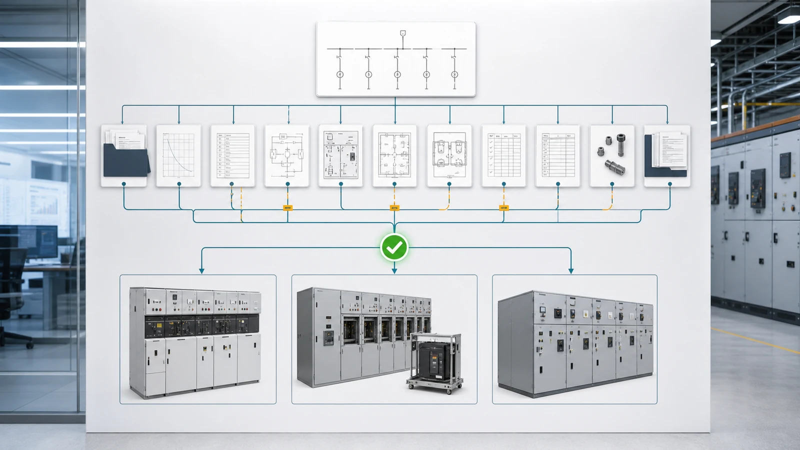
Representative engineering review, not a XIYA POWER customer project, factory case, field record, commissioned installation, or service result.
A buyer requests “compact metal-clad switchgear” for a cable-fed secondary substation. The SLD shows two ring-side cable functions and one transformer feeder, but the switching and protection device in each unit is not frozen. The room constrains footprint and rear access; cable termination, pressure relief, transport, and future extension remain unresolved. The buyer expects continuity during maintenance but has not declared the operating scenario, accessible compartment, LSC, partition, or spare strategy.
Three offers arrive: modular RMU functions, a withdrawable metal-clad lineup, and a fixed-type lineup. Their protection packages, access assumptions, evidence, and functional scope differ, so neither footprint nor price is yet comparable.
Decision: hold architecture selection. Reconcile the package in this order:
No architecture, saving, dimension, outage result, safety result, or commissioning outcome is invented. Release the decision only when the same functional and evidence boundary applies to all offers. For review, provide the SLD, bay schedule, ratings and studies, continuity/access philosophy, room and cable data, maintenance and expansion plans, automation interfaces, evidence requirements, quantity, destination, and deviations.
No. RMU describes a compact functional architecture for ring and secondary distribution. Metal-clad is a commercial description for a compartmented arrangement that must be translated into the offered assembly’s actual declarations. They are not equivalent classification terms.
Yes. An RMU can include load-switch, switch-fuse, vacuum-switching, or circuit-breaker modules. The bay function and protection duty determine the required device.
No. A withdrawable device supports defined service, test, and withdrawn positions, but continuity depends on the operating scenario, accessible compartment, LSC, partition, interlocks, and offered assembly evidence.
No. Fixed-type describes device mounting and maintenance access. Safety depends on the complete compartment design, interlocks, earthing, classification, procedures, and evidence, not withdrawal alone.
Use the SLD and bay functions, electrical and short-circuit duty, continuity/access philosophy, room and cable interfaces, maintenance and spare strategy, expansion, protection and automation scope, utility acceptance, and evidence requirements.
Compare configuration-specific manufacturer data, coordinated drawings, applicable design/type evidence, the project specification and short-circuit study, routine/FAT plans, deviations, utility acceptance, spares, handling scope, and controlled final documents.