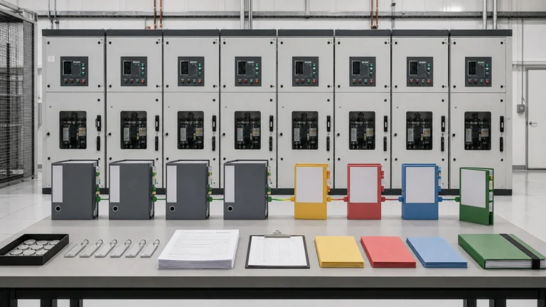
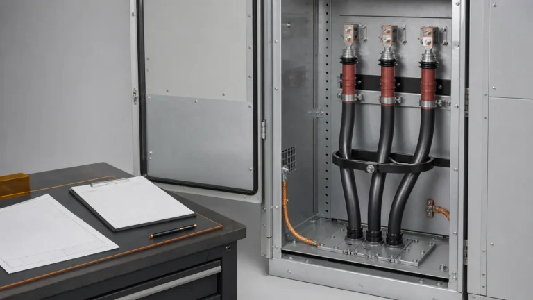
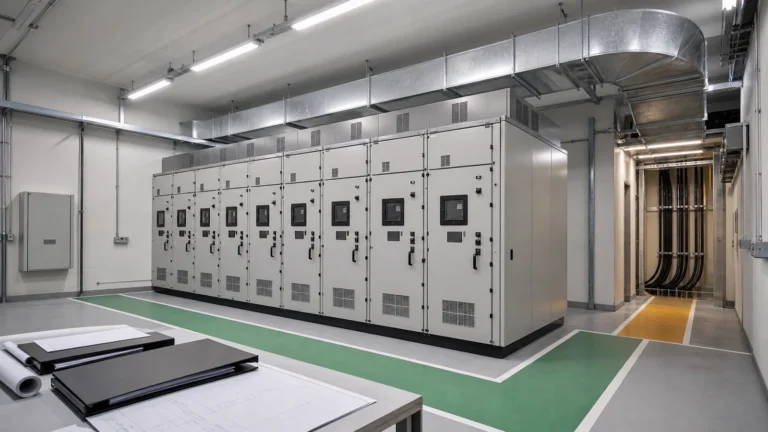
Quotation form
Send an inquiry
Start with the basics. Our team can follow up for missing drawings, standards or packing details.
Submitted details are used only for quotation, technical review and project communication.

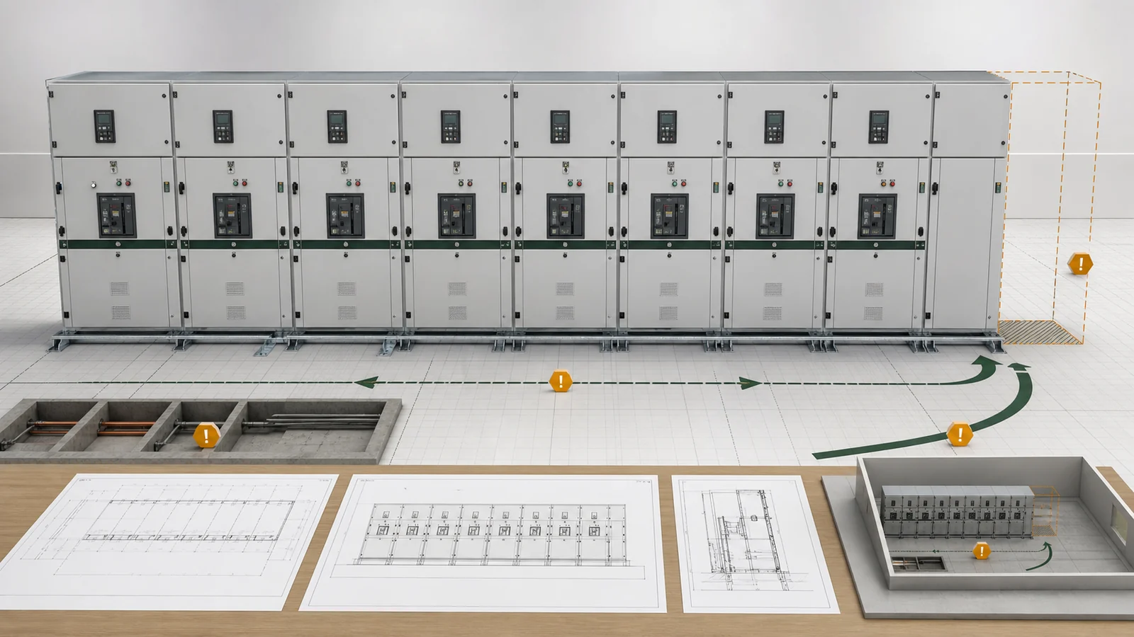
All images in this article are generated illustrative technical visualizations, not XIYA POWER factory, cabinet, civil-work, trench, installation, commissioning, or field photographs.
By Candy Zhao, Sales Director, XIYA POWER.
A switchgear general arrangement drawing review is complete only when one coordinate system connects the bay schedule and equipment envelope to the room grid, access and handling swept volumes, foundation details, trench interfaces, and future extension provisions. A plan view or approval stamp alone is not enough. Each interface needs a controlled input, owner, decision, evidence source, hold condition, and separate release record. This guide covers initial physical and civil coordination; it does not replace the short-circuit study, detailed cable-termination review, drawing-revision workflow, or an authorized release for manufacture or civil work.
A GA package is an interface model, not one picture. Use this selection matrix near the start of the review so a missing record remains visible instead of being absorbed into a general drawing approval.
| Gate | Required input | Review decision | Release evidence | Hold condition |
|---|---|---|---|---|
| Source and coordinates | Current bay schedule, room grid, finished-floor datum, equipment datum, drawing revision/status | Do all views and source records use the same technical state and origin? | Drawing register plus marked coordinate comparison | Revision, datum, or bay-schedule mismatch |
| Envelope and sequence | Overall dimensions, bay widths, end panels, protrusions, transport splits | Does the complete lineup fit and match the intended bay order? | Dimension reconciliation and transport-split return | Room conflict, omitted projection, or sequence mismatch |
| Access and handling | Door/shutter sweeps, withdrawable-unit path, panel-removal route, lifting/rolling route, escape path | Are the moving volumes usable in operation and replacement states? | Swept-volume overlay against the room plan | Any unresolved structural, service, or route obstruction |
| Civil and trench | Base/rail/plinth, anchor zones, floor-loading source, trench/opening coordinates, floor level | Do equipment and civil records share one datum and responsibility boundary? | Approved civil drawing plus manufacturer base detail | Coordinate mismatch or unassigned interface owner |
| Extension and release | Extension direction, reserved bay width, end condition, bus/earth continuation concept, temporary closure | Is future space physically protected and supported by evidence? | Reserved-zone drawing and supplier extension return | Conflict, missing end detail, or missing continuation concept |
IEC 61936-1:2021 provides the broad design-and-erection context for electrical power installations above 1 kV AC. Its public page does not provide project-specific aisle widths, door sizes, trench dimensions, anchor coordinates, foundation tolerances, or extension-space criteria. Actual values and acceptance sources must come from the project specification, applicable local requirements, approved civil drawings, manufacturer data, and the responsible engineer.
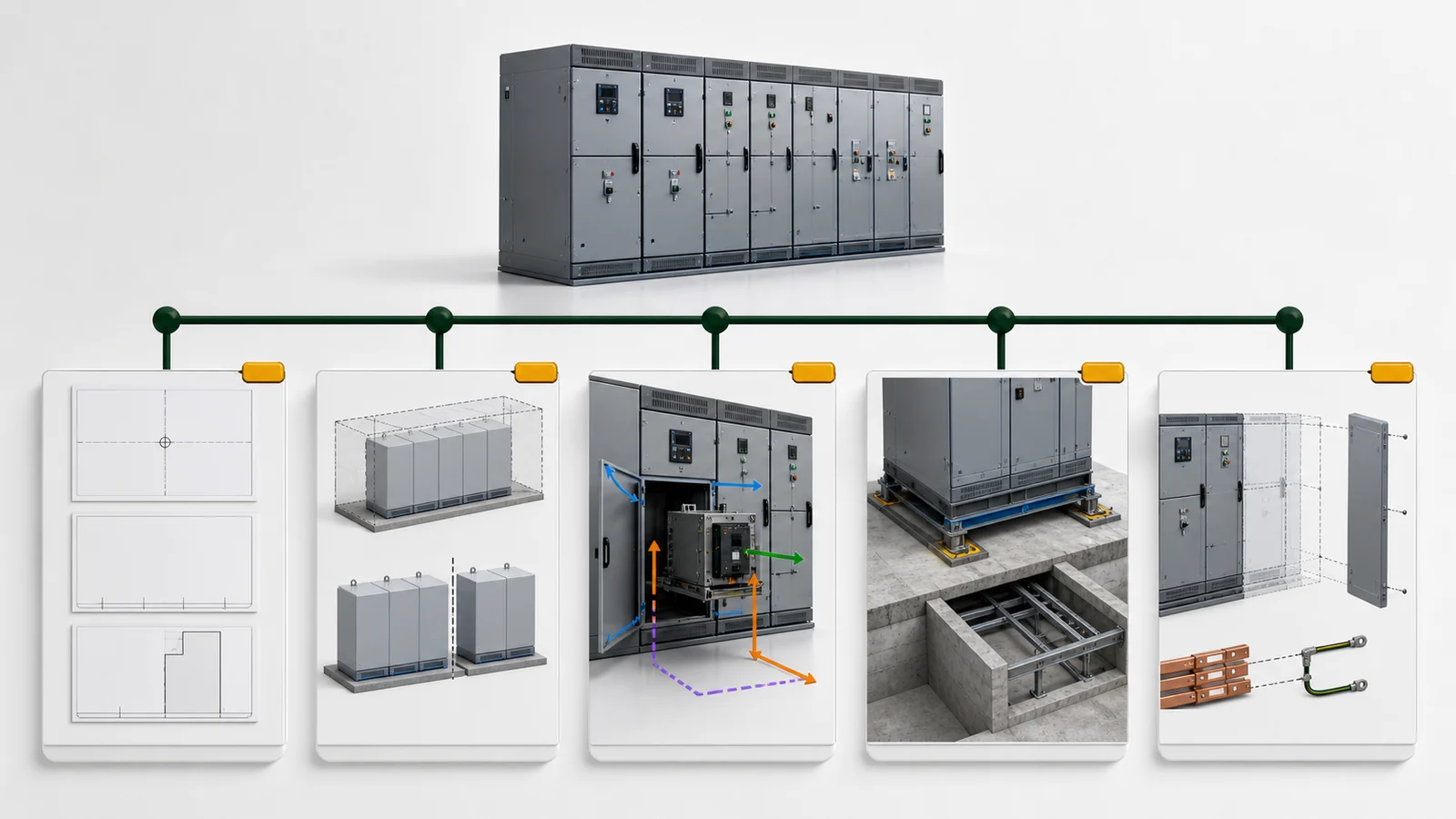
Start with one source set: the current SLD and bay schedule, the supplier GA at its stated revision, and the civil room plan. The complete switchgear cabinet range establishes the cabinet-family context, while the medium-voltage switchgear RFQ data guide owns the earlier functional lineup, fault-duty, protection, and preliminary room inputs. This GA review begins when that lineup must occupy a defined building zone.
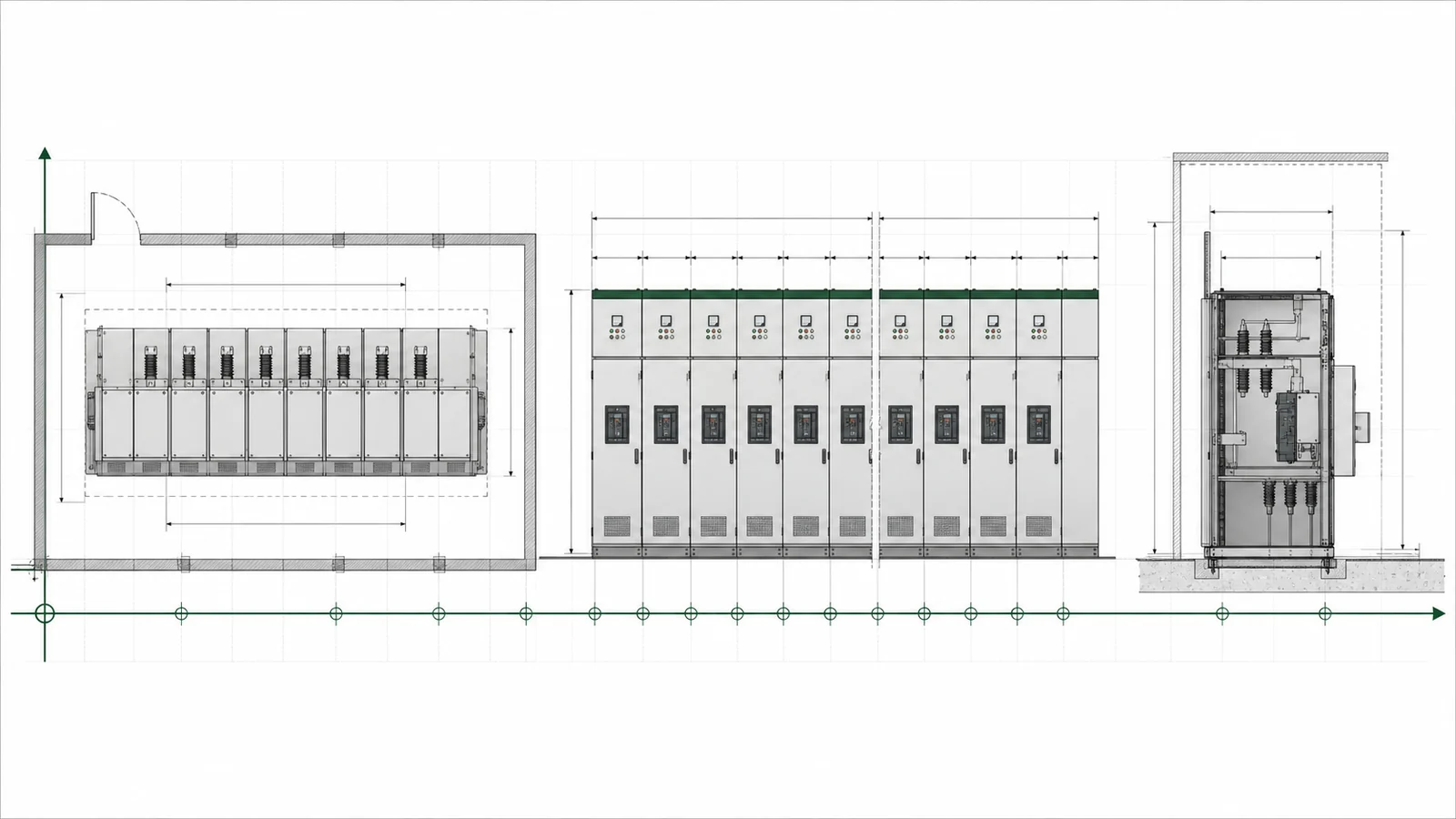
Reconcile the plan, elevation, and sections together. Record individual bay widths, total length, depth, height, end-panel treatment, handles and housings outside the nominal envelope, top or rear projections, and every shipping split. The bay count and sequence must match the bay schedule. The room grid, equipment datum, and finished-floor datum need visible origins rather than assumed alignment.
An apparent plan-view fit can still fail coordination. An elevation may show conflict with a soffit or overhead service; a section may expose a rear projection; an end panel may be excluded from the listed total; or the largest shipping section may not fit the building route. Mark each relationship on a coordinate comparison and retain the source drawing revision beside it. A dimension copied into an email is not a controlled source.
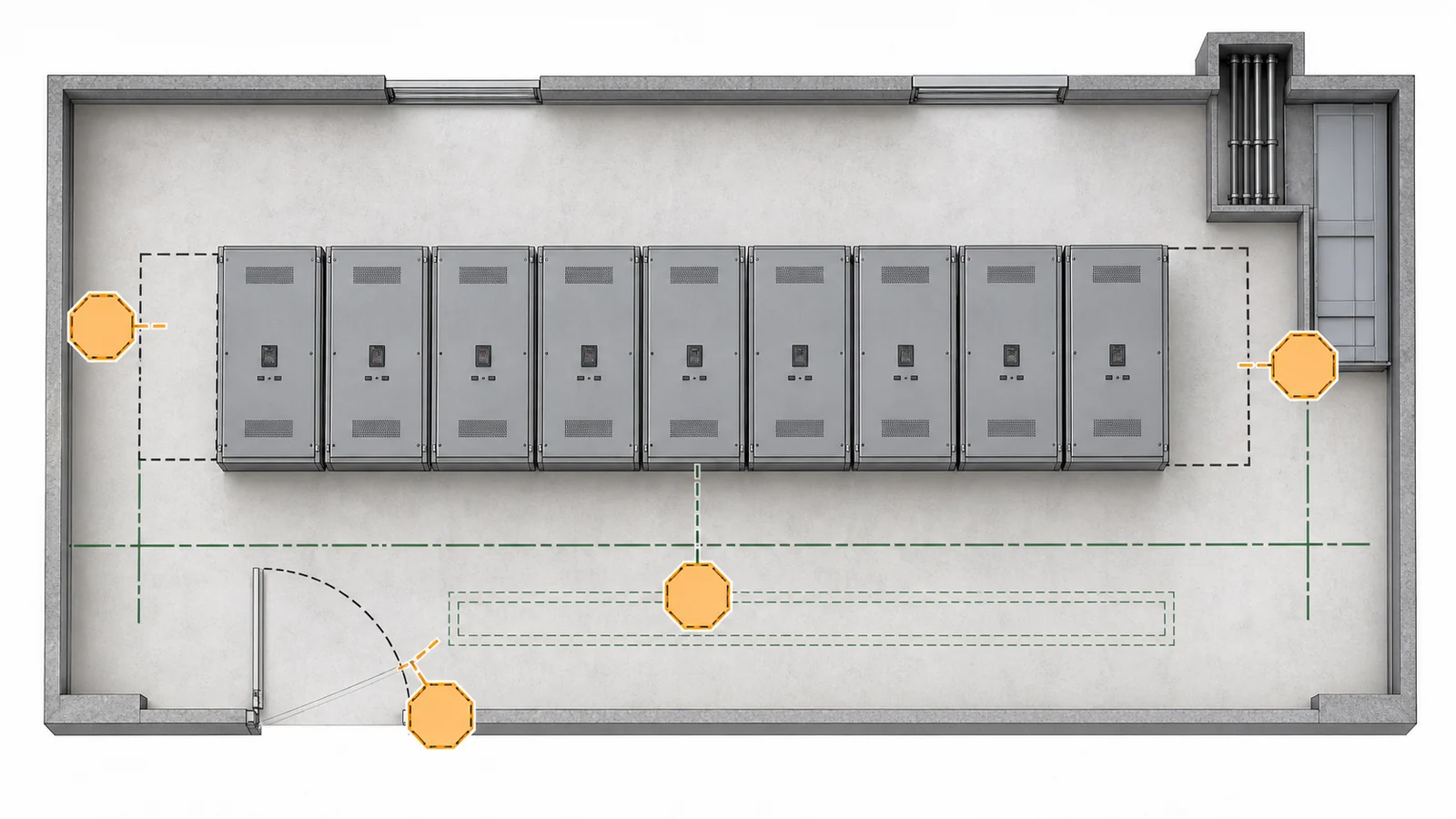
Access is not one nominal aisle number. Review the space occupied while a door or shutter moves, a withdrawable unit reaches its disconnected position, a technician works with tools, a panel section is removed, and lifting or rolling equipment carries that section to the building exit.
For the front, rear, and sides, overlay every relevant door arc, removable cover, truck path, and temporary service zone. Trace the largest transport split through the switchgear-room door, corridor, turns, level changes, and lifting point. Confirm the route against structural openings and permanent services. Construction-phase obstructions such as scaffolding or cable-drum stands also need an owner and sequence if they can block an otherwise usable route.
Keep escape paths visible in all intended operating and maintenance states. Do not infer that a wide-looking plan area is acceptable: the project specification and responsible engineer define the required access basis. The GA review only determines whether the returned geometry supports that basis or remains on hold. It does not claim that site access has been measured or demonstrated.
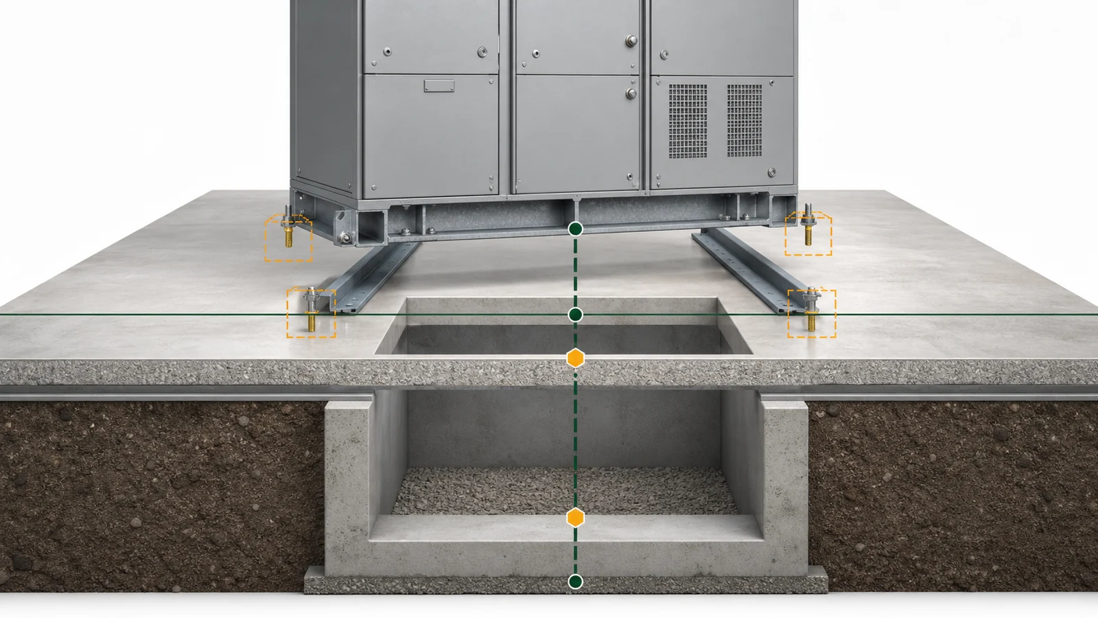
The supplier base and civil structure must share one reference system. Compare the base channel, rail or plinth arrangement, anchor zones, footprint, equipment weight source, finished-floor relation, trench centerline, and floor-opening edges. Structural review should reference the same returned footprint and weight state used by the GA; a later equipment change can reopen the civil decision.
Create an interface table with at least these ownership questions: who defines the equipment base and anchor exclusion zones; who designs and installs the rails, plinth, trench, and covers; who confirms floor loading; who owns waterproofing, drainage, fire stopping, and edge protection; and who issues the reconciled coordinate drawing. Missing ownership is a hold even when dimensions appear to align.
This gate ends at the civil volume and entry coordinates. Detailed cable route, bend radius, straight approach, CT passage, screen-earth routing, terminations, gland plates, cleats, and sealing remain with the MV switchgear cable-entry and termination review. The GA supplies controlled opening and datum inputs to that later review; it does not prove cable fit.
Treat future extension as a physical interface. State the extension direction and intended bay width, then verify the reserved floor zone against walls, columns, ducts, doors, and structural elements. Confirm whether the end panel is removable and whether the supplier has defined a concept for main-bus and earth-bar continuation plus a temporary protected end condition. These are existence and coordination checks, not final extension design.
The civil package should also preserve the related floor, trench, and handling volume. A note saying “future extension possible” does not close the gate if the adjacent space is already occupied or the end condition is undefined.
Use this GA review and RFQ checklist before technical release:
The resulting data pack is the technical basis for a separate authorized civil or manufacturing release; the GA does not release either scope by itself. Drawing identity, revision, transmittal, comment closure, and release status remain governed by the switchgear drawing revision control process.
The following is an entirely synthetic representative engineering review created only to demonstrate the method. It is not a XIYA POWER customer project, quotation, order, drawing, factory record, inspection, installation, commissioning, or field case. Every value is invented, is not a standard minimum or recommended tolerance, and requires project-specific confirmation.
The synthetic inputs describe an indoor 12 kV-class, nine-panel metal-enclosed lineup. The supplier return states 8,400 mm overall length, 1,500 mm depth, and 2,400 mm height. The civil return shows an 8,250 mm equipment zone, 1,800 mm nominal front zone, 1,200 mm nominal rear zone, and 2,200 mm equipment-door opening. A civil trench is returned as 800 mm clear width by 900 mm depth, with its centerline shown 120 mm from the equipment-entry datum used on the supplier return. The request also includes one future 800 mm bay at the right-hand end.
| Open hold | Synthetic mismatch | Evidence needed before any decision |
|---|---|---|
| Envelope | The 8,400 mm returned lineup does not fit the 8,250 mm equipment zone; end-panel inclusion and dimension ownership are not reconciled. | A jointly reconciled envelope basis and controlled supplier/civil returns |
| Access and handling | A door swing reduces the nominal front zone, while the 2,200 mm opening has no transport-split or panel-removal-path evidence. | Door-sweep overlay, transport-split data, route check, and responsible approval |
| Foundation and trench datum | The equipment base/anchor return and civil rail or plinth detail lack one stated datum; the 120 mm relationship is not confirmed on both records. | One reconciled datum record and matched supplier/civil coordinates; cable fit remains out of scope |
| Extension | The requested 800 mm right-end reserve conflicts with a synthetic wall/duct zone; removable end, bus/earth continuation, and temporary closure details are absent. | A coordinated reserved zone and returned supplier end/continuation evidence |
Neither the GA nor a corrected layout is selected, approved, or release-ready. All four holds remain open. Missing evidence does not prove that the design passes or fails, was manufactured incorrectly, or was installed incorrectly.
For a project-specific controlled GA package, use the XIYA POWER contact page to send the bay schedule, room/civil drawings, and supplier return together.
It should include dimensioned plan, elevation, and section views; the matched bay sequence; individual and overall dimensions; end panels and projections; transport splits; equipment and finished-floor datums; base and anchor interfaces; floor openings and trench coordinates; access and handling zones; and future-extension conditions. Each sheet also needs a controlled identity, revision, and status.
Check the complete lineup length, depth, height, individual bay widths, end-panel basis, and every projection against the clear equipment zone. Check shipping-section dimensions against the full handling route and relate the equipment datum and floor level to the civil grid. Use project-controlled sources rather than universal values.
Review access as swept volumes. Overlay door and shutter arcs, withdrawable-unit movement, work positions, panel replacement, lifting or rolling equipment, and the route to the building exit. Confirm that escape paths remain available in intended operating and maintenance states and record the project acceptance source.
The project specification should assign it. A typical responsibility split, subject to the project contract, is for the supplier to return equipment base and entry information, civil disciplines to define the constructed support and trench, and the EPC or responsible engineer to reconcile the interface. The actual contract controls. One shared datum and a signed-off coordinate record are more important than an assumed generic split.
Reserve the intended bay and handling volume in the confirmed extension direction, free of permanent conflicts. Obtain evidence for a removable end condition, main-bus and earth-bar continuation concept, temporary protection, and corresponding floor or trench provision. A future-extension note without physical space is not sufficient.
No. Approval of one GA revision does not by itself prove that dependent civil, access, trench, or extension interfaces are closed. Each gate needs its required evidence and authorized release state. Where a hold remains open, the affected scope should stay outside release until the designated owner closes it through the controlled project process.