Quotation form
Send an inquiry
Start with the basics. Our team can follow up for missing drawings, standards or packing details.
Submitted details are used only for quotation, technical review and project communication.

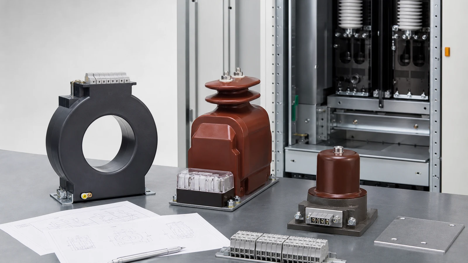
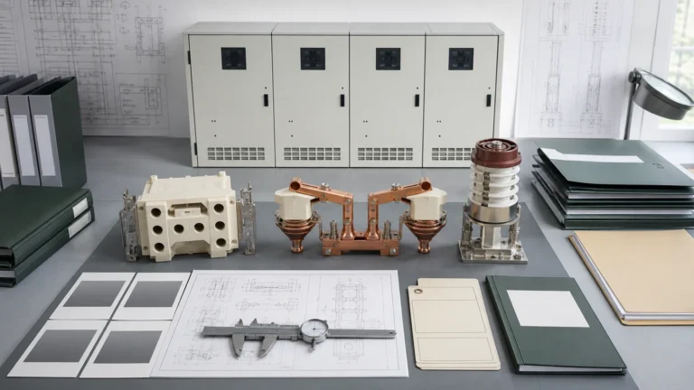
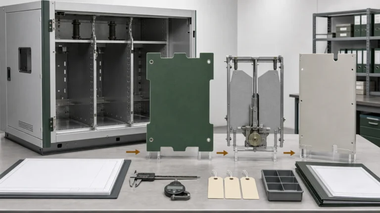
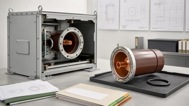
All images are generated illustrative technical visualizations, not XIYA POWER factory, product, metering, protection-operation, installation, calibration, test, commissioning, maintenance, or field photographs.
A switchgear sensor instrument transformer accessories review starts with the circuit function, not the outline shape. Ratio, class, burden, wiring, duty, and cabinet fit must close against one approved design revision. A photo can support identity, but it cannot release an electrical or mechanical interface.
Identify the bay, circuit, and sensing purpose before comparing products. State whether each core or channel supports measurement, protection, control, or monitoring. This prevents a visually similar accessory from inheriting an unverified duty.
The sensor and instrument transformer accessories range provides the product-owner route for CTs, VTs, sensors, and related parts. Its drawings can support dimensions, mounting, terminal direction, and body form. They do not establish an unstated ratio or application rating.
The wider Switchgear Components pillar places these devices within metering, feedback, monitoring, and protection interfaces. Use both pages for routing and product context, then return to controlled project evidence for release.
Use a selection matrix so every decision has a required input and release evidence.
| Decision | Required input | Evidence source | Offered return | Release evidence | Hold condition |
|---|---|---|---|---|---|
| Circuit and function | SLD, bay ID, purpose per core or channel | Approved SLD and schedule | Identified accessory position | Position and purpose map to one circuit | Circuit ownership is unclear |
| Ratio or output | Primary quantity, secondary quantity, taps, signal type | Metering or protection schedule | Nameplate and datasheet values | Values match the schedule | Ratio, tap, or output is open |
| Class and burden | Class per core, connected load, lead data | Project specification and calculation | Class and rated burden | Controlled calculation fits the rating | Inputs or class are unresolved |
| Fault or voltage duty | System and study inputs | Short-circuit study and specification | Declared withstand or voltage factor | Offered duty covers the requirement | Duration or rating differs |
| Wiring | Polarity, terminal map, connector, grounding and shield route | Wiring and terminal drawings | Terminal diagram and pinout | Every terminal maps across revisions | Cross-reference is absent |
| Physical fit | Aperture, body, base, holes, orientation, access | Cabinet overlay and dimensioned drawing | Controlled outline drawing | Tolerances and access close | Any interface remains assumed |
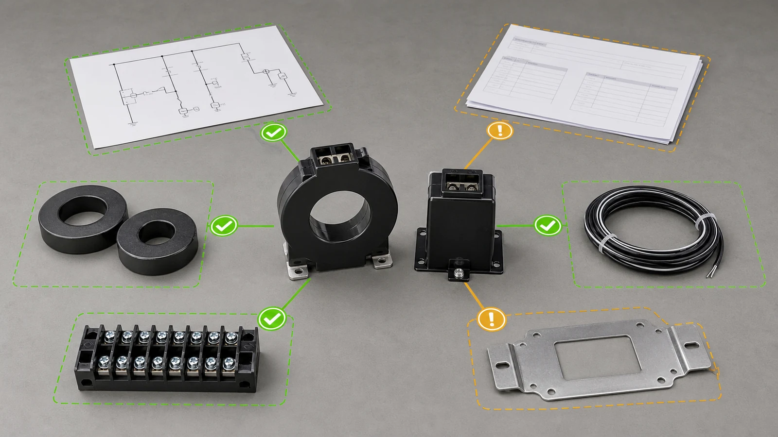
Treat the matrix as a decision record. A missing source, owner, or revision is itself a hold condition, even when the offered item looks familiar.
Ratio defines the relationship between primary and secondary quantities. Available taps also need an explicit schedule match. A nearby ratio or an undocumented tap position cannot substitute for the specified value.
Assign every core or channel to one approved purpose. Metering and protection cores can carry different classes and burdens, so they cannot be exchanged silently. The nameplate confirms offered data; the circuit schedule confirms whether that data is suitable.
For a conventional instrument transformer, compare rated burden with the calculated connected burden. Include each meter or relay input, secondary lead resistance, terminal losses, and test-link losses. Lead length, conductor cross-section, and calculation revision must be controlled.
A low-power or digital sensor may use a rated analogue output or a digital interface instead of a conventional VA burden model. Verify signal type, level, connector, protocol, and receiving input together. Never convert that interface into a conventional burden check without applicable manufacturer data.
Keep frequency and duty separate from ratio and class. CT short-time and dynamic withstand must be compared with the project fault input. VT voltage factor and duration must follow the approved system and earthing requirements.
The complete MV switchgear RFQ data guide owns the upstream SLD, protection schedule, metering responsibility, and fault-current inputs. COMP-08 consumes those approved inputs; it does not create relay settings or a complete metering schedule.
The official IEC 61869-1:2023 publication page defines general requirements for newly manufactured instrument transformers above 1 kV AC or 1.5 kV DC. It covers analogue or digital secondary signals used for measurement, protection, and control. The relevant product-specific standard is also required. This public scope does not provide project ratios, classes, burdens, or fault duties.
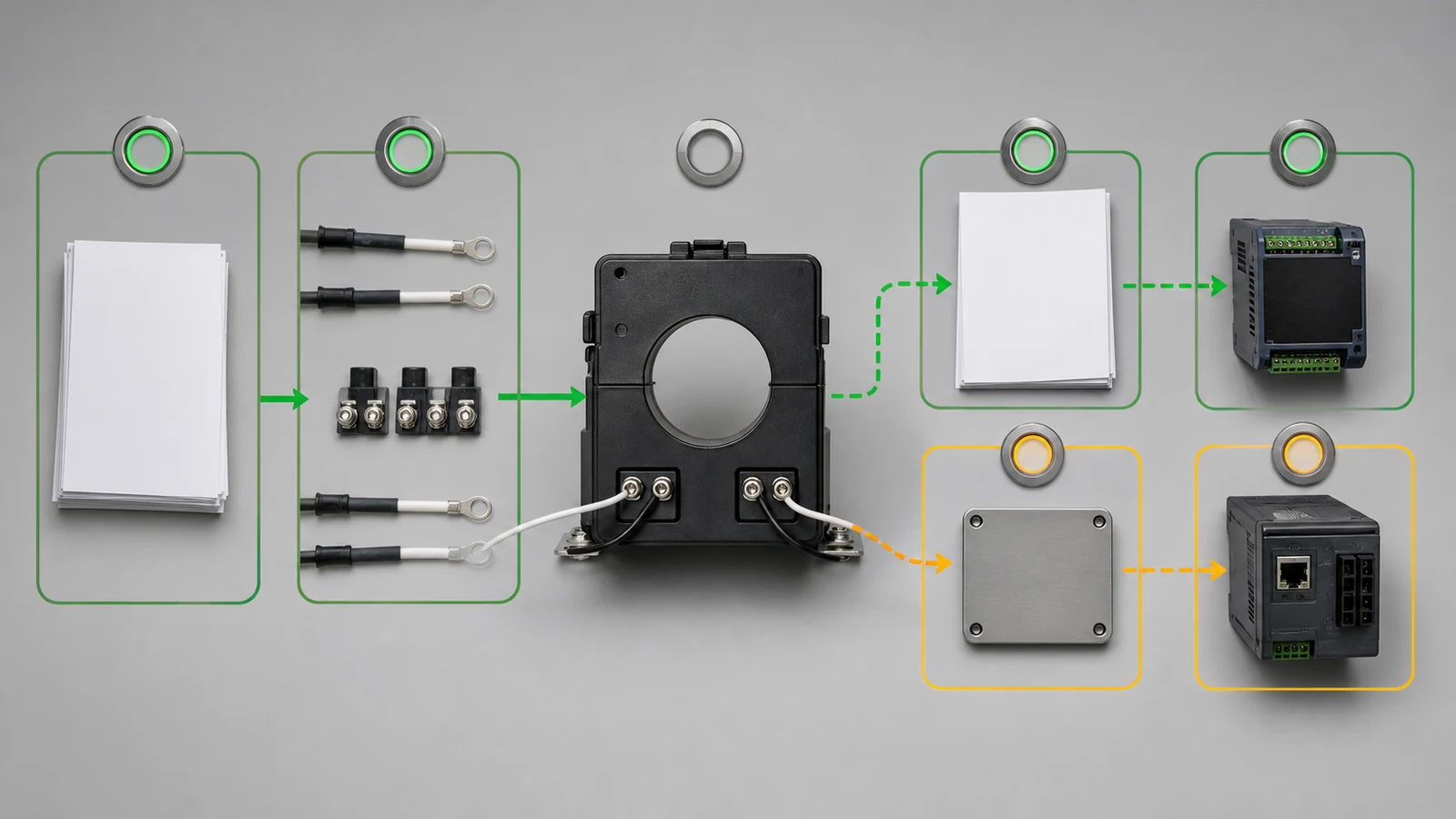
A technical release therefore needs both sides of the comparison. Project evidence states the required duty, while current manufacturer data states the offered capability.
Terminal designations vary across manufacturers and drawing conventions. Primary and secondary labels must be cross-referenced explicitly. Similar-looking notation cannot prove equivalent polarity or circuit direction.
Map each device terminal to its cabinet terminal block, destination, function, and drawing revision. Multi-core devices also need unique core identifiers that agree across the nameplate, terminal drawing, and circuit schedule.
Treat grounding and shielding as project-defined interfaces. The approved wiring design must identify the grounding point and shield route. This article does not prescribe a universal point, terminal, or energized work procedure.
Active and digital sensors may add auxiliary supply, polarity, connector, pinout, address, or communication requirements. Verify those items against the exact receiving device. A compatible physical connector does not prove electrical or protocol compatibility.
CT secondary circuits also need a defined shorting and test boundary on the approved drawing. Equipment-specific and site-specific instructions govern handling. COMP-08 records required interfaces but does not provide calibration, installation, or testing procedures.
Use a cross-reference table during technical review:
| Wiring item | Project return | Manufacturer return | Release evidence | Hold condition |
|---|---|---|---|---|
| Primary polarity | Drawing labels and direction | Device labels and polarity mark | Approved notation map | Mapping is assumed |
| Secondary terminal | Core, terminal block, destination | Core and terminal labels | End-to-end schedule | Destination or core is unclear |
| Ground and shield | Approved circuit route | Permitted terminal interface | One coordinated drawing | Route or owner is absent |
| Active interface | Supply and receiving input | Pinout, output, protocol | Matched interface schedule | Level, pin, or protocol differs |
| Test boundary | Shorting and test-link drawing | Device terminal requirements | Equipment-specific scheme | Boundary is undocumented |
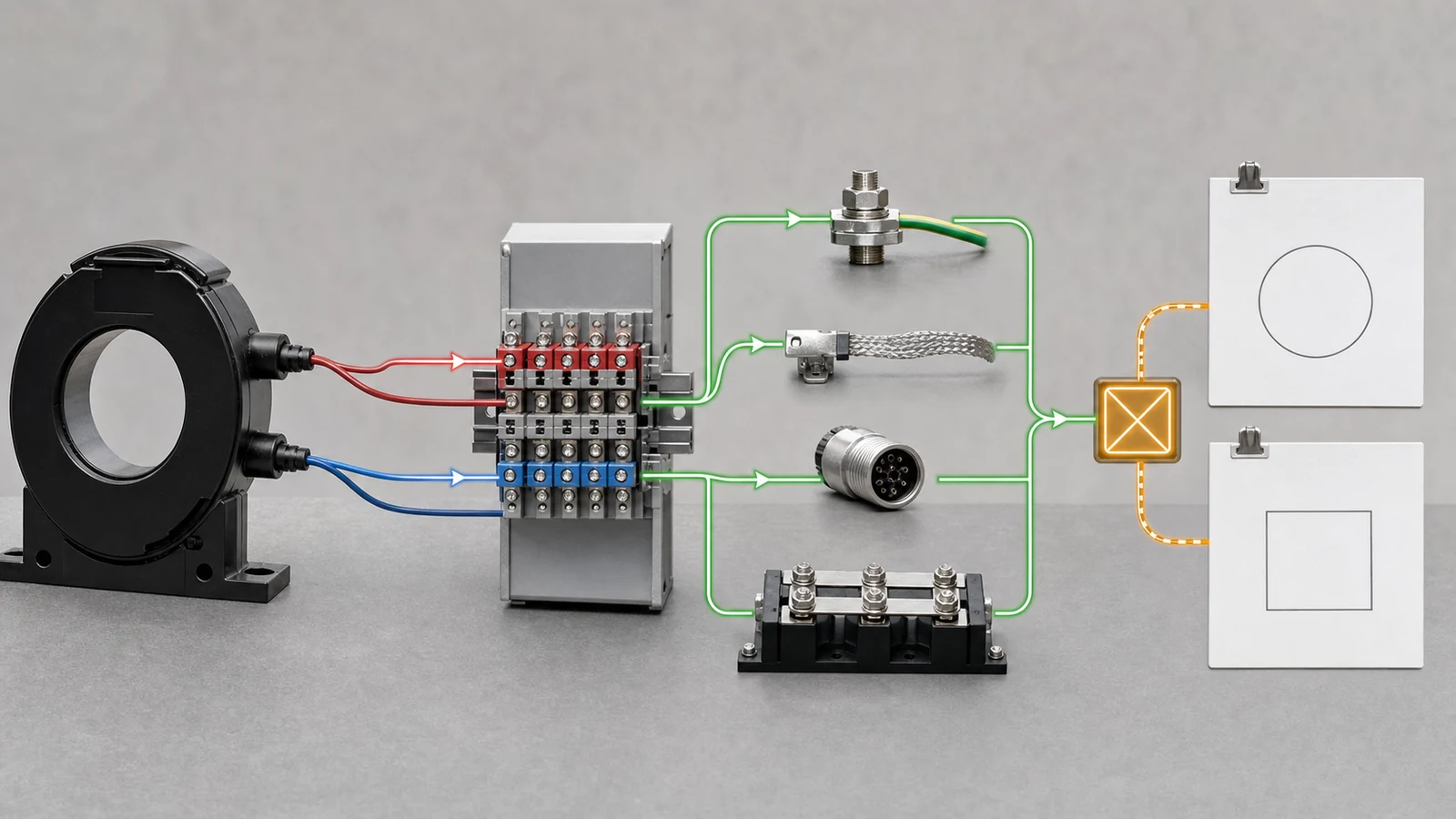
This table documents compatibility. It does not claim that an accessory has been wired, energized, calibrated, or tested.
Electrical suitability cannot release a part that does not fit the cabinet. Compare the device drawing with the same cabinet revision used for the circuit review.
For a ring device, check the complete primary conductor or cable envelope. Include insulation, supports, tolerances, and assembly clearance. Nominal aperture alone is insufficient when the remaining margin is unknown.
Compare the mounting base, hole pattern, fixing hardware, device weight, and support arrangement. A small hole-pattern difference creates a design change rather than an automatic fit. Any adapter or drilling change needs a controlled disposition.
Orientation controls polarity, terminal access, cable exit, and removal space. Show adjacent conductors, terminals, shutters, baffles, partitions, and moving parts on the overlay. COMP-08 checks accessory fit but does not own their movement or segregation acceptance.
The KYN28 switchgear specification provides cabinet-family context for CT and VT positions, compartment arrangement, and accessory locations. A cabinet-family page cannot replace the project general arrangement or the offered accessory drawing.
Record dimensions and tolerances in one overlay. Keep an interface on hold when body clearance, terminal reach, cable bend, fastener access, or removal path remains unresolved.
Turn the RFQ checklist into a revision-controlled data pack. Separate identity evidence, electrical evidence, wiring evidence, and dimensional evidence so one document cannot answer a different question.
| Data pack item | Required input or return | Technical release condition |
|---|---|---|
| Circuit package | SLD, bay ID, function, core or channel schedule | One approved circuit revision |
| Ratings package | Ratio, taps, class, burden or output, frequency, duty | Requirements map to offered data |
| Calculation package | Connected load, leads, terminals, fault inputs | Inputs, method, and revision are controlled |
| Wiring package | Polarity, terminal map, connector, supply, ground, shield | End-to-end cross-reference closes |
| Product package | Nameplate, current datasheet, applicable evidence | Exact offered model is identified |
| Fit package | Outline, aperture, holes, tolerances, orientation, access | Cabinet overlay closes every interface |
| Control package | Revision register, deviations, owners, dispositions | No silent assumption remains |
The switchgear component acceptance checklist owns incoming inspection after procurement. COMP-08 owns the earlier selection and approval data. Receiving inspection cannot repair an incomplete technical release.
Require a clear applicability statement for each manufacturer document. Generic brochures and unrelated evidence should not be used to close the exact model. Record open deviations with an owner and required return.
Representative engineering review, not a XIYA POWER customer, supplier, factory, product, metering, protection-operation, installation, calibration, test, commissioning, maintenance, failure, or field case. The system values, ratings, terminal notations, dimensions, findings, and decisions are illustrative and non-universal.
The synthetic review concerns one 12 kV, 50 Hz feeder CT accessory. The request states 600/1 A with two cores. One metering core needs class 0.5 at 10 VA. One protection core needs 5P20 at 15 VA.
The synthetic connected-burden return states 7.6 VA for metering and 13.4 VA for protection. Lead length, conductor size, terminal losses, and calculation revision are uncontrolled.
The project fault input states 25 kA for 3 seconds. The offer states 25 kA for 1 second. The project uses P1/P2 and S1/S2, while the offer uses K/L and k/l without a cross-reference.
The primary conductor and support envelope is 78 mm. The offered aperture is 80 mm, but tolerance and assembly clearance are missing. The existing mount is 140 mm by 140 mm, while the offer shows 145 mm by 145 mm. Its secondary cable exits opposite the cabinet overlay.
Synthetic illustrative review table:
| Decision | Observed return | Release state | Required evidence | Hold condition |
|---|---|---|---|---|
| Ratio, cores, and class | Requested values appear in the return | Hold | Core-purpose map, terminal map, and applicable evidence | Schedule mapping is incomplete |
| Connected burden | 7.6 VA and 13.4 VA estimates | Hold | Controlled leads, conductor, terminal losses, and revision | Calculation inputs are uncontrolled |
| Fault duty and polarity | 25 kA durations differ; notation is unmapped | Hold | Duty comparison and approved cross-reference | Duration and polarity remain open |
| Physical fit and exit | Aperture margin, hole pattern, and cable exit conflict | Hold | Toleranced overlay and approved disposition | Fit is not demonstrated |
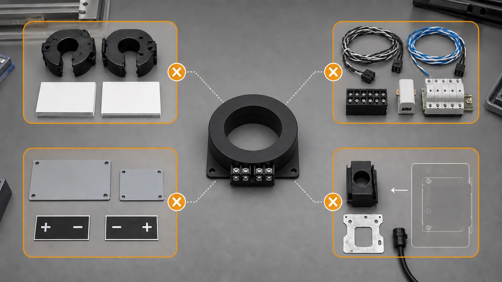
No statement is made that the offered CT is accepted, rejected, accurate, saturated, installed, calibrated, tested, commissioned, or operating. Each hold requires separate evidence before closure.
Provide the SLD, bay ID, purpose per core or channel, project specification, ratings schedule, fault input, burden or interface calculation, wiring package, manufacturer data, and dimensioned cabinet overlay.
No. Core assignment, class, burden, fault duty, polarity, terminal mapping, aperture, mounting, orientation, and cable exit are independent decisions. Every applicable interface must close.
Add device loads, lead resistance, terminal losses, and test-link losses using controlled inputs. Compare that total with the rated burden and required class for the same core.
No. Compare the project wiring drawing with the manufacturer terminal diagram. Document polarity and terminal equivalence explicitly before technical release or wiring.
Check aperture, conductor and support envelope, tolerances, mounting base, hole pattern, outline, orientation, terminal access, cable exit, adjacent clearances, and removal space on matched revisions.
Keep it on hold whenever a rating, calculation input, document revision, terminal map, duty, tolerance, clearance, or owner remains unresolved. Visual similarity never closes missing evidence.