Quotation form
Send an inquiry
Start with the basics. Our team can follow up for missing drawings, standards or packing details.
Submitted details are used only for quotation, technical review and project communication.

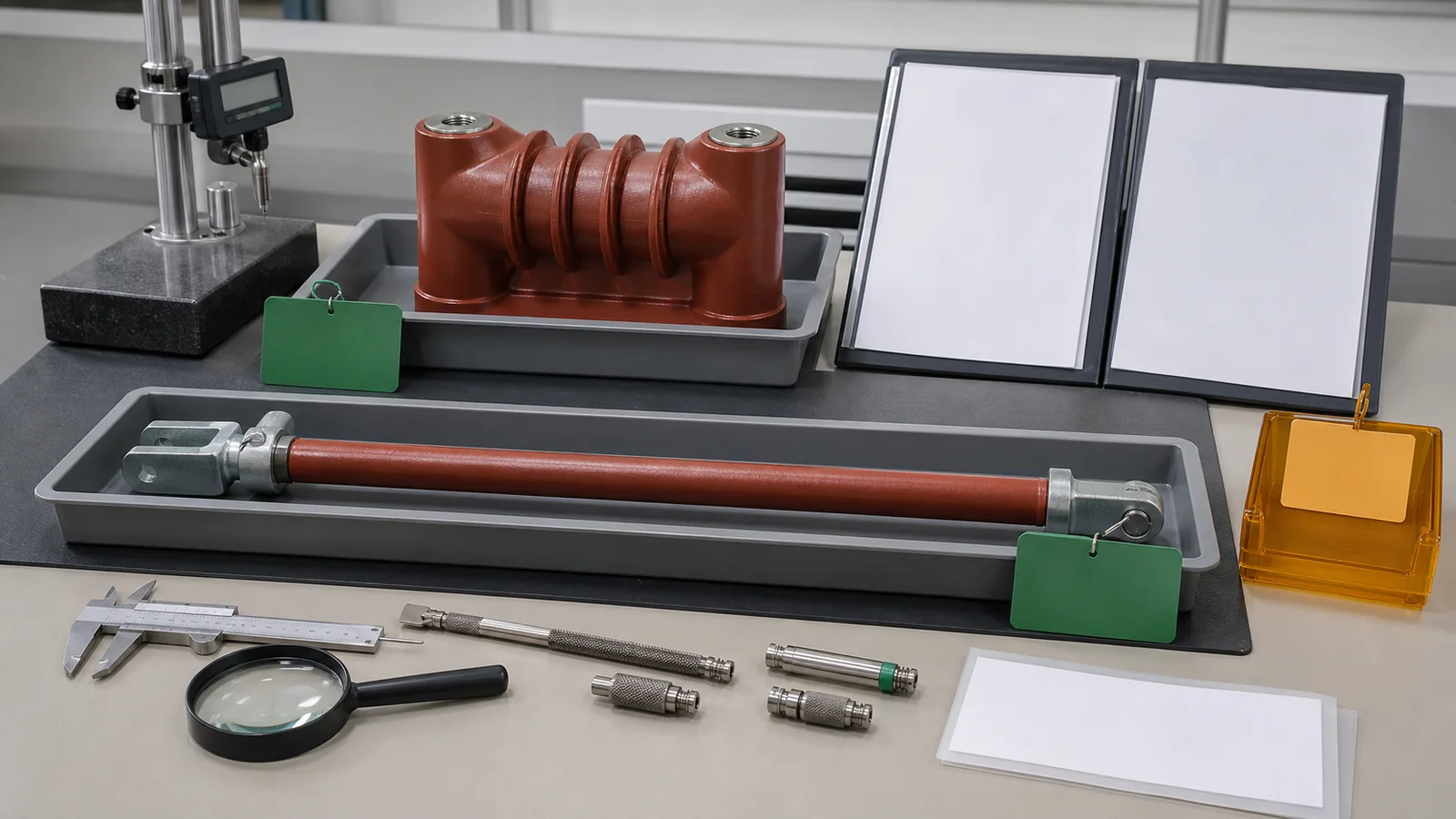
Switchgear resin insulator acceptance is a controlled release decision, not a visual sort. Release a received lot only when identity, drawing revision, surface condition, critical dimensions, mechanical duty, applicable evidence, and traceability agree. A dimensional pass cannot override a crack-like indication, an unmatched certificate, or evidence that does not cover the received configuration.
Visual disclosure: all images are generated illustrative technical visualizations, not XIYA POWER factory, design, inspection, test, FAT, manufacturing, installation, commissioning, or field photographs.
Freeze the inspection basis before unpacking or cleaning parts. Identify the lot boundary, part number, quantity, supplier marking, approved drawing revision, project specification, inspection plan, sample plan, and release authority. Otherwise, a technically neat inspection record may still describe the wrong part population or revision.
The resin insulator and pull rod product owner is the model-photo and drawing starting point. The Switchgear Components pillar locates these parts within primary-insulation and mechanism zones. Use the component acceptance checklist for the family-level lot and document gate. COMP-07 adds the part-specific release layer.
| Acceptance matrix gate | Acceptance source | Required record | Release state | Hold condition |
|---|---|---|---|---|
| Identity and lot boundary | Purchase order, approved drawing, marking | Part number, revision, lot, quantity, package map | Inspect | Marking, revision, or quantity conflict |
| Controlled documents | Drawing register, project specification, inspection plan | Applicable-document list | Inspect | Missing or superseded source |
| Sample definition | Approved sampling plan | Population, sample IDs, selection basis | Inspect | Undefined population or sample |
| Surface and interfaces | Drawing, workmanship standard, approved sample | Sample-level visual record | Accept or hold | Finding lacks an applicable criterion |
| Dimensions | Released drawing and method | Datum, instrument status, result, tolerance source | Accept or hold | Out-of-tolerance or invalid method |
| Duty and qualification | Design source and inspection plan | Applicable report or declaration | Accept or hold | Configuration or load path not mapped |
| Traceability and release | Lot records and named authority | Signed release, hold, deviation, or rejection | Close | Any gate remains open |
`
`
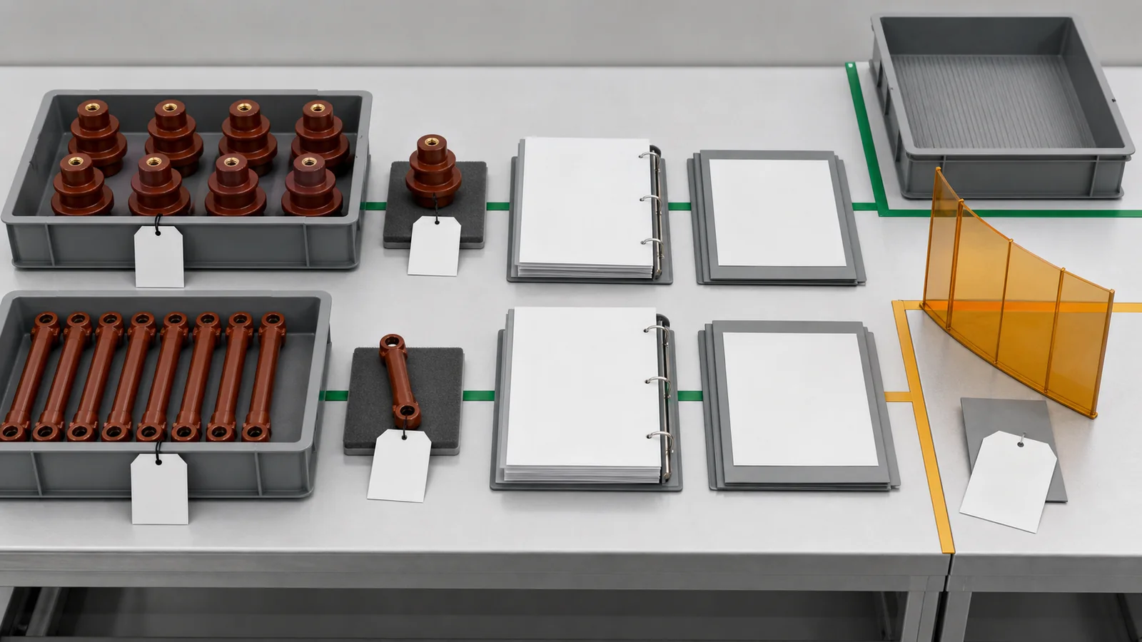
One delivery may need several lots when markings, molding batches, drawing revisions, end fittings, or certificates differ. Several cartons do not become one lot merely because their labels show the same family name. Preserve the as-received package and marking evidence before inspection changes the condition.
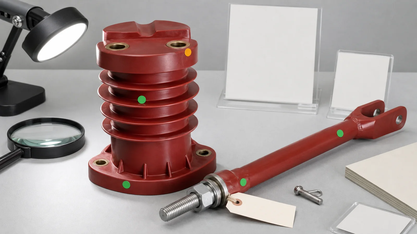
A support insulator carries an insulation role and a defined mechanical load path through its molded body and inserts. An insulating pull rod transfers motion or force while preserving an insulation boundary. Their critical inspection zones are therefore related but not interchangeable.
Inspect every selected sample under the approved lighting and access conditions. Give special attention to loaded transitions, insert and fitting interfaces, mounting faces, insulation paths, ribs or sheds, threads, pins, forks, and markings. Record the location and extent of each finding before any permitted cleaning or disposition activity.
| Inspection zone | Look for | Acceptance source | Hold condition |
|---|---|---|---|
| Molded transition around an insert | Crack-like indication, resin disturbance, displaced insert | Drawing and workmanship standard | Loaded transition cannot be dispositioned |
| Ribs, sheds, and insulation path | Chip, exposed material, blister, surface void, repair evidence | Controlled surface criteria | Finding exceeds or lacks a criterion |
| Mounting face and base | Flash, burr, contamination, rocking, deformation | Drawing and approved sample | Seating or datum face is affected |
| Embedded thread or terminal | Corrosion, damage, blocked depth, wrong orientation | Drawing and gauge method | Mating interface is not verified |
| Pull-rod body | Bending, twisting, surface damage, prior repair | Drawing and inspection plan | Insulation or load path is uncertain |
| End fitting, pin, or fork | Damaged thread, bent pin, deformed fork, loose interface | Drawing and workmanship standard | Attachment or load-line alignment is affected |
| Identification | Illegible, mixed, or conflicting mark | Traceability plan | Sample cannot be tied to its lot |
Surface appearance alone does not create a universal decision. A color variation, molding line, small mark, bubble, or inclusion is not automatically acceptable or rejectable. Use the applicable controlled document, approved sample, project specification, or authorized deviation. The switchgear component foundation owns the basic role and cabinet-zone explanation.
`
`
Do not polish away a finding to make the part look acceptable. Any permitted cleaning, repair assessment, or reinspection must preserve the original record and follow an approved route.
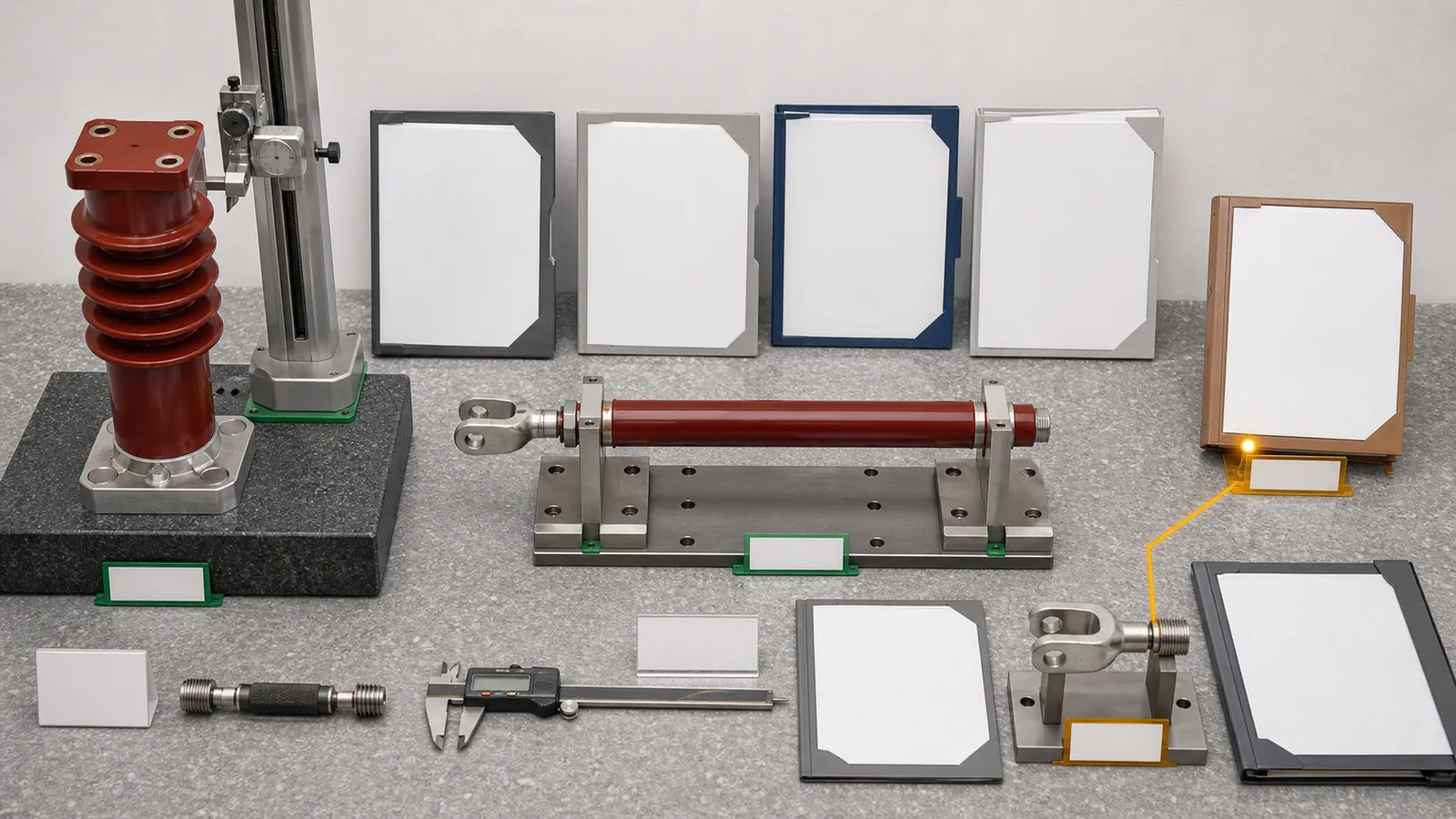
Measure from the released drawing datums, not from appearance or a convenient edge. A removed old part may support identification, but wear, deformation, coatings, repair history, and unknown inspection state prevent it from becoming the acceptance master.
| Part | Drawing-controlled feature | Suitable evidence | Common invalid shortcut |
|---|---|---|---|
| Support insulator | Mounting-face to top terminal or insert datum | Height method or fixture tied to released datum | Overall height from an undefined edge |
| Support insulator | Insert pattern, offset, depth, thread, and orientation | Coordinate, depth, and specified thread-gauge records | Hole spacing only |
| Support insulator | Base, top face, and envelope | Flatness or envelope method where specified | Visual seating judgment |
| Pull rod | Pin-center or end-to-end length | Released fixture or controlled dimensional method | Comparison with a used rod |
| Pull rod | Fork width, pin hole, thread, and end orientation | Specified gauges and angular/datum method | Thread engagement by hand |
| Pull rod | Straightness and load-line alignment | Approved support and measurement method | Rolling the part on a bench |
Each result needs the part and sample ID, drawing revision, datum, method, instrument identity, calibration or verification status, result, tolerance source, inspector, and date. Record ambient conditions only when the method or specification makes them relevant. An instrument status field should never be replaced by the word calibrated without an identifiable record.
Use the specified tool for the characteristic. Calipers cannot replace a thread plug gauge, depth method, fixture, height system, or optical method when the inspection plan calls for one. Receiving acceptance is also separate from cabinet-interface selection. The wall-bushing and contact-box selection guide owns that sibling fit stack.
`
`
If a measurement is near a limit, follow the defined decision rule for resolution, repeatability, and uncertainty. Do not average away a failing sample or silently substitute a different datum.
A correct outline does not prove mechanical duty. The acceptance file must identify the specified load mode, direction, attachment geometry, operating duty, and configuration. Tension, compression, bending, torsion, impact, and repeated mechanism motion are different evidence questions.
Map qualification or design evidence to the received drawing revision, resin or core system where controlled, embedded insert, end fitting, geometry, process, and load direction. A family report is not automatically applicable after one of those characteristics changes. The mapping should name exclusions and the authority that accepts any extension or deviation.
The official IEC 62217:2025 scope includes polymeric insulators whose insulating bodies use organic material, including resin insulators. Its public page describes common definitions, test methods, and acceptance or failure criteria where applicable. It also states that applicable tests come from the relevant product standard. That scope does not make every switchgear pull rod compliant, provide a part drawing, or release an incoming lot.
Do not proof-load or dielectric-test every received part unless the approved inspection and test plan requires an applicable procedure. Incoming measurement cannot recreate design qualification. Electrical or mechanical tests require qualified personnel, controlled equipment, defined safety boundaries, test records, and project-approved acceptance sources.
Keep these evidence types separate:
The evidence chain must run from each physical item or package to its batch or lot, selected sample, measurement record, certificate, test record, finding, deviation, reinspection, and final authority. If a certificate cannot be tied to the marked lot, its technical content cannot release that lot.
| Controlled state | Meaning | Required record | Next action |
|---|---|---|---|
| Accept | Every applicable gate is closed | Signed release and accepted-lot identity | Move only to controlled accepted stock |
| Quarantine or hold | One or more gates remain open | Hold notice, physical location, affected population | Recover evidence or perform authorized reinspection |
| Conditional release | Named authority accepts a documented deviation | Approved deviation with scope and conditions | Control affected quantity and downstream use |
| Reject | Authorized disposition determines non-use | Nonconformance and rejection record | Segregate and follow the approved return/scrap route |
Sampling records should identify the population and the actual sample-selection basis. A passed sample does not erase a defect found outside the planned sample. A defect may also require containment or expanded inspection when the approved plan says it can affect the wider lot.
Keep original results. Corrections need traceable amendments, not overwritten values. Reinspection records should identify the reason, changed evidence, method, sample scope, and approving authority. Repair, cleaning, retesting, or proof loading cannot proceed only to obtain a pass. Each action needs a controlled basis and preserves the as-received finding.
Storage and handling history may affect the incoming condition record. Detailed humidity control, preservation, cleaning after storage, and post-storage reinspection belong to the Phase 2 storage owner rather than this receiving guide.
Representative engineering review, not a XIYA POWER customer, factory, design, inspection, test, FAT, manufacturing, installation, commissioning, maintenance, or field case. All quantities, dimensions, sample results, lot codes, and findings are illustrative and non-universal.
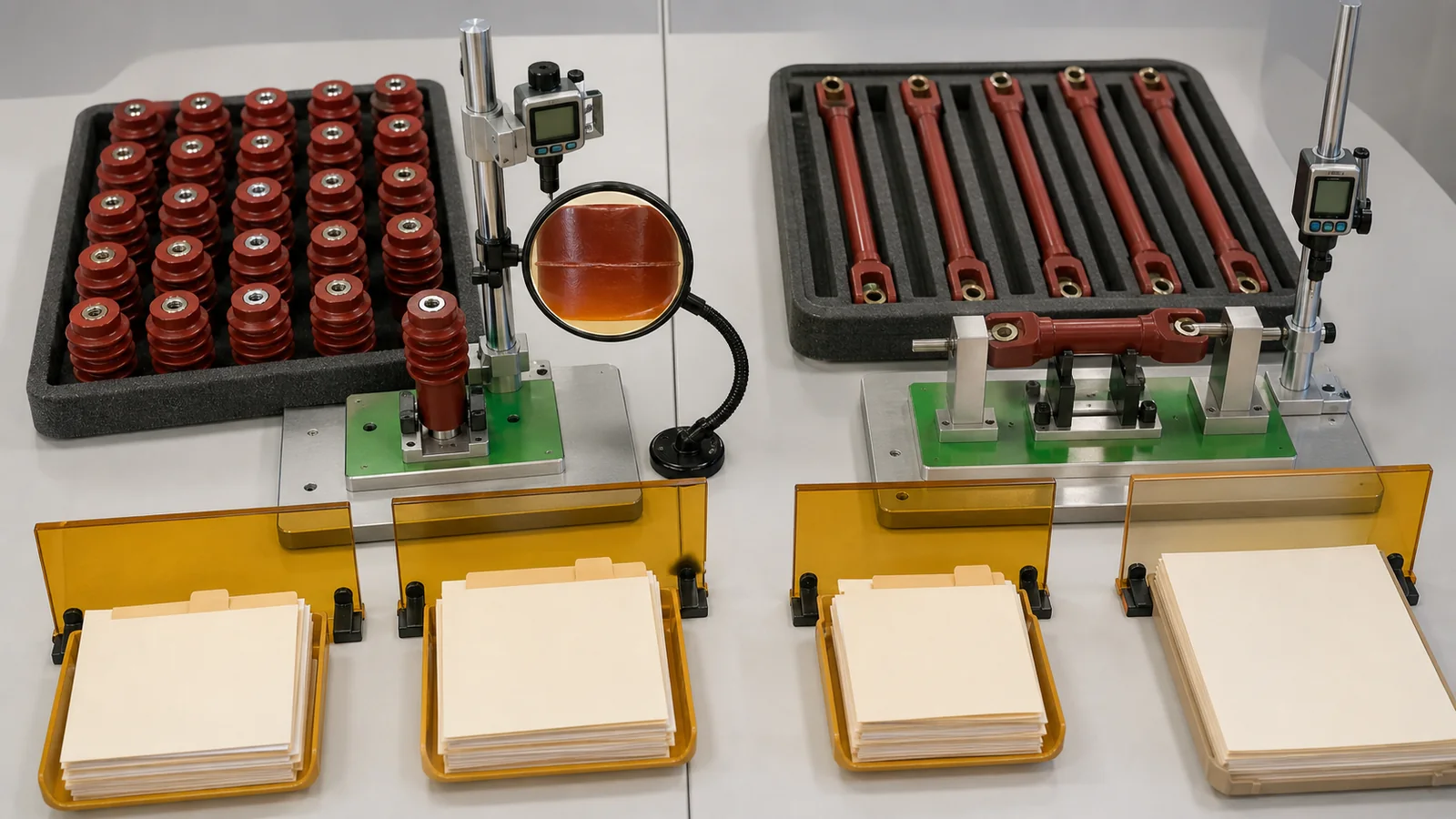
Two illustrative lots contain 24 support insulators and 24 insulating pull rods against controlled drawing revision D. The support-insulator drawing gives a mounting-face-to-top-insert datum of 168.0 +/- 0.5 mm. It also requires an M12 x 1.75 go/no-go thread check. The pull-rod drawing gives a 286.0 +/- 0.6 mm pin-center length.
| Required input | Observed return | Decision | Required record | Hold condition |
|---|---|---|---|---|
| Support-insulator datum | 168.4 mm, inside the illustrative limit | Dimensional gate passes | Sample, method, instrument, datum, and result | None at this gate |
| Support-insulator thread | Specified gauge indicates pass | Thread gate passes | Gauge identity and status | None at this gate |
| Support-insulator surface | Crack-like indication at the insert transition | Hold lot separately | Finding record and controlled disposition | Loaded transition remains unresolved |
| Pull-rod pin-center length | 286.3 mm, inside the illustrative limit | Dimensional gate passes | Sample, method, instrument, datum, and result | None at this gate |
| Pull-rod traceability | Part marking PR-24B; certificate PR-24A | Hold lot separately | Corrected lot-linked evidence | Certificate does not match the lot |
| Mechanical-duty applicability | Family named, but revision, end fitting, and load direction are unmapped | Hold | Configuration-applicability statement | Current design boundary is unproven |
`
`
Passing dimensions do not close the surface, traceability, or mechanical-evidence gates. Require a documented surface disposition and defined reinspection for the support-insulator lot. Require corrected traceability and configuration-applicable mechanical evidence for the pull-rod lot. No final acceptance, rejection, supplier outcome, test pass, design approval, installation, or field result is claimed.
Check lot identity, drawing revision, molded surfaces, inserts or end fittings, critical dimensions, specified mechanical duty, applicable evidence, traceability, findings, reinspection, and authorized disposition.
Not automatically. A crack-like indication, damaged insert, surface finding, wrong revision, missing evidence, or broken traceability can keep the lot on hold despite passing dimensions.
Use the released drawing. It may control pin-center or end-to-end length, insulating envelope, threads, pins, forks, end orientation, straightness, and load-line alignment.
No universal rule applies. Perform only the tests required by the approved inspection plan, applicable product specification, and controlled procedure using qualified personnel and suitable equipment.
Connect physical markings and packages to the lot, drawing revision, samples, inspection results, certificates, test records, deviations, reinspection, and signed release or rejection.
No. It can support identification, but unknown wear, deformation, coating, repair, and measurement history prevent it from replacing the approved drawing and specification.