Quotation form
Send an inquiry
Start with the basics. Our team can follow up for missing drawings, standards or packing details.
Submitted details are used only for quotation, technical review and project communication.

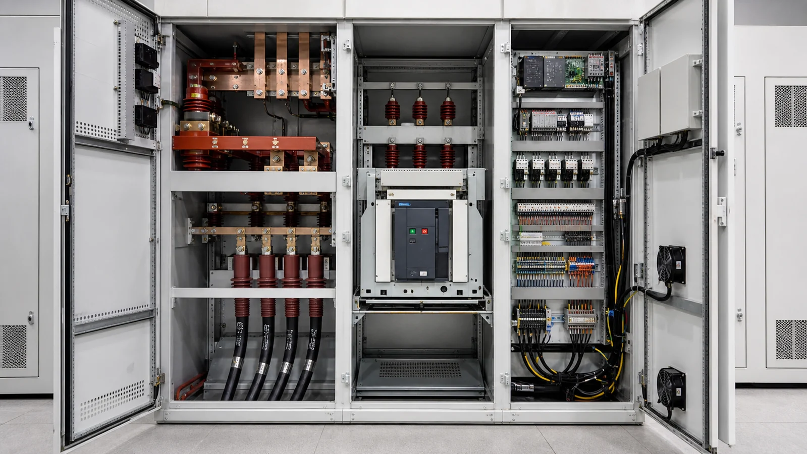
Medium-voltage switchgear cabinets contain six discrete functional zones, each populated by components that serve a specific electrical, mechanical, or insulation role. Understanding which component belongs to which zone—and what interface evidence is required before any part is sourced—is the starting point for safe procurement and maintenance planning.
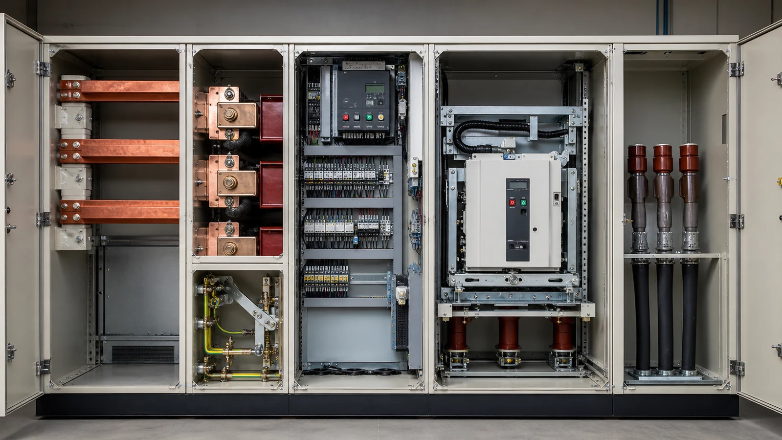
| Cabinet Zone | Primary Function | Representative Components |
|---|---|---|
| Busbar / Insulation Zone | Isolate and carry inter-bay HV busbars | Wall bushing, contact box, insulating barrier |
| Current Path / Contact Zone | Transfer load current through switching interfaces | Contact arm, tulip contact, fixed contact cluster |
| Earthing / Mechanism Zone | Provide safety earthing and mechanical interlocks | Earthing switch mechanism, interlock shaft, position indicator |
| Control / Interlock Zone | Relay secondary signals; prevent mis-operation | Secondary plug, auxiliary contact block, anti-condensation heater |
| Cable Termination Zone | Terminate outgoing MV cables safely | Cable clamp, stress cone, current-limiting fuse, earthing lug |
| VCB / Protection Zone | Interrupt fault and load current | Vacuum circuit breaker (VCB), vacuum pole, main shaft, trip coil |
This table is a reference map, not a compatibility guide. A component listed under one zone cannot be assumed to perform the role of a component in another zone.
The busbar zone occupies the uppermost or rear-upper compartment in a typical metal-clad design. Wall bushings pass the high-voltage conductor through a grounded metal partition, providing the required creepage and clearance distances mandated by IEC 62271-200. The bushing material—epoxy resin or silicone rubber—must match the rated voltage class, the pollution severity of the installation environment, and the thermal class of the adjacent bus.
A contact box houses the stationary contact cluster that receives the withdrawable circuit breaker’s moving arm. The contact box is not a universal fitting; it is dimensioned to a specific busbar cross-section and rated for a specific short-circuit withstand current. Procuring a contact box based on voltage class alone, without mechanical drawing and current rating verification, creates an unacceptable interface risk.
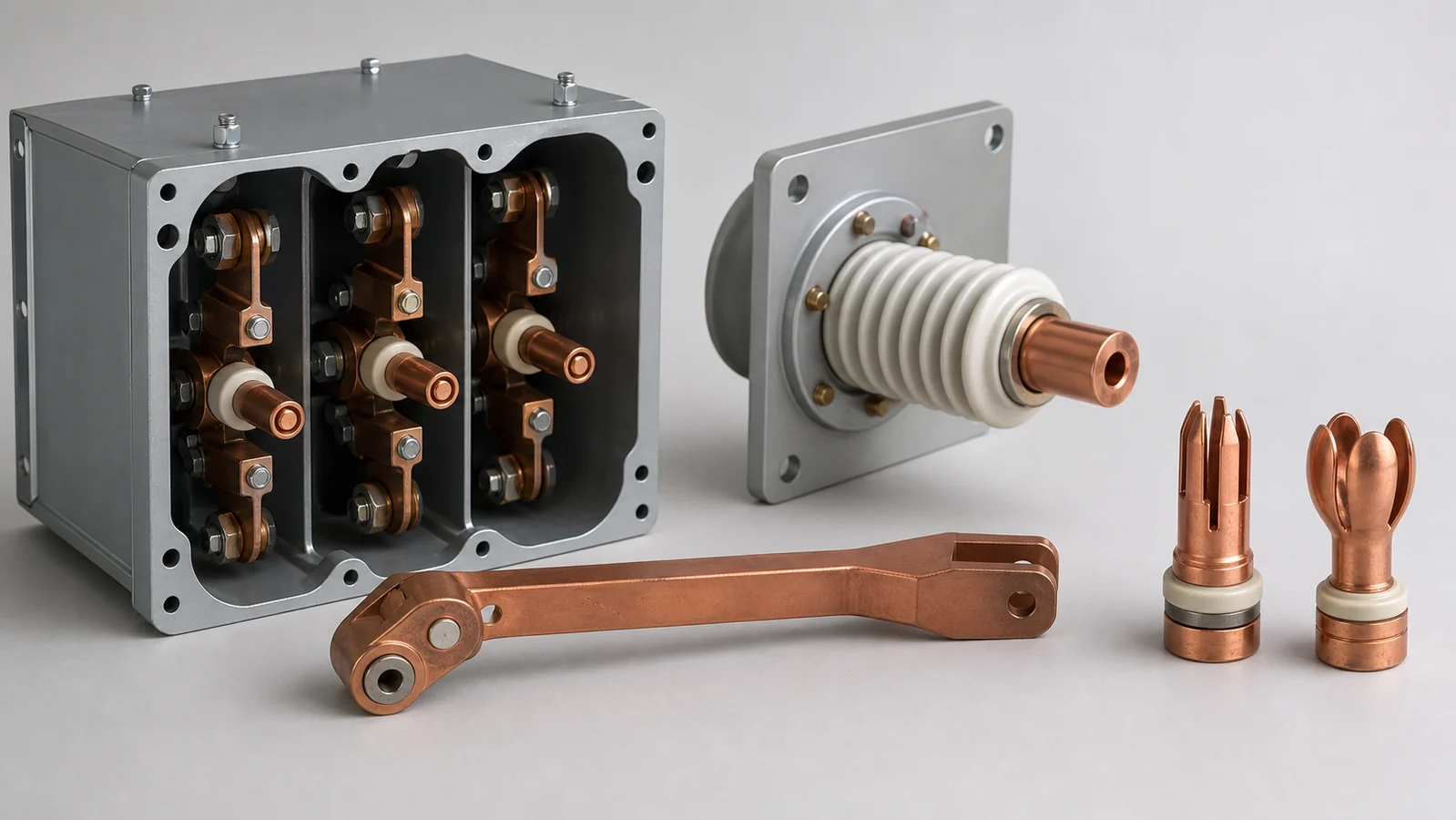
The current path zone is where the withdrawable breaker unit physically docks with the fixed cabinet structure. The contact arm extends from the breaker body and mates with the tulip contact—a spring-loaded multi-finger cluster designed to maintain low contact resistance under normal load and to withstand the electromagnetic forces generated during a fault. Tulip contact condition is a primary indicator of cabinet health; pitting, spring fatigue, or silver-plating erosion directly raises contact resistance and heat.
Neither the contact arm nor the tulip contact is a wear-neutral item. Both accumulate mechanical and electrical degradation across switching cycles and must be assessed against the breaker manufacturer’s rated mechanical and electrical endurance figures.
The earthing zone provides the safety function that allows personnel to work on the cable side of the switchgear after the circuit breaker has been withdrawn. The earthing mechanism typically consists of a manually or motorised-driven switch that connects the outgoing cable conductors to the cabinet earth bar. Mechanical interlocks—shafts, cams, and position sensors—physically prevent the earthing switch from closing while the circuit breaker is in the connected position, and prevent the breaker from being inserted while the earth switch is closed.
Interlock components are not interchangeable across cabinet designs even when they appear dimensionally similar. The interlock geometry is integral to the cabinet’s safety sequence, and substituting an unapproved part can silently defeat the intended mis-operation prevention.
The control zone contains low-voltage components that bridge the primary circuit and the external protection and control system. The secondary plug is a multi-pin connector that transfers auxiliary circuit signals—trip commands, position feedback, alarm outputs, and metering inputs—between the fixed cabinet wiring harness and the withdrawable breaker unit. Pin assignment, connector body dimensions, and current ratings vary between manufacturers and cabinet generations.
An anti-condensation heater maintains the cabinet internal temperature above the dew point, protecting insulation surfaces and contact interfaces from moisture-induced tracking. Heater sizing depends on cabinet volume, ambient temperature range, and humidity class. A heater rated for a small relay panel enclosure is not appropriate for a full-height MV cabinet compartment.
The cable compartment at the base of the cabinet terminates the outgoing MV cables and, in fuse-protected designs, houses current-limiting fuses. These fuses are rated by voltage class, breaking capacity, and let-through energy (I²t). A current-limiting fuse selected only by voltage and ampere rating without confirming the I²t characteristic and the upstream protection coordination may fail to protect downstream equipment from a through-fault.
Cable clamps and stress cones at this zone must be compatible with the cable outer diameter, insulation material, and screen termination method. These are cable-specific items, not cabinet-specific items, and must be specified against the installed cable type.
The VCB zone is the functional heart of the cabinet. The vacuum pole contains the interrupter—a pair of contacts sealed inside an evacuated ceramic or glass envelope. Arc extinction occurs by rapid dielectric recovery in the vacuum. Vacuum integrity degrades over time; the primary field check is a high-voltage withstand test across the open contacts, not a visual inspection.
The VCB’s main shaft translates the stored-energy spring mechanism’s output force to the moving contact. Trip and close coils convert an electrical signal from the protection relay into a mechanical release or charge of this spring. Coil voltage rating, resistance, and minimum operate voltage must match the station battery or UPS supply characteristics.
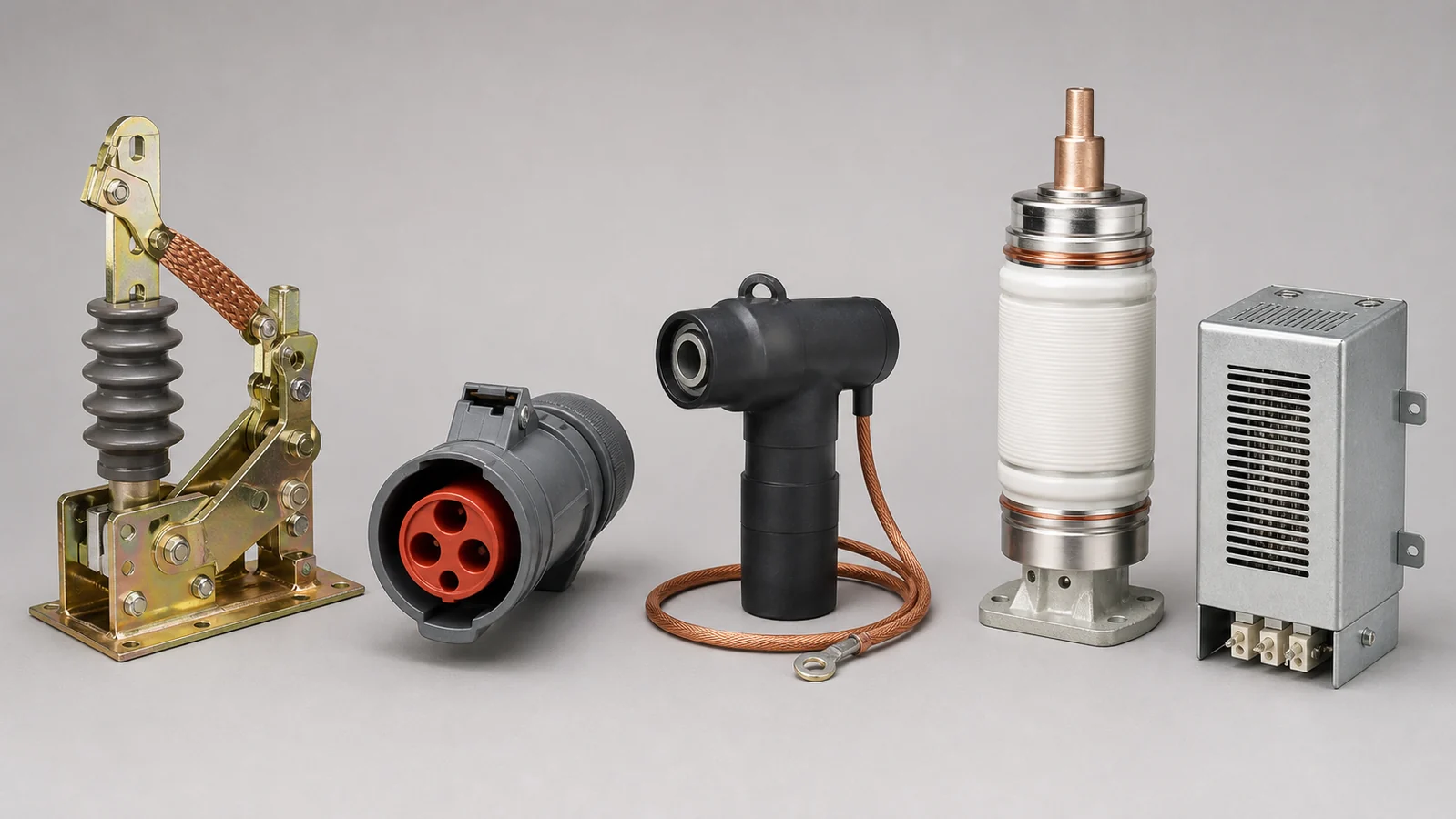
A part number, photograph, or verbal description of a component is not sufficient basis for ordering a replacement. The following evidence is required before any component can be evaluated for compatibility.
Minimum required evidence for any MV switchgear component:
Stating that a component is intended for “a KYN28 cabinet” or “a VS1 breaker” is not sufficient because both designations encompass multiple generations, manufacturers, and ratings. Compatibility must be confirmed at the drawing and rating label level, not at the type designation level. For the IEC standard governing metal-enclosed switchgear for voltages above 1 kV and up to and including 52 kV, refer to IEC 62271-200 at the IEC Webstore.
For an overview of the component families available for procurement, see the switchgear components reference page. Buyers sourcing a complete assembly rather than individual parts should review complete switchgear cabinets. For cabinet-level detail on a specific metal-clad design, the KYN28 metal-clad switchgear page provides rated specification context. Procurement of the interrupting device itself should reference the circuit breaker product section.
| Symptom | First Check | Likely Cause | Next Action |
|---|---|---|---|
| Elevated cabinet temperature in contact zone | Infrared scan of tulip contact area with breaker in service | Contact resistance increase due to silver-plating wear or spring fatigue | Withdraw breaker; measure contact resistance; compare to manufacturer’s limit; do not re-insert without assessment |
| Secondary plug arcing or signal loss | Inspect plug body and pin surfaces for carbonisation or deformation | Repeated insertion/withdrawal with live auxiliary circuits, or moisture ingress | Record pin assignment drawing; source replacement plug to exact connector specification; verify auxiliary circuit voltage before re-mating |
| Earthing switch fails to close | Check mechanical interlock position indicator and cam alignment | Interlock shaft misalignment or worn cam preventing sequence completion | Do not force the mechanism; isolate; inspect interlock geometry against cabinet drawing |
| Breaker fails to trip on protection command | Measure trip coil voltage at coil terminals during a command | Trip coil voltage below minimum operate threshold, or open-circuit coil winding | Verify station battery voltage; measure coil resistance; replace coil only with part matched to rated voltage and resistance |
| Condensation on internal insulation surfaces | Check heater operation and thermostat setpoint | Heater element failure or thermostat drift | Replace heater element rated to cabinet compartment volume; verify thermostat calibration |
| Current-limiting fuse operates recurrently | Review load profile and compare to fuse time-current characteristic | Fuse rated current too close to continuous load, or downstream fault not cleared | Coordinate fuse selection with protection engineer; confirm I²t and breaking capacity before replacement |
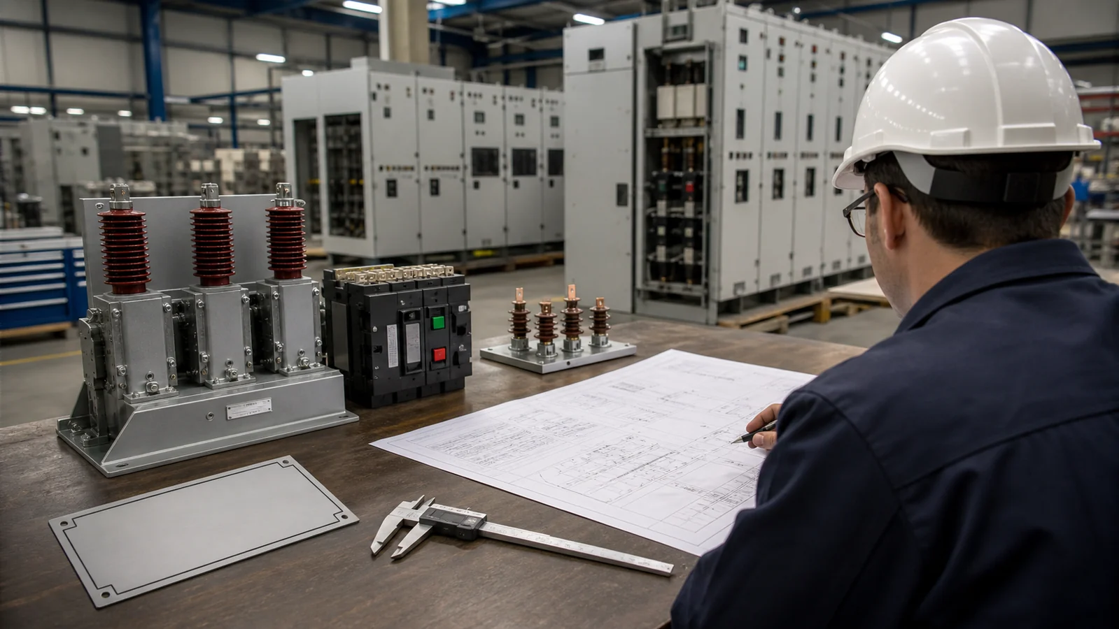
To receive a technically valid response for any medium-voltage switchgear component, submit the following information:
Submissions without rating label data and dimensional references will require a clarification cycle before any compatibility assessment can begin.
The contact arm is the moving conductor element that extends from the withdrawable circuit breaker body. The tulip contact is the fixed, spring-finger cluster mounted in the cabinet structure that receives the contact arm when the breaker is racked into the connected position. They form a matched electrical interface; each is rated to the same current and short-circuit withstand level, but they are separate components that can exhibit different wear mechanisms and must be assessed individually.
Not without additional verification. Current-limiting fuses from different manufacturers with the same voltage class and rated current may have significantly different I²t let-through energy characteristics and time-current curves. A substitution that changes these characteristics can invalidate the upstream and downstream protection coordination. Replacement requires confirmation of breaking capacity, I²t value, and compatibility with the fuse carrier and striker mechanism inside the cabinet.
You need the exact pin count, connector body dimensions, pin current rating, connector locking mechanism type, and the auxiliary circuit voltage class. The pin assignment drawing is also essential to confirm that the replacement wiring harness is compatible. Secondary plugs vary between cabinet manufacturers, cabinet generations, and even between functional variants of the same cabinet type.
Cabinet volume, compartment air circulation, ambient temperature range, and the humidity class of the installation site all determine the minimum wattage needed to maintain internal temperature above the dew point. An undersized heater allows condensation to form on insulation surfaces and contact interfaces, accelerating tracking and corrosion. An oversized heater can cause thermal stress on adjacent components. Heater selection must be matched to the specific compartment parameters, not to a generic wattage estimate.
Vacuum pole replacement involves handling the interrupter assembly, verifying vacuum integrity by high-voltage withstand testing, and confirming correct main-shaft force transmission and contact overtravel. These steps require specialised test equipment, access to manufacturer torque and travel specifications, and in most cases involvement of the circuit breaker OEM or an approved service provider. Field personnel should not attempt vacuum pole replacement without those resources and the applicable documented procedure from the circuit breaker manufacturer.



