Quotation form
Send an inquiry
Start with the basics. Our team can follow up for missing drawings, standards or packing details.
Submitted details are used only for quotation, technical review and project communication.


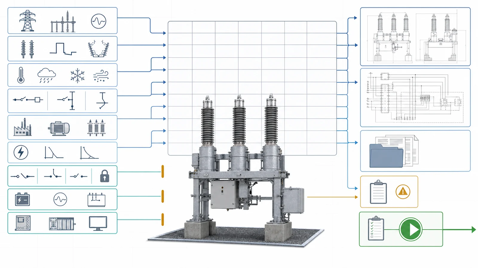
A 132 kV circuit breaker specification should be released from a coordinated requirement matrix, not from a nominal-voltage label, one fault-current figure, or a catalog model. The project must freeze the equipment class and insulation basis, convert system studies into interruption duties, define the mechanism and auxiliary supplies, coordinate protection and control interfaces, and require evidence traceable to the offered breaker.
The XIYA POWER circuit breaker range provides several high-voltage product routes. Selecting one starts only after the project inputs and evidence boundaries are clear.
Nominal system voltage opens the procurement process; it does not automatically select the highest voltage for equipment, insulation schedule, breaker family, or product rating row. Those decisions follow the purchaser’s adopted standards, insulation coordination, system studies, bay application, and service conditions.
Record open inputs explicitly instead of closing them with assumptions.
Use a selection matrix to make each required input, decision, release evidence, and hold condition visible:
| Specification question | Required input | Decision affected | Release evidence | Hold condition |
|---|---|---|---|---|
| What governs the equipment? | IEC edition, utility and project specification, precedence rules | Compliance and evidence baseline | Clause-by-clause compliance matrix | Edition or deviations are unclear |
| Which equipment class applies? | Nominal voltage, purchaser-adopted highest voltage for equipment, insulation study | Voltage class, insulation and open-gap schedule | Approved insulation schedule | Only 132 kV nominal voltage is stated |
| What are the site conditions? | Frequency, earthing, altitude, ambient, pollution, seismic, wind and ice inputs as applicable | External insulation, enclosure and structure | Service-condition schedule | Generic conditions are assumed |
| What is the bay duty? | Bay function, phase arrangement, terminal loads, foundation and layout | Product family, pole spacing and interfaces | GA and interface schedules | Bay or loads are undefined |
| What must be interrupted? | Current short-circuit and application studies | Breaking, making, short-time and special duties | Study-linked rating schedule | Study revision or scenario is missing |
| How must it operate? | Operating sequence and restoration/autoreclose philosophy | Pole and mechanism capability | Applicable design/type evidence | Sequence is treated as a catalog default |
| How is it controlled? | Trip/close architecture, supplies, CT boundary, signal and terminal lists | Mechanism, wiring and protection interfaces | Schematics and interface matrix | Ownership remains unresolved |
| What proves the offer? | Offered model, pole, mechanism and document revisions | Technical release | Reconciled evidence register | Model, drawing and evidence do not align |
The wider distribution switching equipment architecture remains the reference for device-family boundaries. A circuit breaker interrupts fault current; a disconnector or load-break device has a different duty.
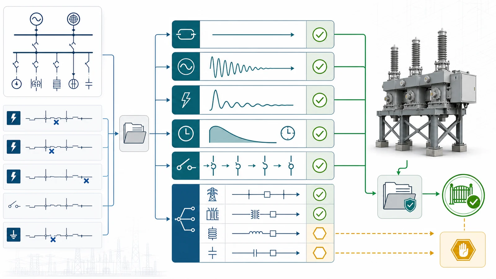
The short-circuit study must identify the breaker location, network scenario, revision, clearing basis, and future-system assumption. A fault value copied from a single-line diagram is not enough because several duties must remain separate:
Potential application duties can include terminal fault, short-line fault, out-of-phase switching, line or cable charging, transformer switching, reactor switching, or capacitor-bank switching. Not every project requires every duty. Transient recovery voltage is likewise a coordinated application and test-duty input, not a universal value to copy between projects.
The official IEC 62271-100:2021 page currently presents the 2021 base publication with its 2024 consolidated amendment information. Its public scope covers three-phase AC circuit breakers above 1 kV and states that the document includes direct making-breaking test methods, while synthetic methods are addressed in IEC 62271-101. The project must still declare its adopted edition and deviations.
| Study input | Breaker requirement | Supplier return | Hold when |
|---|---|---|---|
| Short-circuit scenario and location | Symmetrical breaking duty | Applicable type/design evidence | Study is absent or superseded |
| DC-component or X/R basis | Making/peak duty | Evidence for the declared duty | Basis is not stated |
| Fault magnitude and duration | Short-time withstand | Matching evidence | Duration is omitted |
| Restoration/autoreclose philosophy | Operating sequence | Mechanism capability and evidence | Sequence is undeclared |
| Application study | Applicable special duties | Duty-specific evidence | Duty is assumed or omitted |
| Insulation coordination | Equipment class and insulation | Insulation evidence | Equipment class is unresolved |
Product-page ratings remain model-specific examples. They demonstrate available product rows but do not become universal requirements for a 132 kV project.
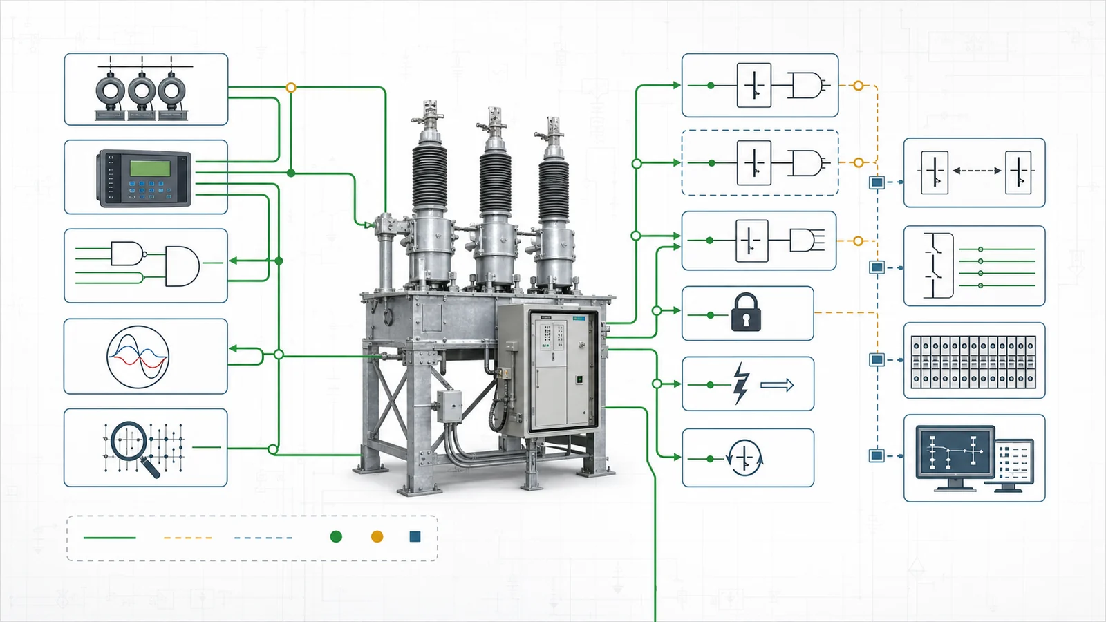
The mechanism schedule should identify one offered pole arrangement, mechanism, trip/close architecture, and auxiliary-supply package. Three-pole or single-pole operation is a project decision where applicable; the supplier should not infer it from the voltage alone.
| Mechanism question | Purchaser input | Supplier return | Release evidence |
|---|---|---|---|
| Pole operation | Required operating mode and scheme basis | Offered pole arrangement and interlocks | GA and mechanism specification |
| Mechanism route | Operating sequence and duty | Mechanism identity and principle | Applicable evidence for the offered revision |
| Trip architecture | Number and independence of trip circuits/coils | Coil, isolation, supervision and terminal data | Schematic and terminal schedule |
| Close control | Command, anti-pumping and trip-free requirements | Functional description | Wiring and functional record |
| Auxiliary supplies | Nominal supplies, permissible ranges and segregation | Motor, charger, heater, lighting and burden data | Supply and MCB/fuse schedule |
| Indication and supervision | Required position, alarm, lock and maintenance signals | Contact allocation and supervision method | Signal and auxiliary-contact list |
Where independent trip circuits are required, the project should also control their supplies, protection, cabling, terminals, and supervision. Position indication, operation counter, pole discrepancy, local/remote selection, manual or emergency operation, interlocks, maintenance isolation, and gas pressure or density supervision where applicable should be declared rather than left to a generic data sheet.
Manufacturer data must identify the offered model, pole arrangement, mechanism, and revision. A family brochure cannot close a mechanism schedule when the project-specific supply ranges, burdens, contacts, and wiring remain open.
The breaker interrupts current when commanded; the protection and control design decides when and how the command is issued. The interface matrix should assign ownership without turning the equipment specification into a relay-setting document.
| Function | Project/protection input | Breaker-supplier return | Release check |
|---|---|---|---|
| CT boundary | Scope, cores, ratios, classes, burdens and test/grounding requirements where applicable | Interface and terminal allocation | Drawings match the CT schedule |
| Trip and close | Command sources, independence, supply and isolation | Coil data, supervision and terminals | Consistent with mechanism schedule |
| Breaker failure | Initiate/return requirements and scheme ownership | Auxiliary-contact capability | Capability is stated; settings remain with protection |
| Autoreclose and synch-check | Command and confirmation interfaces | Close acceptance and position contacts | Contacts and supply are confirmed |
| Pole discrepancy and intertrip | Required logic interfaces and alarms | Detection/signalling capability | Signal list is complete |
| Station control | Hardwired or IEC 61850 architecture as selected by the project | Applicable interface data | Configuration ownership is agreed |
| Auxiliary contacts | Quantity, duty, segregation and spares | Contact allocation and ratings | Terminal list matches the signal schedule |
The interface package should include trip and close circuits, lockout, breaker-failure initiate/return, autoreclose, synch-check, pole discrepancy, intertripping, permissives, interlocks, local/remote control, marshalling, cable schedule, secondary grounding, test facilities, auxiliary contacts, and signal naming as applicable.
Protection settings, CT calculation outputs, trip times, autoreclose dead times, and relay logic values remain controlled by the protection study. The breaker supplier confirms equipment capability, burdens, contact duties, and interface timing information needed by that study.
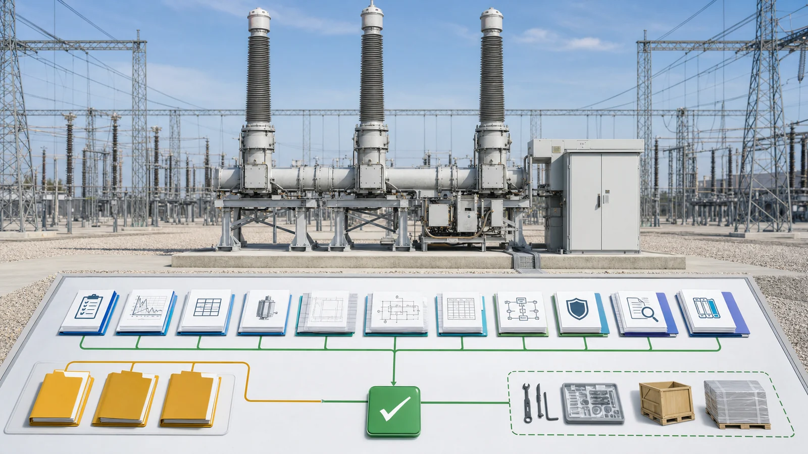
The bounded RFQ checklist should connect every requirement to one supplier response, controlled document, deviation, or hold point:
Evidence applicability matters. A GA does not prove the protection interface. A wiring diagram does not prove interruption duty. A generic type-test record does not automatically cover another voltage class, pole, mechanism, or drawing revision.
For procurement discipline, the outdoor disconnect switch RFQ checklist shows how inputs and evidence can be controlled, but it covers a disconnector. The 33-132 kV disconnect switch specification owns the isolation-device boundary; its ratings do not transfer to a circuit breaker.
Representative engineering review, not a XIYA POWER customer project, factory case, field record, commissioned installation, or service result.
An EPC requests an outdoor breaker for a 132 kV line bay. The nominal voltage is given, but the purchaser-adopted equipment class, governing edition, and insulation-coordination output are not. A fault-level value appears on the single-line diagram, while the study revision, scenario, making/peak basis, short-time duration, DC-component or X/R basis, and applicable switching duties are missing.
The protection diagram shows trip, close, autoreclose, synch-check, and breaker-failure functions. It does not define trip-coil independence, supply range, auxiliary-contact duty, pole-discrepancy interface, CT boundary, intertrip, supervision, or terminal allocation. A supplier rating sheet and mechanism drawing are attached, but their model and revisions are not reconciled with the GA, wiring package, and test evidence.
Decision: hold technical release. The review should:
No rating, mechanism, setting, passed test, shipment, commissioning result, or field performance is invented in this example. To submit a reviewable line-bay inquiry, contact XIYA POWER with the one-line diagram, study basis, specifications, interface schedules, quantity, and destination.
Include the standard hierarchy, adopted equipment class, insulation and service basis, study-defined interruption duties, operating sequence, mechanism and supplies, protection/CT/control interfaces, physical interfaces, applicable evidence, deviations, and controlled documents.
No. The purchaser must declare the adopted highest voltage for equipment and insulation basis. Nominal voltage alone does not select the rating row.
No. Also declare making/peak duty, short-time magnitude and duration, operating sequence, and each applicable special switching duty from current studies.
Specify pole operation, trip-circuit independence, close/control functions, supply ranges, burdens, supervision, interlocks, indication, auxiliary contacts, and required operating sequence. The supplier identifies the offered mechanism.
Use an ownership matrix for CTs, trip/close commands, breaker failure, autoreclose, synch-check, pole discrepancy, intertrip, auxiliary contacts, marshalling, terminals, and communication. Settings remain with the protection design.
Close study inputs, compliance and deviations, offered-model data, coordinated drawings, applicable design/type evidence, routine and FAT requirements, logistics documents, and a revision-controlled document register.



