Quotation form
Send an inquiry
Start with the basics. Our team can follow up for missing drawings, standards or packing details.
Submitted details are used only for quotation, technical review and project communication.

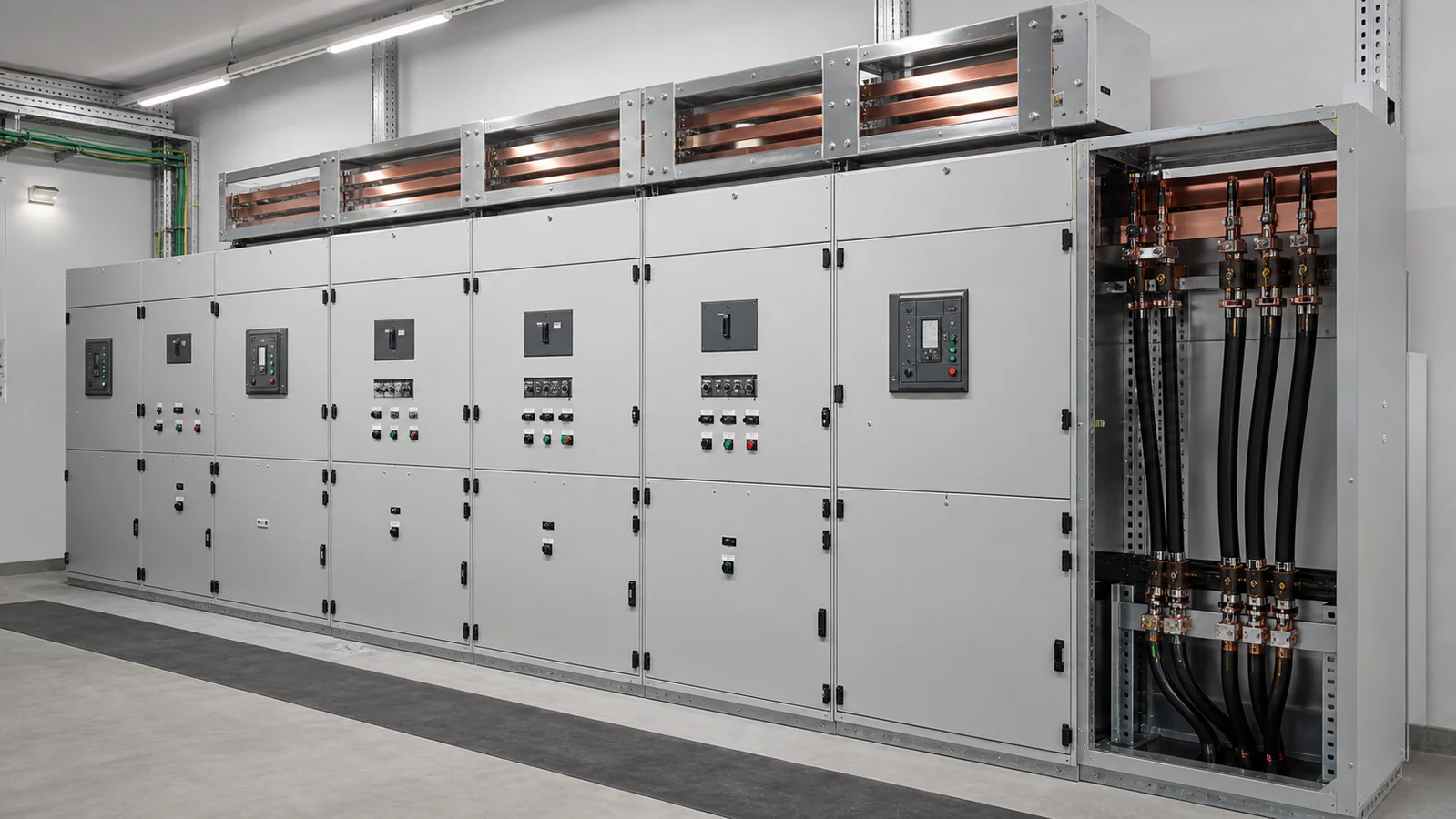
Distribution switchgear is the equipment that controls, protects, and isolates electrical circuits between a supply source and the loads it serves. In a distribution system, it decides where power can flow, provides a defined isolation point for work, and limits the effect of faults when a circuit does not operate normally.
The term covers more than one voltage class and more than one product. It can describe LV boards inside an industrial facility, MV panels in a substation, feeder switching equipment on a distribution network, or a compact ring-main unit. The correct equipment depends on the system voltage, network arrangement, fault level, operating duty, installation environment, and the protection scheme around it.
This guide gives a practical starting point: first separate the three electrical duties, then identify the equipment family, then collect the project data needed for a real selection.
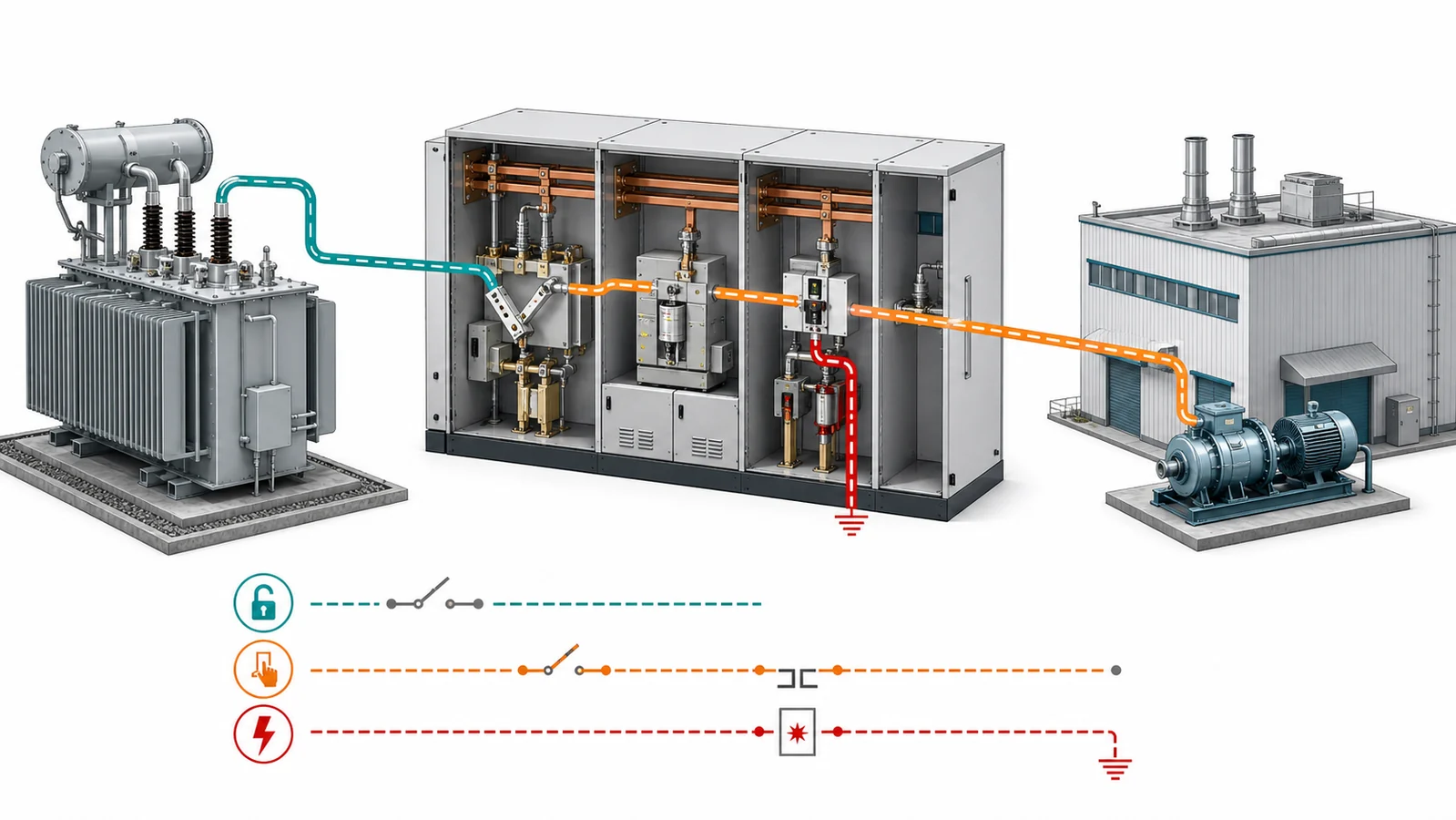
Most specification mistakes begin when isolation, normal load switching, and fault interruption are treated as the same function. They are related, but they are not interchangeable.
Isolation creates a clear separation between equipment and an energized source so that maintenance or inspection can be performed under the approved site safety procedure. A disconnector or isolator normally provides this visible or defined isolation duty after current has already been interrupted by another suitable device. It is not automatically a fault-interrupting device.
Load switching opens or closes a circuit under its stated normal operating conditions. A load break switch can be designed and tested to make and interrupt load current within its defined rating. That does not mean it can clear an arbitrary short circuit.
Fault interruption clears overcurrent or fault current before the fault damages equipment or spreads through the network. Circuit breakers and correctly coordinated fuses perform this role. Their fault duty must match the calculated prospective fault current, system voltage, and coordination study.
A complete assembly can combine these duties. For example, an MV feeder panel may include a circuit breaker for protection, disconnecting and earthing functions for safe access, relays for detection, and busbars for distribution. The selection must still be based on the duty assigned to each device, not on a broad label such as “switchgear.”
Distribution switchgear is used from the utility or industrial supply interface down to the final distribution circuits. The exact voltage boundaries differ by country, utility rules, and standards, but the common structure is straightforward:
The number of switching levels depends on the size and resilience requirements of the installation. A small compact substation may use an RMU and transformer protection unit. A process plant may require an MV lineup with several incomers, bus sections, metering, protection relays, and outgoing feeder panels. Neither arrangement is inherently better; each responds to a different network and operating requirement.
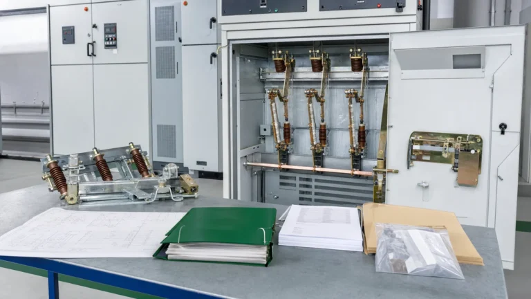
MV metal-enclosed switchgear is an assembly containing one or more functional units. Depending on the design, a unit can contain a vacuum circuit breaker, load break switch, disconnector, earthing switch, fuse combination, instrument transformers, protection relay, control equipment, and busbar connections.
An RMU is a compact MV assembly commonly used on cable distribution networks, including ring or radial arrangements. A typical configuration may provide incoming and outgoing feeder ways plus a protected transformer way. The actual number of ways, switching devices, insulation medium, and protection arrangement must follow the approved single-line diagram rather than a generic RMU description.
Air-insulated, gas-insulated, and solid-insulated designs have different service, footprint, environmental, maintenance, and end-of-life considerations. A sealed design may reduce exposed insulation space, while an air-insulated arrangement may offer a different inspection or service approach. The installation environment, required continuity of service, permitted maintenance practices, and local environmental requirements determine the appropriate route.
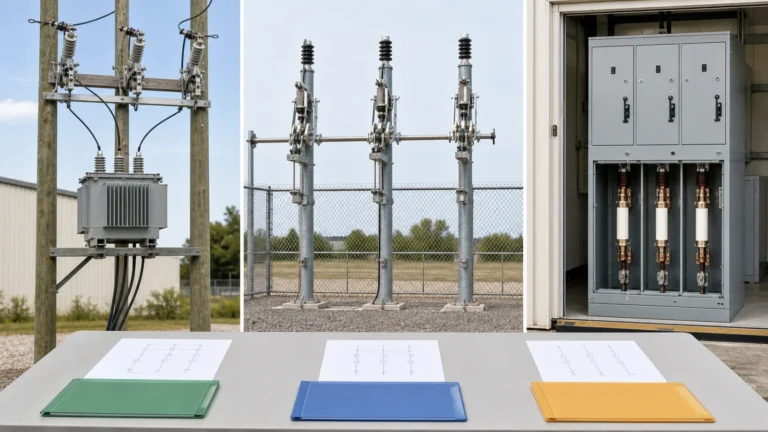
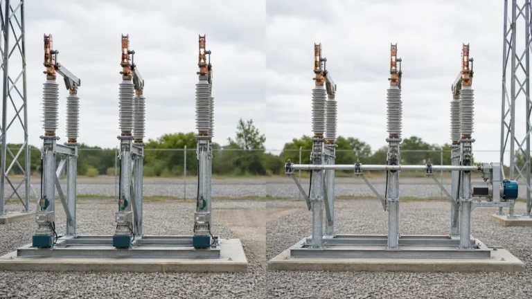
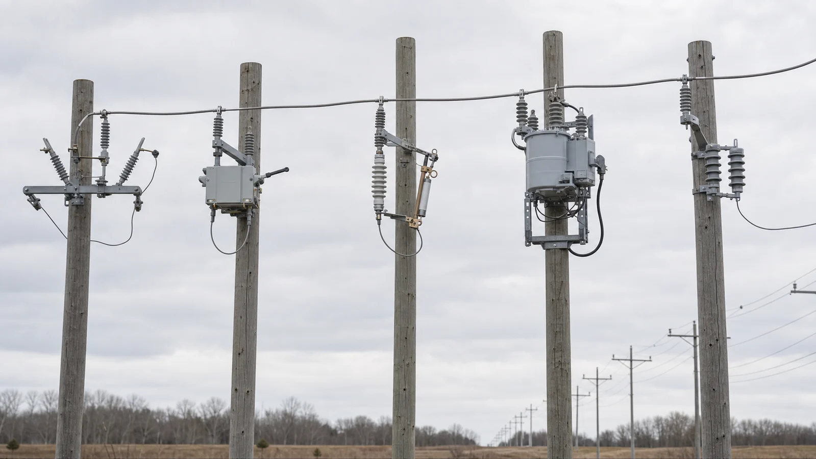
Outdoor disconnect switches, air break switches, load break switches, fuse cutouts, reclosers, and surge arresters are placed on overhead lines, at substations, and around transformer or feeder interfaces. They should be chosen by network role:
These devices often work together. The design question is therefore not “which device is best?” It is “what must this location isolate, switch, protect, or automatically restore?”
At the LV level, switchgear assemblies distribute transformer or generator output to downstream loads. Depending on the duty, the assembly can include air circuit breakers, molded-case circuit breakers, miniature circuit breakers, switching devices, busbars, metering, surge protection, and control equipment. The assembly, protective devices, enclosure, and busbar system need to be considered together; a breaker rating alone does not define the suitability of the complete board.
Modern MV systems commonly use numerical protection relays, current transformers, voltage transformers, trip circuits, metering, and communication interfaces alongside the primary switching device. These secondary systems are not optional add-ons after the main cabinet has been selected. They determine how a fault is detected, which device trips, what information is recorded, and whether the installation interfaces with a SCADA or other supervisory system.
The table below is a planning aid. It identifies questions that narrow the equipment route; it is not a substitute for a short-circuit calculation, protection study, or approved project specification.
| Project condition | Initial equipment direction | Data that still needs confirmation |
|---|---|---|
| An isolated section must be made safe for maintenance | Disconnector or isolator in the approved switching sequence | System voltage, installation type, interlock and earthing requirements |
| A circuit must be switched under normal load | Load break switch or a suitable switching device | Load type, current, switching duty, operating mechanism |
| A feeder fault must be interrupted | Circuit breaker, fuse, or coordinated protective arrangement | Prospective fault current, clearing time, protection coordination |
| A compact MV cable network has feeder and transformer ways | RMU or compact MV assembly | Single-line diagram, number of ways, protection route, cable interfaces |
| A site needs multiple MV incomers and controlled feeder circuits | MV switchgear lineup | Busbar arrangement, continuity requirement, protection, access and arc-performance requirements |
| An outdoor line needs sectionalizing or automated restoration | Outdoor switching device or recloser system | Network topology, control power, communications, protection philosophy |
Every switchgear quotation needs enough data to establish the system and equipment boundaries. The most important entries normally include:
An assembly should be reviewed as a coordinated system. A high continuous-current busbar does not by itself establish the fault performance of a feeder. Likewise, a breaker may have a suitable interruption rating while the overall lineup still requires confirmation of busbar, cable interface, protection, and mechanical arrangement.
For MV metal-enclosed assemblies, IEC 62271-200 identifies the standard scope for AC assemblies above 1 kV and up to 52 kV. The project specification and applicable local requirements still determine which ratings, tests, classifications, and documents apply to an individual order.
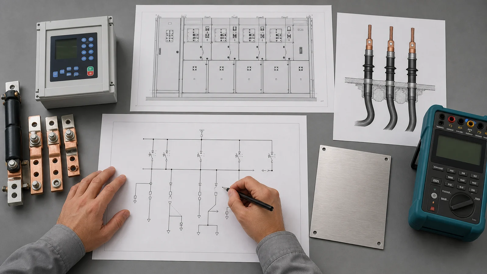
The first selection discussion is based on design information, not a claim that the equipment has already passed a particular project test. The table below separates the usual input from its role in the review.
| Input or acceptance source | Why it matters | Typical review owner |
|---|---|---|
| Single-line diagram | Defines the source, busbar, feeder, and isolation arrangement | Project electrical engineer |
| Project specification | Sets voltage, standards, service conditions, and customer requirements | Buyer and technical reviewer |
| Manufacturer data sheet | Confirms declared device and assembly characteristics | Manufacturer technical team |
| Protection study | Establishes fault level, settings, and coordination requirements | Protection engineer |
| Approved drawing | Confirms layout, cable entry, terminals, and interfaces before manufacture | Buyer and manufacturer |
| FAT procedure or test record, where released | Confirms the agreed inspection and test scope for the order | Buyer and manufacturer quality teams |
This is an acceptance-source list, not a substitute for the project approval route. A multimeter, insulation tester, contact-resistance instrument, or timing analyzer may be used within an approved inspection procedure, but the required test method and acceptance criteria must come from the applicable project specification, product documentation, and agreed test plan.
Switchgear selection is linked to several upstream engineering decisions:
Collecting this information early reduces later drawing revisions and avoids selecting a device based only on voltage and current.
No. A disconnect switch primarily provides isolation. A circuit breaker is selected for specified interruption duties, including fault interruption where its rating and protection scheme require it. Some assemblies include both functions, but the devices perform different jobs.
Only where the project protection scheme does not require the switch to clear fault current. A load break switch must be applied within its declared normal-current switching and making duties. Fault protection can require a breaker, fuse, or another coordinated protective device.
No. RMUs can use different insulation approaches. The chosen construction should be matched to the network arrangement, site conditions, maintenance plan, available footprint, environmental policy, and required documentation.
Start with the single-line diagram, system voltage and frequency, continuous current, available fault current, number of functional units, installation environment, protection requirements, cable interfaces, and applicable standard or utility requirements.
No. The nameplate is an essential starting point, but the selected assembly also has to match the single-line diagram, fault level, protection arrangement, busbar and cable interfaces, service conditions, access requirements, and the approved project specification.
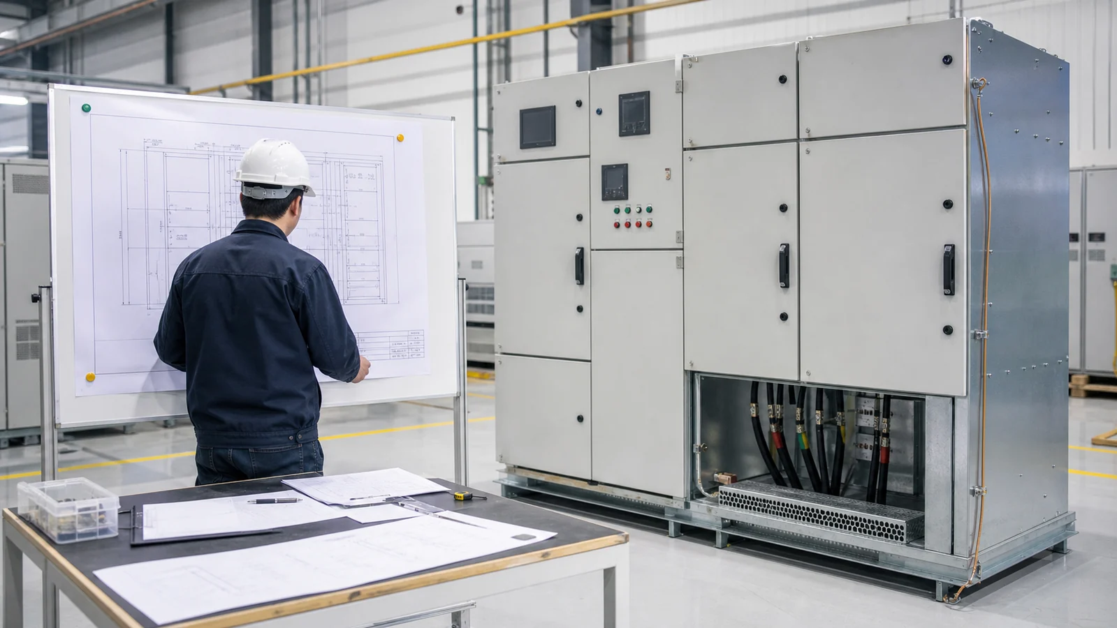
For a meaningful quotation or technical review, prepare the single-line diagram and list the voltage, frequency, incoming and outgoing current, prospective short-circuit level, number of panels or ways, cable entry, protection functions, control/communication needs, installation environment, and governing standards. These inputs let a supplier match the switchgear configuration to the project rather than offer a generic catalog item.
For the relevant equipment families, see XIYA POWER distribution switching equipment. A detailed selection should then be checked against the project calculation, approved drawings, and operating requirements.