Quotation form
Send an inquiry
Start with the basics. Our team can follow up for missing drawings, standards or packing details.
Submitted details are used only for quotation, technical review and project communication.

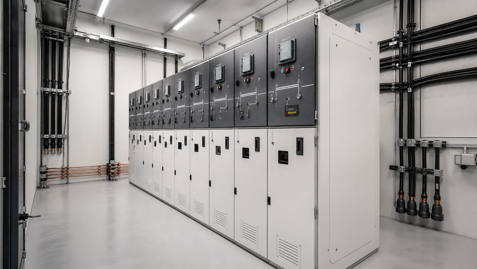
A ring main unit (RMU) is a compact, factory-assembled medium-voltage switchgear assembly designed to connect a distribution transformer or outgoing feeder into a cable ring circuit while supporting network continuity. At secondary distribution level, the selected RMU can provide load switching and the specified transformer or feeder protection functions within a compact enclosure. The voltage class, installation form, and protection arrangement are selected for the project rather than inferred from the generic RMU name.
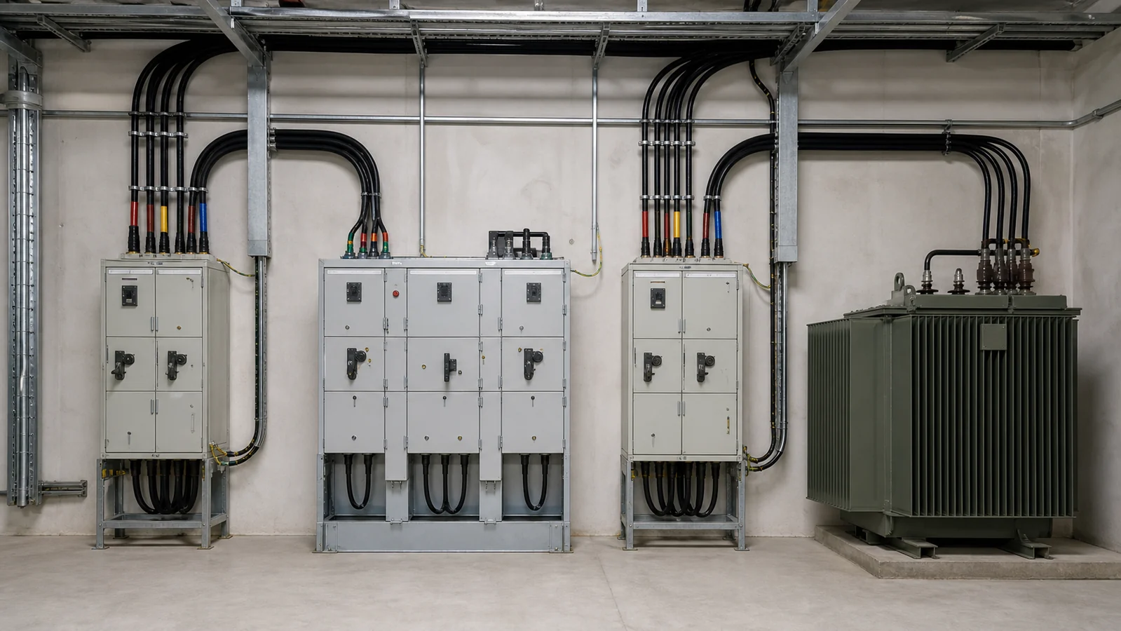
Primary substations receive power at transmission voltage and step it down to medium voltage (MV). That MV voltage is then distributed across a network of underground cables arranged—where supply reliability matters—in a ring topology. Each point of supply along the ring is served by an RMU.
The ring topology offers a critical operational advantage: if a cable section develops a fault, network operators can open two switches to isolate the faulted section, then close normally-open points elsewhere in the ring to restore supply to every customer except those directly connected to the faulted cable. Without the switching capability that an RMU provides at each ring node, this isolation and restoration sequence cannot be executed selectively.
Secondary distribution in dense urban areas, commercial campuses, industrial parks, and renewable energy collector systems all rely on this principle. An RMU therefore performs three simultaneous roles:
Modern RMUs are built from standardized functional modules. The module labels C, F, V, and CB each identify a distinct duty; no single installation will necessarily use all four, and the sequence in which modules appear in a lineup varies by network design.
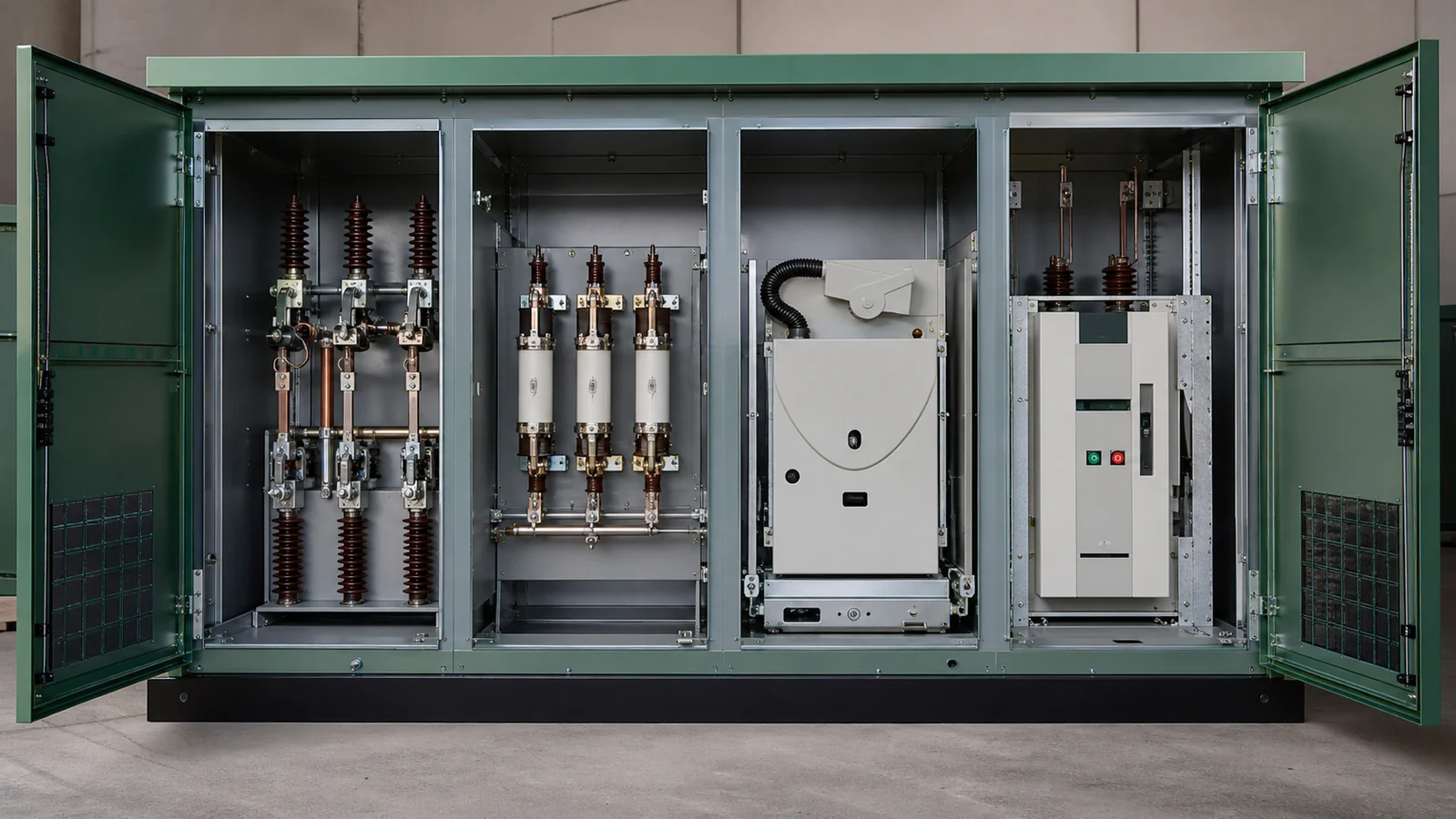
The C (cable) module commonly contains a load break switch rated for the declared normal load-current switching duty. The short-circuit making duty, where required, must be confirmed for the selected module. Two C modules are a common ring-through arrangement: one connects to an incoming cable and the other to an outgoing cable. Under normal operation both switches may be closed; an approved switching plan can isolate a cable section and restore supply from the opposite direction where the network topology permits it.
Load break switches used in this position must satisfy both load-current and short-circuit making duties. For further context on the switch type used at this position, see load break switch selection guidance.
The F module pairs a load break switch with high-voltage fuses on the outgoing side, typically feeding a distribution transformer. The switch provides load-current switching and back-up isolation; the fuses provide overcurrent and fault protection for the transformer without requiring an active protection relay. This combination is cost-effective for transformer ratings where the fault energy is within fuse-interrupt capability. F modules do not provide the same degree of protection selectivity as relay-controlled breakers and are not suited to every network protection philosophy.
The V module replaces the fuse with a vacuum interrupter capable of fault interruption. Combined with a protection relay and current transformers, a V module can interrupt short-circuit current and be trip-commanded by overcurrent, earth-fault, or directional protection functions. This makes the V module appropriate for outgoing feeders where protection coordination with upstream devices is required, or where the fault level exceeds fuse interrupt ratings.
Some RMU designs incorporate a dedicated circuit breaker (CB) module with its own mechanism and interruption technology. It may be specified where the project protection scheme calls for the required relay integration, operating sequence, or other circuit-breaker functions. Confirm interruption endurance, auto-reclose capability, and maintenance requirements for the selected model rather than assuming them from the module label.
Not every manufacturer assigns the same label to each module type; project specifications should define the required functional duties explicitly rather than relying on label conventions alone.
Maintaining ring continuity is an operational requirement, not merely a design feature. RMU enclosures incorporate mechanical and, in some designs, electrical interlocks to prevent unsafe operating sequences—for example, preventing a busbar earth switch from closing while a ring switch is closed, or preventing a panel door from opening before a local earth is applied. Interlock logic varies by design family and must be verified against the project’s switching procedures.
Cable interfaces on RMUs are typically plug-in or bolted elbow connectors compatible with the cable system voltage class. Some designs support live-front or dead-front cable termination, which affects the extent of work permitted under energized-adjacent conditions.
No single insulation technology is universally superior. Each family involves trade-offs that make it more or less suitable depending on environment, maintenance access, footprint, and local regulations.
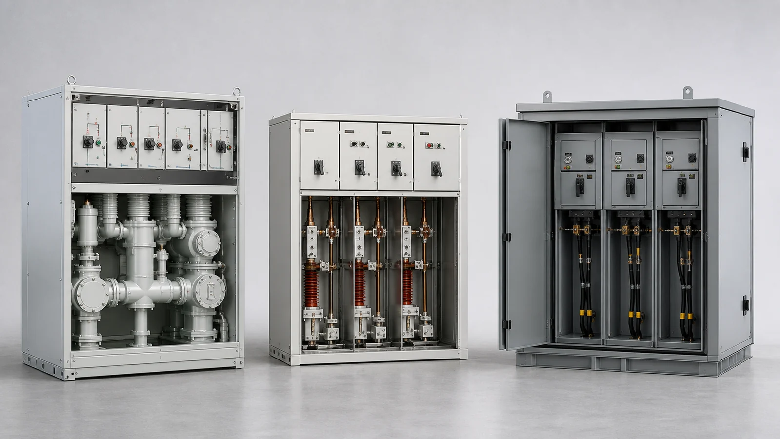
| Construction Family | Insulating Medium | Characteristics Relevant to Project Selection |
|---|---|---|
| SF₆ gas-insulated | Sulfur hexafluoride gas | Long-established arc-quench performance; SF₆ is a potent greenhouse gas subject to F-gas regulations in multiple jurisdictions; gas-pressure monitoring required; hermetically sealed designs reduce but do not eliminate leak risk |
| Solid-insulated (SIS) | Cast epoxy or polymer resin | No gas handling; enclosure can be smaller; arc performance depends on resin quality and design; suited to environments where gas handling is not permitted or practical |
| Common-box / air-insulated | Air within a sealed metallic enclosure | Proven technology; enclosure size tends to be larger; suitable for drier climates and applications where physical footprint is not constrained |
| Alternative gas (e.g., N₂, dry air, g³) | Nitrogen, dry air, or proprietary blends | Emerging as SF₆ alternatives; project teams should verify rated performance at the applicable fault level and temperature range |
Project engineers selecting an insulation family should reference the applicable IEC standard—IEC 62271-200 covers AC metal-enclosed switchgear and controlgear for rated voltages above 1 kV—and confirm that the selected equipment meets the Loss of Service Continuity (LSC) and Partition (P) classifications required by the network owner.
For a range of RMU models with specific voltage, current, and short-circuit ratings, the XIYA RMU product page lists model-specific values that should be reviewed during selection. Do not apply those figures as generic RMU ratings; treat each as a data point for that specific product variant.
The following table supports initial assessment of RMU operational anomalies. It does not replace utility switching procedures, network operator authorization, or arc-flash risk assessment. No switching or test actions should be taken without proper authorization and personal protective equipment.
| Symptom | First Safe Test / Observation | Likely Cause | Recommended Next Action |
|---|---|---|---|
| Loss of supply on transformer feeder, ring sections energized | Check F or V module trip indicator; inspect relay event log if fitted | Overcurrent or earth-fault trip on outgoing module | Confirm fault cleared; arrange authorized re-energization via switching schedule |
| Persistent gas-pressure alarm on SF₆ RMU | Read pressure gauge at safe distance; do not operate switching devices | SF₆ leak or pressure transducer fault | Remove from service; arrange gas analysis and leak test by qualified personnel |
| Cannot close ring switch mechanically | Check interlock state; verify adjacent earth switch position | Interlock engaged due to earth switch closed or door open | Follow interlock release procedure in manufacturer’s manual under authorization |
| Protection relay indication with no apparent feeder fault | Review relay event record; check CT wiring for continuity | CT open circuit, relay setting error, or external transient | Do not reset until event log reviewed; involve protection engineer |
| Unusual noise or burning odor from enclosure | Do not open; evacuate non-essential personnel | Internal arc or failing contact | Implement emergency isolation procedure; contact switchgear specialist before re-entry |
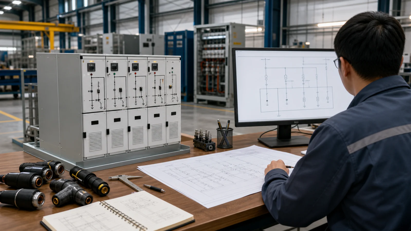
When preparing a request for quotation for an RMU, provide the following minimum data to enable accurate equipment selection:
Review the complete switchgear cabinet range and switchgear components pages for complementary equipment that may be specified alongside an RMU.
RMUs are designed for medium-voltage secondary distribution, most commonly at system voltages between 6 kV and 36 kV. The exact rated voltage of a specific RMU must be confirmed against the manufacturer’s nameplate data and the relevant IEC rating standard. Higher-voltage primary switchgear serves a different network position and is not an RMU in the secondary-distribution sense.
This depends on the module type fitted. A C module (ring-feed switch) switches load current and can make onto a fault, but is not rated to break fault current. An F module delegates fault interruption to the fuses. A V or CB module, when combined with a protection relay and current transformers, can detect and interrupt fault current. Specifying the correct module type for each position is essential to achieving the protection performance the network requires.
Gas-insulated RMUs use SF₆ or an alternative gas as the arc-quenching and insulating medium inside a sealed enclosure. Solid-insulated RMUs use cast epoxy or polymer resin to encapsulate live parts. The two technologies can achieve similar electrical performance but differ in gas-handling obligations, enclosure size, environmental compliance requirements, and long-term maintenance considerations. Neither is universally superior; project constraints determine which is appropriate.
Under normal operation, both ring switches in an RMU are closed, and load current flows through the ring continuously. If a cable section faults, the two RMUs at either end of that section open their respective ring switches, isolating only the faulted cable. Supply to all other points on the ring is maintained from the opposite direction. This selective isolation is the operational purpose of the ring topology and depends on each RMU being capable of independent switching.
IEC 62271-200, AC metal-enclosed switchgear and controlgear for rated voltages above 1 kV and up to and including 52 kV, is the primary design and type-test standard applicable to the metal-enclosed construction used in most RMUs. It defines LSC categories, partition classes, arc-fault classifications, and routine test requirements. Procurement specifications should state the applicable edition and any additional national deviations required by the network owner.