Quotation form
Send an inquiry
Start with the basics. Our team can follow up for missing drawings, standards or packing details.
Submitted details are used only for quotation, technical review and project communication.

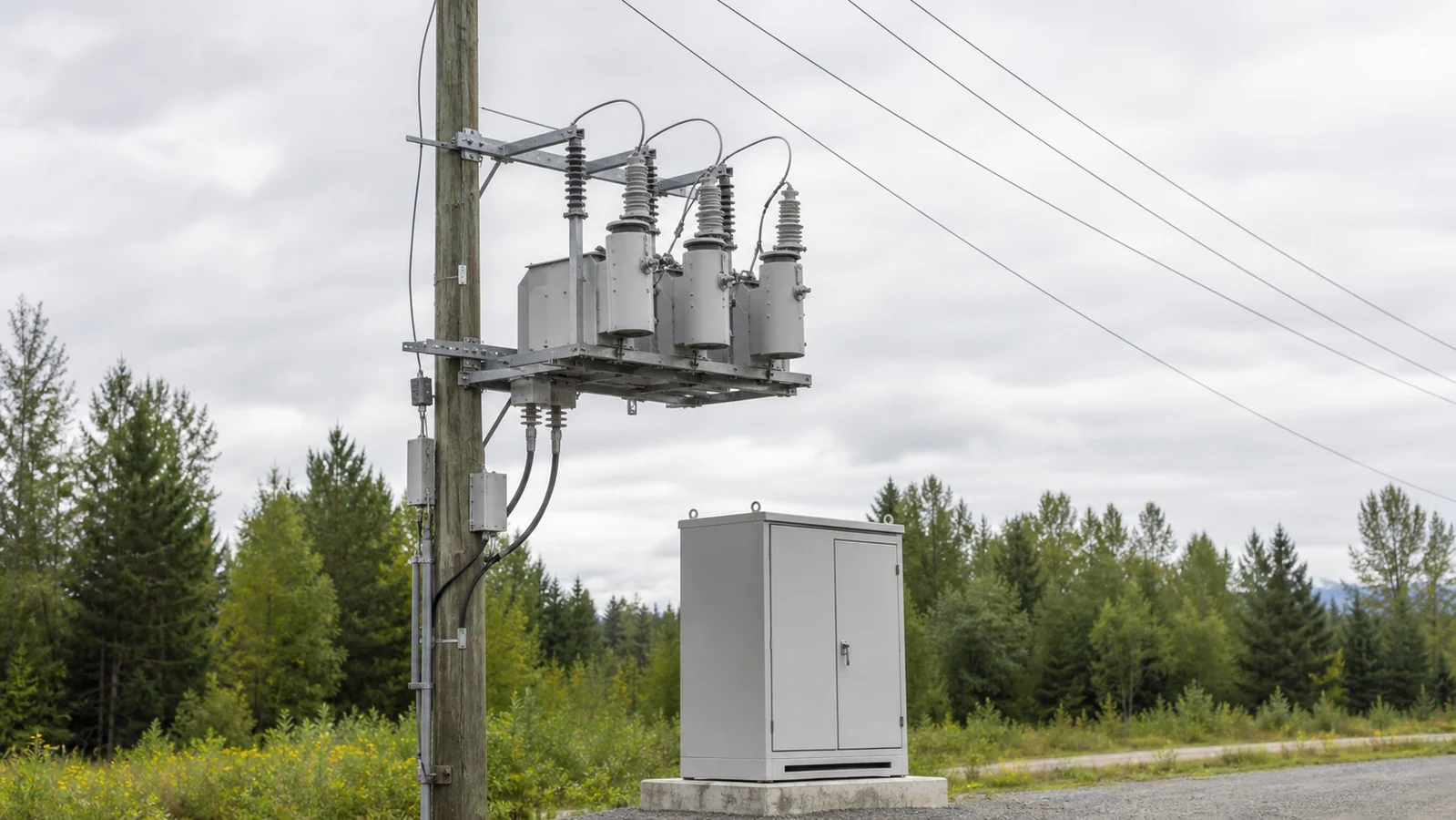
A recloser is an automatic distribution switching and protection device engineered to interrupt specified fault currents and execute a programmed sequence of reclose attempts and, when required, lockout. Installed at strategic points on overhead feeders — substation exits, mid-line sectionalizing points, or lateral taps — it operates without human intervention during the critical seconds after a fault, sustaining supply when the cause is transient and holding the line open when the fault is permanent.
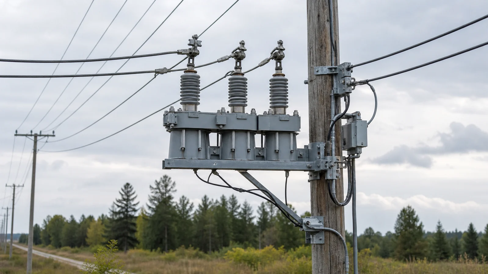
Figure 1. Recloser mounted at a mid-feeder sectionalizing point on an overhead distribution circuit.
Unlike a fuse or a manually operated switch, the recloser integrates four interdependent subsystems: the switching body that interrupts current, sensors that measure current and voltage, a controller that executes protection logic, and a communication interface that connects the device to a SCADA or distribution management system. None of these subsystems is optional; together they constitute the device. Specifying a switching body without defining the controller configuration and communication stack leaves the protection coordination incomplete.
The switching body houses the interrupter and the operating mechanism. Vacuum interrupter technology is the dominant choice for medium-voltage distribution reclosers because it provides rapid arc extinction, long mechanical life, and a compact, sealed assembly suited to outdoor, unattended service. The body must be rated for the system voltage, the continuous load current, and — critically — the interrupting current at the fault level available at the installation point.
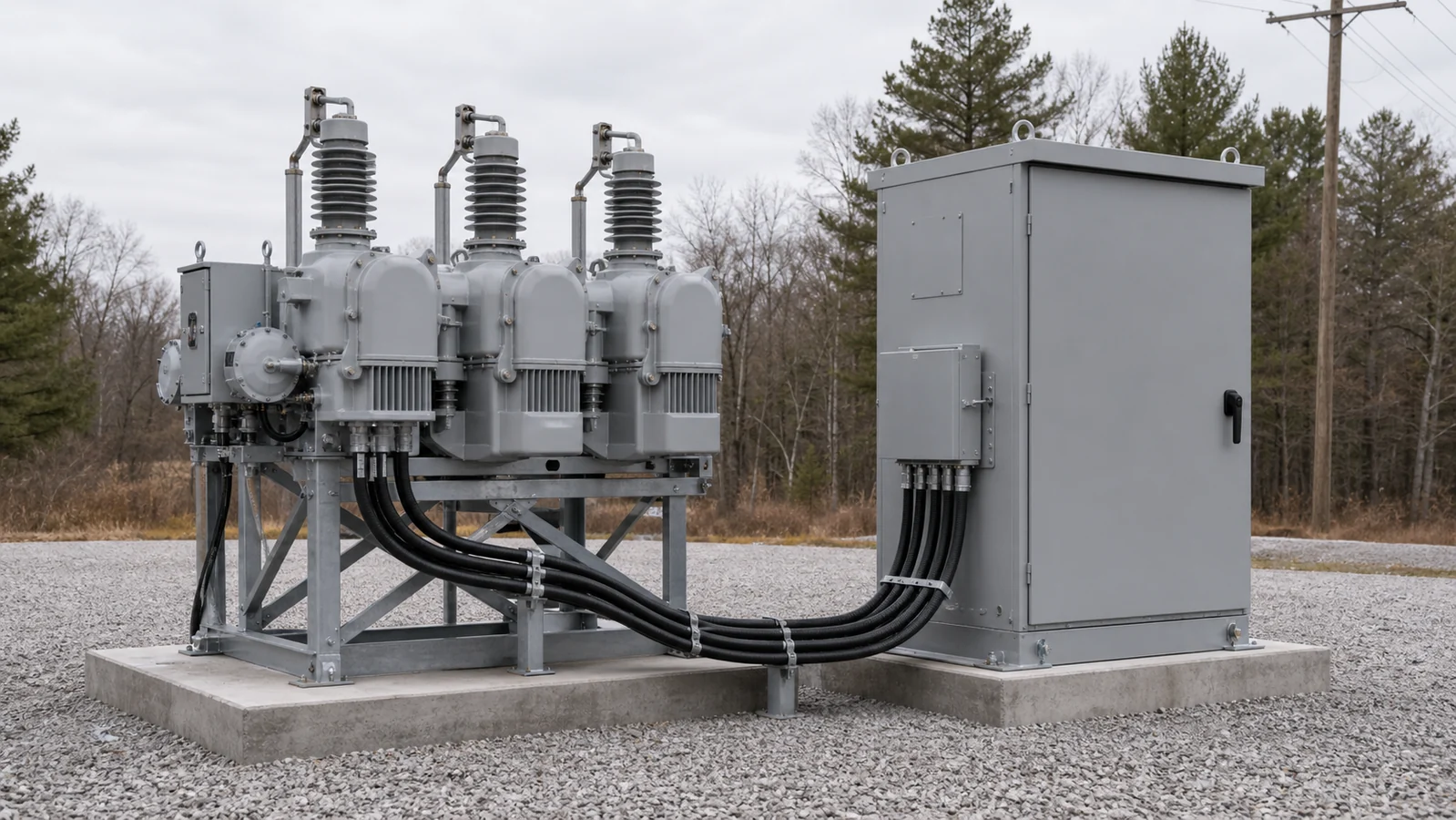
Figure 2. Recloser body with integrated current and voltage sensing, controller housing, and communication module — shown as a unified package.
Integral current transformers supply phase and ground current signals to the controller on every operating cycle. Some designs include voltage sensors on both the source and load sides, enabling live-line detection, sync-check functions, and post-fault voltage verification before a reclose attempt is issued. Without accurate sensing, the controller cannot distinguish load current from fault current, and the protection scheme degrades to an open-loop function that cannot adapt to system conditions.
The controller is the intelligence of the recloser package. It receives analog signals from the sensors, applies the selected protection curves and thresholds, determines when to trip and when to reclose, counts reclose attempts, and executes lockout when the programmed sequence is exhausted. Because reclose attempts, dead times between attempts, and the specific time-overcurrent (TOC) or instantaneous overcurrent (INST) curves assigned to each operation are all defined in the controller configuration, these parameters are project-specific. No manufacturer default should be assumed to satisfy a given feeder’s coordination requirements without a formal study.
A communication interface — IEC 61850, DNP3 over fiber or cellular, or another utility-approved protocol — connects the controller to the distribution management or SCADA platform. Remote visibility of device status, fault current magnitude, lockout indication, and reclosing enable/disable control are functions of the communication configuration, not the switching body. The automatic vacuum circuit recloser product page covers the package architecture in the context of modern smart-grid deployment.
Overhead distribution faults can be transient, for example after some temporary environmental contacts, or permanent, for example after a damaged conductor or insulator. Where a fault has cleared and the approved protection sequence permits re-energization, a reclose attempt may restore supply. The actual fault outcome and the appropriate sequence depend on feeder conditions and the protection study.
A recloser’s reclose-and-lockout sequence is designed to discriminate between these two classes. It does not guarantee a specific clearance rate for transient faults; outcomes depend on fault type, feeder length, conductor configuration, and the specific sequence programmed in the controller.
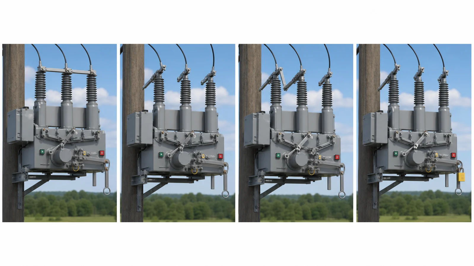
Figure 3. Conceptual protection sequence showing trip, dead time, reclose attempt, and lockout — specific operation counts and timing are controller- and project-defined.
After a trip, the controller waits a defined dead time before issuing a reclose command. If the fault has cleared, the line re-energizes and the recloser resets after a programmed reset time. If the fault persists, the device trips again and may attempt additional reclose operations — each separated by a dead time — before reaching lockout. The count of operations and the dead times between them are set in the controller to suit the feeder’s protection coordination plan; they are not fixed product characteristics.
Lockout is the condition in which the recloser has exhausted its programmed sequence and holds the line de-energized. It requires a deliberate reset — local or via SCADA — before the device will attempt to close again. Lockout protects downstream equipment from repeated fault-current exposure and signals operations personnel that a physical inspection is needed before restoration.
A recloser in a feeder coordination scheme operates in concert with fuse cutouts on laterals and other protective devices. On an initial fault operation, it may apply a fast curve intended to operate before a lateral fuse melts, preserving the fuse for permanent lateral faults. Subsequent operations may shift to a slower curve, allowing the fuse to clear a permanent lateral fault while the recloser holds closed on the main feeder. This coordination logic is defined entirely in the controller and must be engineered for each feeder topology. See the smart-grid switching and protection overview for the broader distribution automation context.
| Device | Interrupts Fault Current | Automatic Reclose | Sensing and Controller | Remote Control | Primary Role |
|---|---|---|---|---|---|
| Recloser | For the selected interruption duty | Project-programmed sequence where specified | Selected sensing and controller package | Where the selected communication package provides it | Feeder protection and automation |
| Fuse cutout | Within the compatible fuse and assembly rating | No | No controller required for fuse operation | Not as an automatic protection function | Lateral and transformer fault isolation |
| Load break switch | Not as a standalone fault-clearing device | No | Model-specific | Model-specific | Sectionalizing and load switching |
| Substation circuit breaker | For the selected breaker duty | External relay and scheme dependent | External relay and control scheme | Scheme dependent | Bus and feeder protection at substation |
A drop-out fuse provides passive, one-shot fault isolation on a lateral; it cannot reclose, cannot adapt its response between operations, and provides no electronic fault record. A medium-voltage circuit breaker operates within a switchgear assembly controlled by a separate protection relay and is primarily applied at substation bus and feeder breaker positions — not for autonomous mid-line distribution automation. Confusing these roles leads to misapplied equipment and coordination gaps.
Standards context: equipment classification and performance requirements for distribution reclosers are addressed in IEC 62271-111, which covers alternating-current reclosers and fault interrupters for distribution systems rated above 1 kV.
The table below is a structured first-triage guide. It does not replace utility operating procedures or manufacturer service documentation.
| Symptom | First Test | Likely Cause | Next Action |
|---|---|---|---|
| Recloser in lockout, feeder de-energized | Verify lockout indication on controller display or SCADA; retrieve fault current log | Permanent fault on protected segment | Do not reset until patrol or fault-locator data confirms the fault is clear |
| Recloser trips and recloses repeatedly without reaching lockout | Check controller event log for fault current magnitude and operation count; confirm reset timer state | Recurring transient fault or borderline permanent fault | Review fault location data; inspect overhead line for mechanical contact sources |
| Recloser fails to trip during a confirmed fault | Verify control power supply to controller; check CT secondary circuits for continuity | Loss of control power, blown control fuse, or open CT secondary | Restore control power per procedure; never bypass CT secondary |
| Recloser closes then immediately trips again | Check controller phase and ground overcurrent targets; verify source-side voltage | Fault still present, or pickup setting mismatched to load current profile | Confirm the feeder is clear before any manual close attempt; refer pickup review to protection engineer |
| Communication loss to SCADA | Check communication module status indicator; verify fiber or cellular path continuity | Communication path failure or module fault | Restore path per network procedure; local protection continues independently |
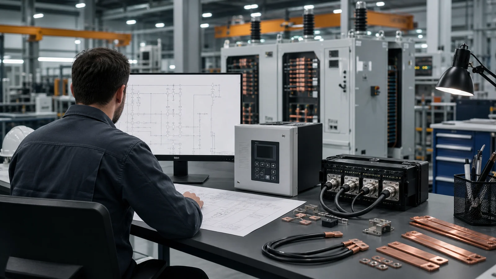
Figure 4. Engineering review stage: controller configuration and coordination study inputs reviewed against feeder topology before procurement.
Incomplete recloser specifications result in equipment that cannot be coordinated without costly field modification. Before preparing a request for quotation, define the following:
A circuit breaker is a switching and interrupting device designed to operate under the control of a separate external protection relay within a switchgear assembly. A recloser integrates the interrupter, sensing, and controller in a single outdoor-rated package intended for autonomous operation on a distribution feeder. The circuit breaker depends on external relay logic; the recloser carries its protection intelligence internally and is designed to complete its entire fault-to-lockout sequence without a control room command.
These devices serve fundamentally different coordination roles. A fuse cutout provides passive, one-shot fault isolation sized to its fuse element. A recloser provides active, programmable fault interruption with multiple operations. Substituting one for the other changes the coordination scheme for every device upstream and downstream; any such change requires a formal protection coordination study before implementation.
The reclose sequence — number of operations, dead times, and curve assignments — is stored in the controller configuration. On devices with a communication interface, authorized personnel can modify these parameters via SCADA or a local interface without removing the device from service. All changes to protection settings must follow the utility’s change management and coordination review process before being applied.
Control power sources and requirements are device- and project-specific. Common approaches include a potential transformer tapping source-side voltage, a dedicated battery with charger, or a solar-assisted supply for remote installations. The controller must remain powered through a de-energized line condition to retain fault logs, lockout state, and communication. Loss of control power is a reportable condition that may indicate a protection gap.
Through its communication interface, a recloser reports status, fault current magnitude, operation count, and lockout state to the distribution management system. It can receive remote open, close, and configuration commands within the authorization framework the utility has established. In a distribution automation application, multiple reclosers and sectionalizing switches may be coordinated to achieve automatic fault isolation and supply restoration across feeder segments — a system-level design that must be specified and studied independently of any individual device.
For equipment selection, protection coordination studies, and controller configuration, engage your protection engineering team and refer to the applicable IEC standards and utility specifications before procuring or commissioning.