Quotation form
Send an inquiry
Start with the basics. Our team can follow up for missing drawings, standards or packing details.
Submitted details are used only for quotation, technical review and project communication.

Both outdoor and indoor disconnect switches serve the same fundamental isolation role: when selected and installed for the approved duty, they establish the isolation state needed before maintenance, inspection, or reconfiguration. That shared role is the starting point for every selection conversation. What changes when the installation environment changes is the set of project inputs — enclosure material, sealing specification, operating mechanism reach, access pathway, documentation requirements, and more — that determine whether a given disconnect switch is appropriate for a specific site.
A basic disconnect switch is an isolation device. Its permitted operation must be taken from the approved equipment rating and project operating procedure; it is not inherently a load-break or fault-interrupting device. Where a circuit must be opened under load, a load break switch with the correct load-interrupting duty is required. Where overcurrent protection and isolation are both needed at the same point, a fuse disconnect switch may be appropriate. Selecting the correct device class for the actual operating duty is the first and most consequential decision a project team makes.
The electrical isolation function does not change between a substation yard and a switchroom, but every project input surrounding that function is location-sensitive. Outdoor equipment faces precipitation, humidity cycles, UV exposure, wind, ice accumulation, and wildlife; indoor equipment faces a more controlled ambient environment, generally lower contamination levels, and physical access constraints imposed by the building layout. These environmental and access differences propagate directly into enclosure type, material finish, sealing class, insulator selection, operating mechanism design, clearance requirements, foundation or panel arrangement, auxiliary wiring routing, and the content of the installation drawing package.
Because each of those project inputs is site-specific, no single construction, coating grade, voltage class, or current rating applies universally to all outdoor or all indoor installations. The appropriate equipment configuration is determined by the combination of system voltage, load-current magnitude, installation altitude, ambient temperature range, pollution severity, seismic zone, and the owner’s maintenance philosophy — all of which vary from project to project.
The following illustrative diagnostic example is a procurement prompt, not a field record or a measured test result. It helps identify the first document or action needed before a supplier is asked to configure equipment.
| Symptom or RFQ gap | First test | Likely cause | Next action |
|---|---|---|---|
| Buyer has only a voltage class and a product name | Check whether the operating duty is isolation-only | Device class and switching duty are not yet defined | Confirm the one-line diagram and operating procedure before requesting a disconnect switch quotation |
| Outdoor location is stated without environmental data | Check the project specification and site information | Pollution, temperature, altitude, or mounting exposure is unknown | Request the missing site inputs; do not use a prior project’s values as a corrective action |
This troubleshooting chart is deliberately limited to information gaps. It does not replace project engineering or an installation review.
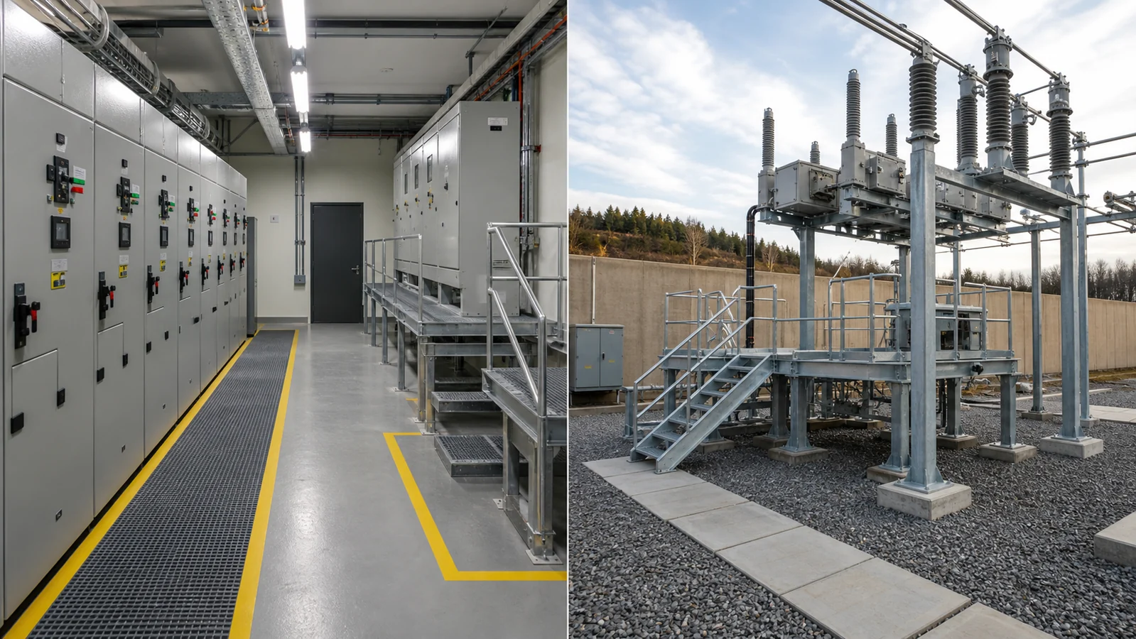
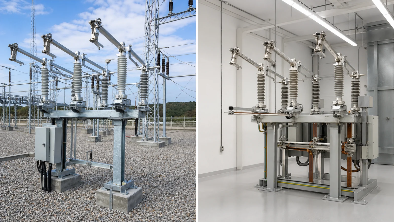
Indoor switchroom and outdoor substation yard showing the contrasting installation contexts that drive disconnect switch selection differences.
The table below contrasts the principal installation-context factors for indoor and outdoor disconnect switches. It is a diagnostic framework, not a specification — actual values and requirements must be confirmed for each project against the applicable authority documentation, such as the relevant IEC standard available from the IEC Webstore.
| Installation Factor | Indoor Context | Outdoor Context |
|---|---|---|
| Environmental exposure | Controlled ambient; contamination level typically lower | Direct weather: precipitation, UV, ice, wind, dust, and biological fouling |
| Enclosure requirement | Panel-integrated or open-type within switchboard or MCC | Weatherproof housing; sealing class is a project-specific input |
| Insulator selection | Pollution class matched to indoor environment | Pollution class per site survey; creepage distance project-specific |
| Operating mechanism reach | Flush or recessed handle on panel face; interlocks per layout | Extended rod, crank, or motorised actuator depending on mounting height and safe operating distance |
| Clearance requirements | Determined by voltage class and panel arrangement | Determined by voltage class, wind loading, and live-part separation to adjacent structures |
| Access pathway | Through building access control; key or padlock interlock | Through yard access control; may require elevated platform or insulated operating rod |
| Ambient temperature range | Narrower and more stable | Wider and site-dependent; altitude correction may apply |
| Auxiliary wiring | Short runs inside panel or cubicle | Longer conduit or cable routes; weather-sealed entry points required |
| Mounting base | Brackets to panel frame or wall | Concrete pad, steel structure, or pole mount; civil scope varies by project |
| Maintenance access | Defined by walkway and working-space rules inside building | Defined by yard layout, live-part clearances, and safe working distance |
Because both columns contain project-specific ranges rather than fixed values, copying a single entry from a previous installation without verifying site conditions introduces risk. Each project requires a fresh review of every factor.
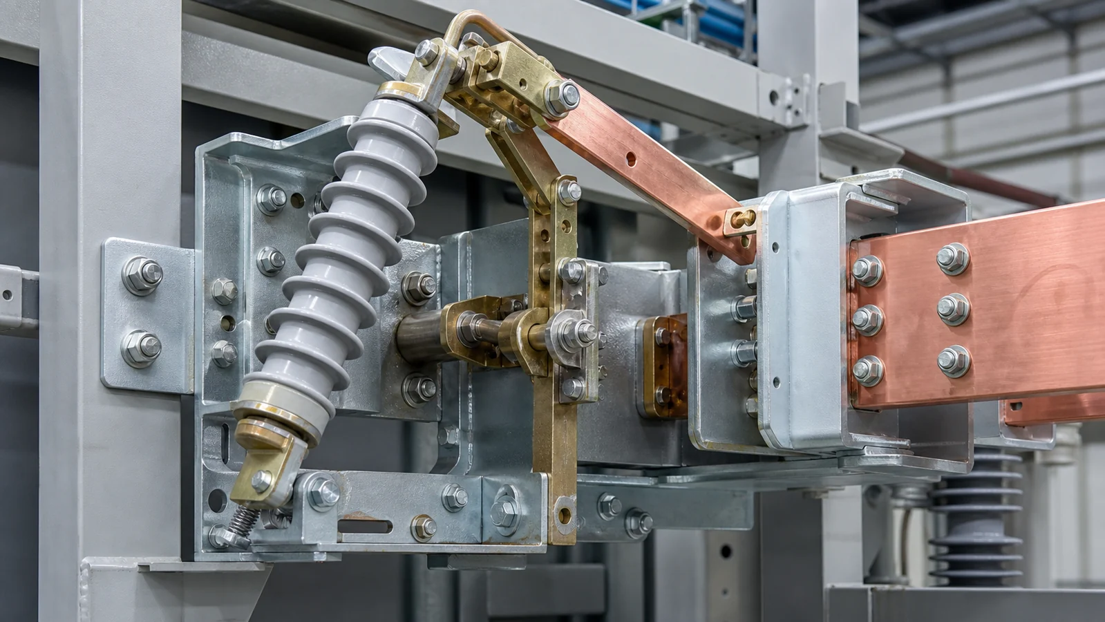
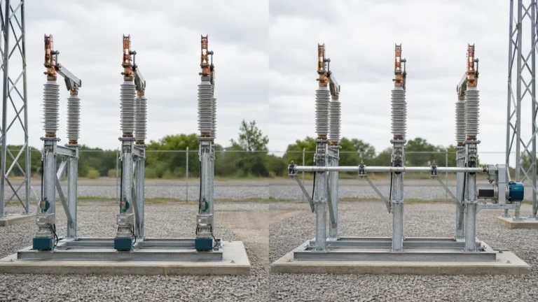
Mounting arrangement, operating mechanism reach, and connection interface details reviewed during project engineering for both indoor and outdoor disconnect switch installations.
Mounting. Indoor disconnect switches may be mounted to a panel frame, a wall bracket, or a cubicle structure. The orientation — vertical, horizontal, or angled — and conductor entry direction are determined by the panel layout drawing. Outdoor units require a foundation or mounting structure sized for equipment weight, short-circuit electromagnetic forces, wind loading, and, in applicable zones, ice and seismic events. Neither mounting hardware type nor foundation dimensions can be treated as universal; both are engineering outputs for each project.
Operating mechanism. The mechanism must allow the person performing the isolation to remain at a safe distance from live parts and to apply the required operating force without postural hazard. For indoor units at accessible heights, a front-mounted handle or lever is typical; interlock provisions depend on adjacent equipment. For outdoor units at elevated mounting heights, the mechanism may be an extended vertical rod, a cable-and-crank arrangement, or a motorised actuator with local or remote control. Motorised actuation adds control wiring, position feedback contacts, and potentially SCADA integration to the project scope.
Connection interface. The connection arrangement — busbar, lug, cable, or overhead line termination — is a project-specific input that affects terminal sizing, conductor entry direction, and the insulation geometry around the connection point. An outdoor overhead-line connection requires different terminal geometry and creepage path than an indoor busbar connection, even at the same voltage class.
Auxiliary interfaces. Auxiliary contacts for position indication, door interlock wiring, and heater or anti-condensation circuits are common on both indoor and outdoor units but differ in wiring method, cable entry, and sealing. Every auxiliary interface should be listed in the project specification so that the manufacturer and installer can confirm compatibility before order placement.
Access, safety, and inspection. The access arrangement must be compatible with the owner’s isolation and lockout/tagout procedure. Padlock provision, earthing-switch interlocking, and key-exchange schemes are all project decisions that must be confirmed before manufacture. Regular inspection intervals and inspection content — contact condition, insulator cleanliness, mechanism lubrication, sealing integrity — are defined by the owner’s maintenance philosophy and the manufacturer’s published guidance for the specific equipment.
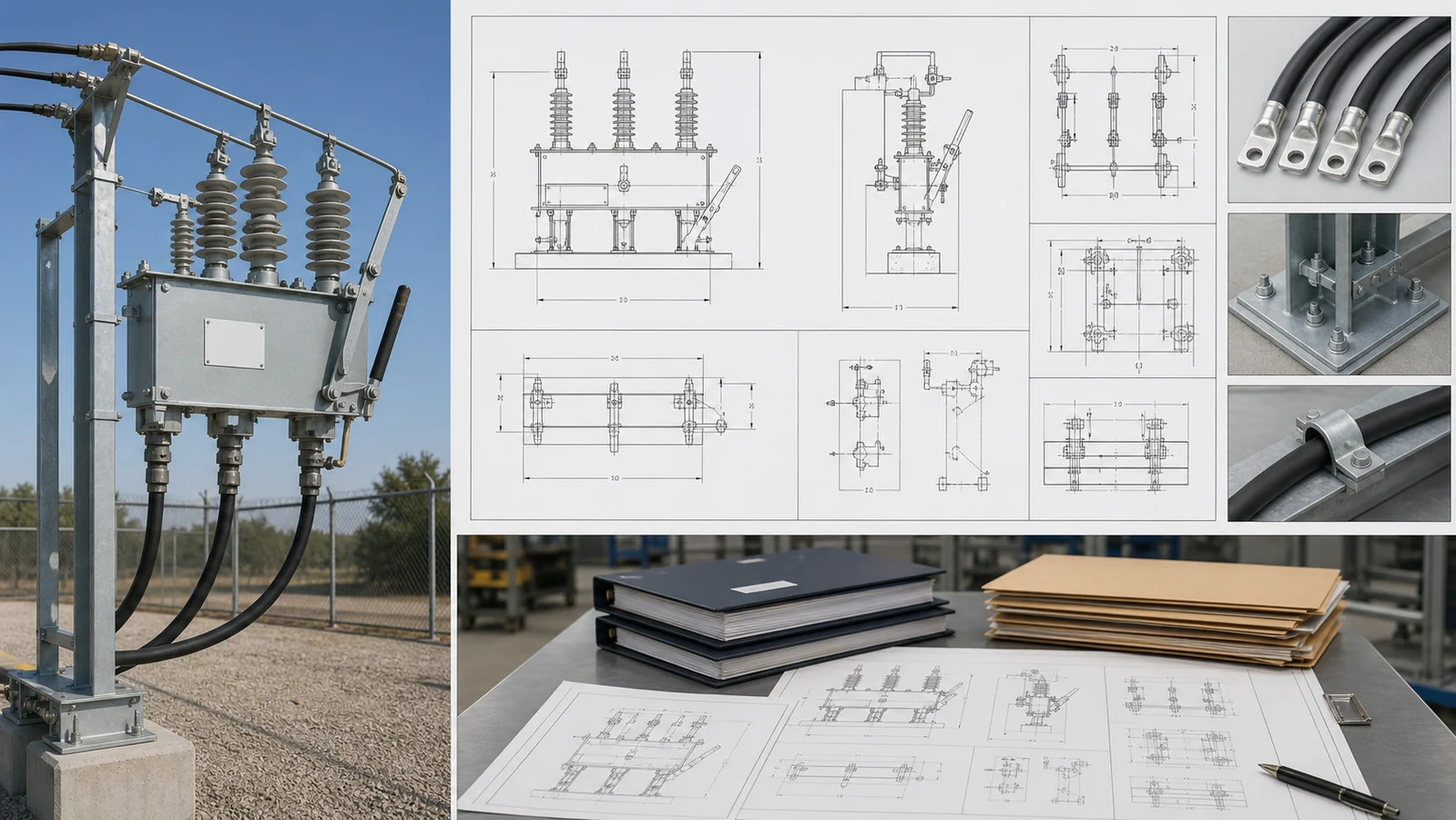
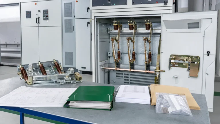
Project drawing and approval package for an installed disconnect switch, including general arrangement, single-line reference, nameplate data, and approval-stage markings.
Drawing, label, and approval workflow. The drawing package for a disconnect switch installation typically includes a general arrangement drawing, a nameplate data sheet, a single-line diagram reference, a wiring schematic for auxiliary circuits, and an installation instruction set. For outdoor equipment, civil interface drawings showing foundation bolt patterns and cable-entry coordinates are also required. Nameplate content is project-specific and must align with the applicable installation and safety-marking requirements for the jurisdiction. Labels for circuit identification, voltage class, and isolation-state indication are all project inputs. The approval workflow — whether the engineer of record, the utility, or a third-party inspector reviews drawings before release to manufacture — is determined by the owner and the regulatory framework, not by the equipment supplier alone.
Acceptance-source check. Before approving the equipment package, identify which document controls each review point. The project specification defines the required installation and duty inputs; the OEM manual and approved drawings define equipment-specific installation limits; and the applicable insulation, mechanism, and auxiliary-circuit data establish what can be confirmed. A test record, when required by the purchase specification, is an acceptance source for the stated inspection scope, not proof of a different site condition.
Submitting a complete request for quotation allows the equipment supplier to confirm feasibility, identify project-specific engineering requirements, and return a proposal that covers the actual scope. Incomplete RFQs produce proposals built on assumptions that may not match site conditions, leading to change orders and schedule risk.
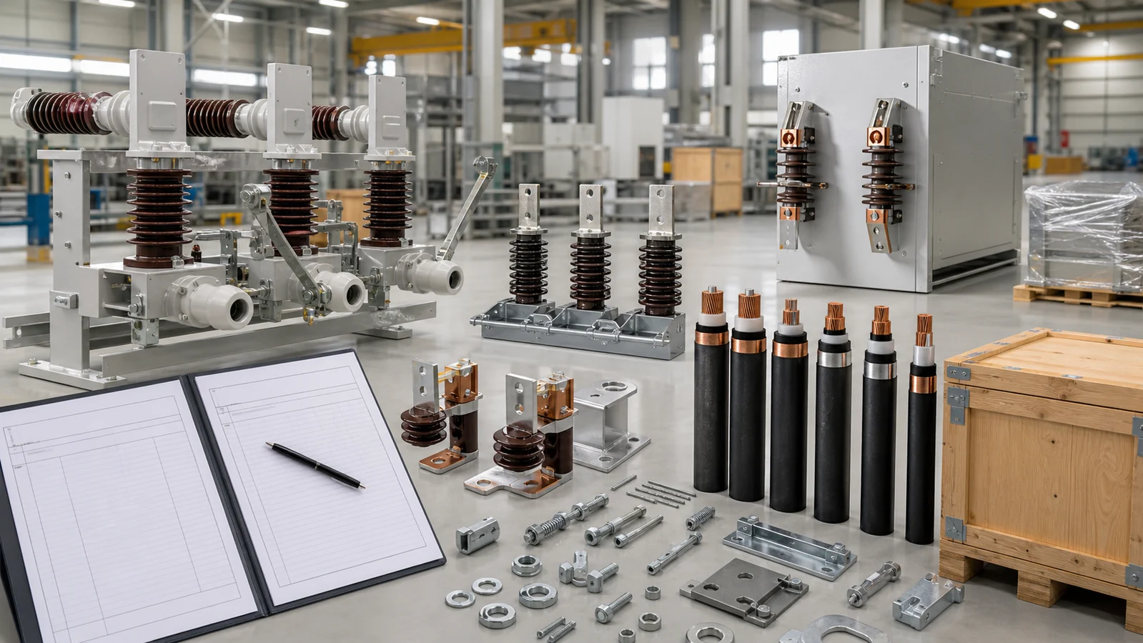
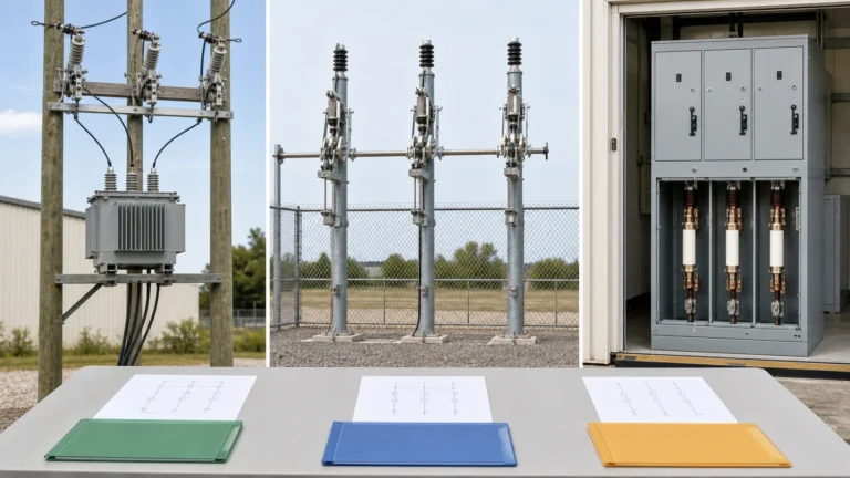
Buyer RFQ review showing equipment data, mounting and environmental inputs, and packing and logistics requirements as presented to the supplier.
Safe RFQ diagnosis: is the correct device class specified? Before requesting a disconnect switch quotation, confirm that the application genuinely requires only isolation — not load interruption or fault clearing.
| Condition at the Point of Isolation | Device Class to Specify |
|---|---|
| Circuit will always be de-energised before the switch is operated | Disconnect switch (isolation duty) |
| Circuit may be live and carrying load current when operated | Load break switch with rated load-interrupting duty |
| Overcurrent protection and isolation are both required at the same point | Fuse disconnect switch |
| Fault-interrupting duty is required | Circuit breaker or other fault-interrupting device — not a disconnect switch |
If the application falls outside the first row, a disconnect switch alone is not the correct solution regardless of its current rating.
Buyer input list. The following inputs should be stated explicitly in every RFQ submitted to XIYA POWER’s distribution switching equipment range:
Providing complete inputs at RFQ stage eliminates the most common cause of post-order scope changes.
A basic disconnect switch is an isolation device and should not be operated under load unless the equipment is specifically rated and approved for load-breaking duty. Operating a standard disconnect switch under load can cause sustained arcing, equipment damage, and serious hazard to personnel. Where load interruption is required at the point of isolation, specify a device with the correct load-breaking rating for the circuit conditions — not a basic disconnect switch.
The core isolation function is identical. The differences lie in the installed arrangement: outdoor equipment requires weatherproof sealing, insulators with a creepage distance matched to the site’s pollution class, operating mechanisms that allow safe operation from a safe working distance, and mounting structures sized for wind, ice, and other mechanical loads. Indoor equipment is designed for a controlled environment and is typically integrated into a panel or cubicle. Neither category has a single universal construction — both are configured to project-specific inputs.
No. Voltage class is one of many required inputs. Current rating, pollution severity, altitude, ambient temperature range, mounting arrangement, operating mechanism type, connection interface, and auxiliary requirements all affect the correct equipment configuration. Two installations at the same voltage class but different sites can require substantially different equipment, and treating voltage class as the sole selection input produces specifications that cannot be reliably quoted or manufactured.
Clearance requirements are determined by the applicable electrical installation standard for the jurisdiction and voltage class, the equipment’s own rated minimum clearances, and — for outdoor equipment — wind loading and proximity to adjacent live parts or structures. The engineer of record for the installation is responsible for confirming that clearances are met in the as-installed arrangement. The equipment supplier can provide the equipment’s rated clearance values; translating those into a compliant installed layout is a project engineering responsibility.
Auxiliary contacts provide position feedback signals used for local indication, interlocking with adjacent equipment, SCADA or control-system monitoring, or safety interlock schemes. The number of contacts required, their electrical rating, the control supply voltage, and the wiring method are project-specific inputs that must be stated in the specification. Auxiliary contacts are not always included as standard on every disconnect switch configuration; availability and specification should be confirmed at RFQ stage rather than assumed.