Quotation form
Send an inquiry
Start with the basics. Our team can follow up for missing drawings, standards or packing details.
Submitted details are used only for quotation, technical review and project communication.

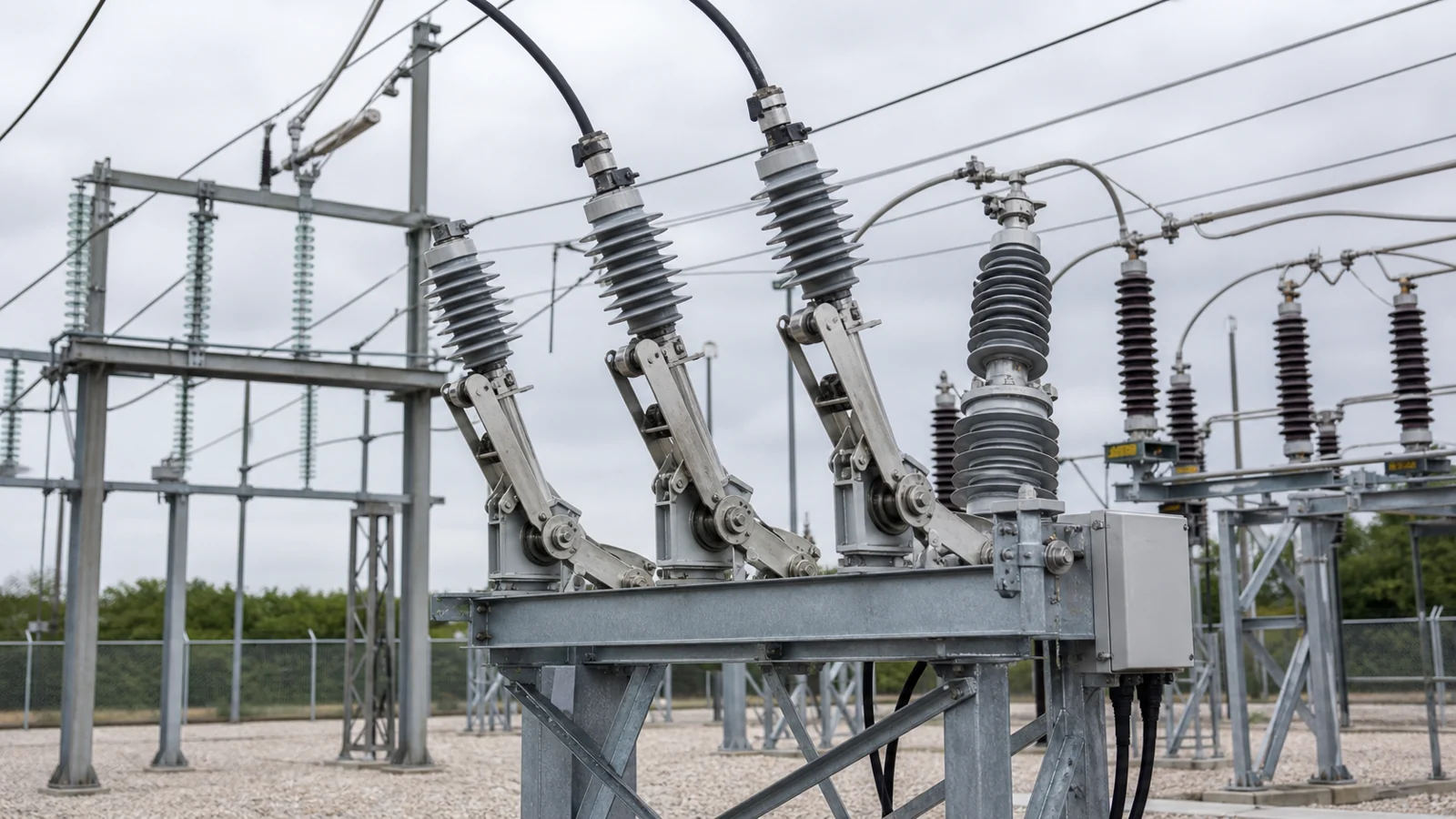
A load break switch (LBS) is a medium-voltage switching device rated to make and interrupt load current — the normal operating current of an energized circuit — at a voltage class confirmed in its approved equipment data. That single capability, load switching, is the device’s defining characteristic and its primary boundary. Understanding where that boundary sits — and where it does not extend — is the essential starting point for any engineer or buyer working with medium-voltage distribution equipment.
A load break switch allows an operator to open or close a live feeder carrying its rated load current. This makes sectionalizing, load transfer, and tie-point operation possible without first de-energizing the upstream source. In a medium-voltage distribution system, that capability reduces outage scope and enables controlled switching sequences.
Interruption boundary — confirm before specifying. A load break switch is not rated to interrupt fault current unless the project specification and the OEM’s approved equipment data explicitly state that duty. IEC 62271-103 defines duty classes for medium-voltage switches; do not assume short-circuit breaking unless the specific equipment has a confirmed rated capability. Engineers and operators must verify each interruption duty against approved equipment data and the project protection scheme before a device is selected or operated.
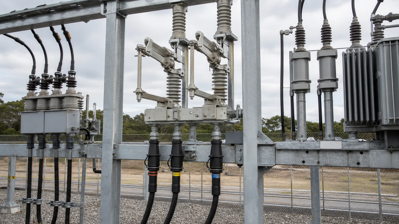
FIG-01: Illustrative medium-voltage feeder arrangement showing the load break switch position between the source bus and downstream feeder protection — position and ratings are project-specific and must be confirmed against approved single-line drawings.
Selecting the correct switching device requires matching required duties to confirmed device capabilities. The four device types most commonly encountered in medium-voltage distribution serve overlapping but distinct roles.
| Device | Rated load switching | Rated isolation | Rated fault interruption | Inherent protection role |
|---|---|---|---|---|
| Isolation / disconnect switch | No — must not operate under load | Yes — provides visible open gap | No | None; follows upstream protection |
| Fuse disconnect switch | Depends on design and rating — confirm per approved data | Often yes | Fuse element only, within its I²t limit | Overcurrent via fuse; switching duty varies by model |
| Load break switch | Yes — rated load current at rated voltage | Yes — isolation in open position per approved data | No (unless specifically rated and certified) | None inherently; coordinates with upstream or downstream protection |
| Circuit breaker | Yes | Typically no visible gap without racking | Yes — rated short-circuit breaking current | Overcurrent and fault protection per relay settings |
Isolation-only disconnect switches provide the safe working gap required before maintenance. Because they are not designed to interrupt arc energy, opening them under load risks severe arc flash and equipment damage. The switching sequence must confirm that all upstream protection has been opened and verified before an isolation-only switch is operated. XIYA POWER’s disconnect switches product line covers isolation-duty applications.
Fuse disconnect switches add an overcurrent interruption element to the isolation function. The fuse element responds to sustained overcurrents and certain fault levels within its published current-limiting range; the switch body itself may or may not be rated for load switching depending on the specific model and its approved data. Engineers must not assume load-switching capability without confirming it in OEM documentation. XIYA POWER’s fuse disconnect switches page provides product-specific details.
Circuit breakers are rated to make and break fault currents up to their rated short-circuit breaking current, and their protection relay interface enables automatic tripping. They are the appropriate device where automatic fault clearing is required. See XIYA POWER’s circuit breakers range for applicable ratings.
Load break switches occupy a specific niche: manual or motorized load current switching combined with isolation, without inherent fault-clearing capability. They are appropriate where load transfer, sectionalizing, or normally open tie functions are required and where upstream or downstream protection devices handle fault clearing independently. Confirming that the upstream relay and breaker will clear faults within the LBS’s rated short-time withstand duration is a required project engineering step — not a default assumption.
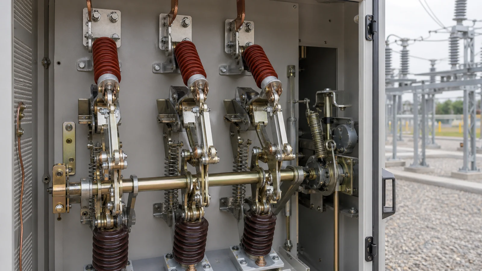
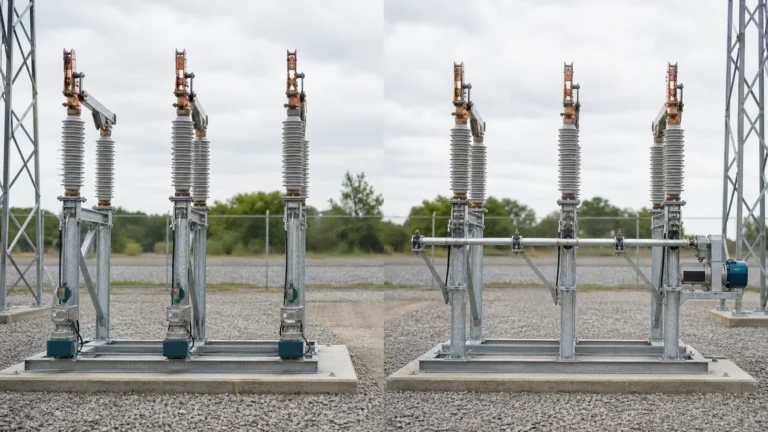
FIG-02: Illustrative cross-section of a load break switch showing the insulated interrupter chamber and mechanism linkage — actual construction details vary by manufacturer design and voltage class; refer to the OEM manual for the specific equipment.
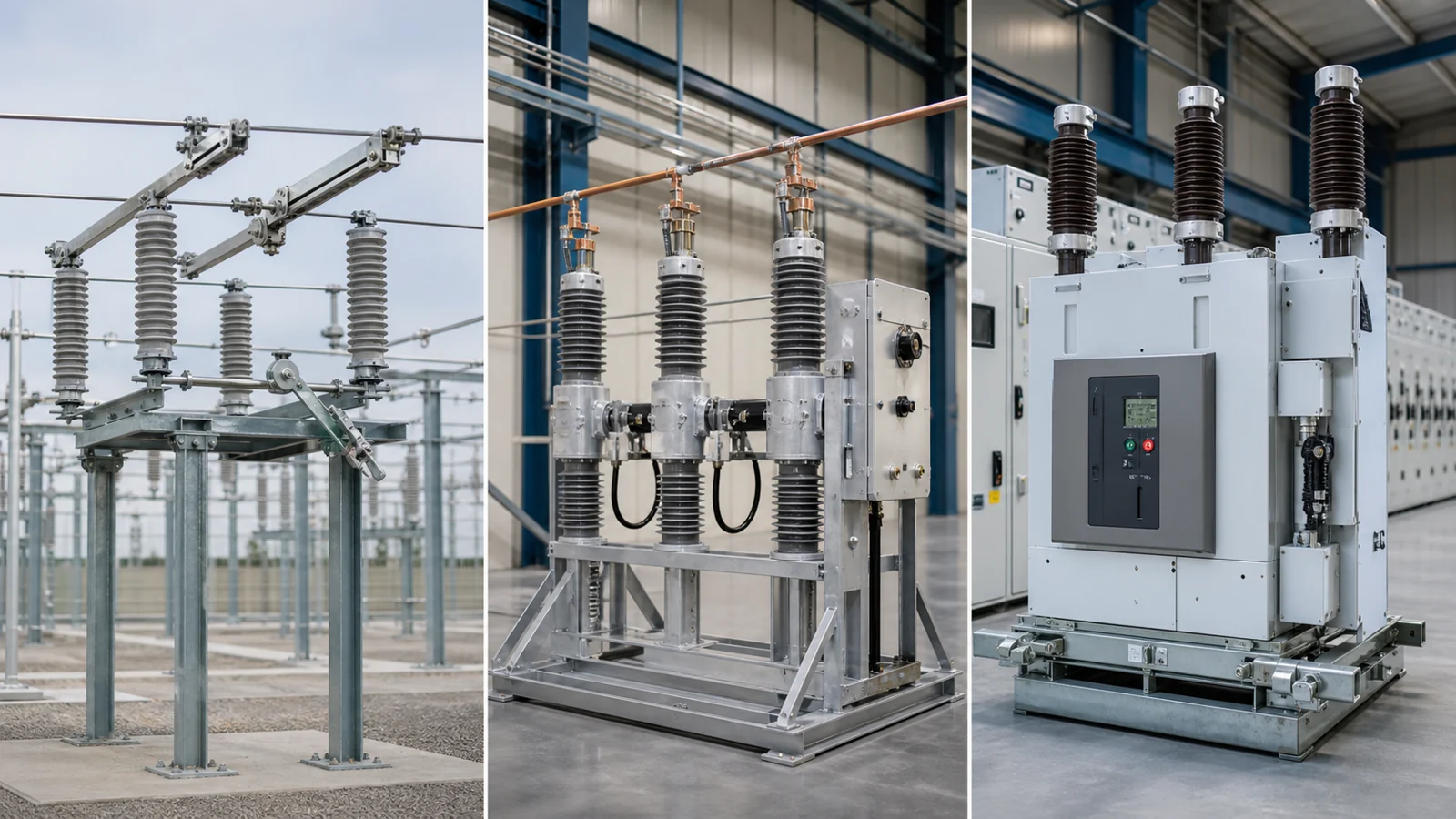
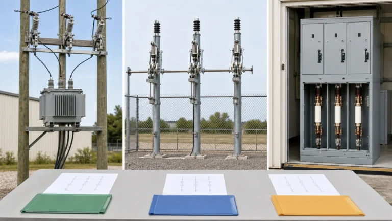
FIG-03: Illustrative comparison of device contexts — isolation duty, load switching duty, and fault-interruption duty — showing that each requires a different confirmed device capability rather than a universal switching function.
Every load break switch application involves project-specific inputs that cannot be generalized across sites. The following categories represent the minimum confirmed data a project team should assemble before specifying or installing a load break switch.
The rated maximum voltage, rated normal current, rated short-time withstand current, and rated peak withstand current must all be confirmed from the OEM’s approved equipment data and cross-checked against the project single-line diagram and system fault level study. Using an LBS rated below the available fault level — even for the brief interval before upstream protection operates — creates a risk of equipment failure during a fault event.
Load break switches may be manually operated, spring-charged for local operation, or motor-operated for remote control. Where remote switching is required, the control voltage, communication protocol, and interlock wiring must match the SCADA or protection system design. Motor-operated mechanisms require confirmed control power availability and, in many applications, anti-pumping and position-confirmation logic defined in the approved wiring schedule.
Ambient temperature range, altitude, humidity class, and pollution severity — as defined in the project specification — determine whether the standard enclosure is adequate or whether special coatings, heaters, or sealed gas-insulated construction are required. Altitude correction factors apply to insulation levels above 1,000 m and must be confirmed against the approved insulation coordination study.
A load break switch does not trip automatically on fault current. The protection scheme — typically an upstream circuit breaker with overcurrent relays — must be confirmed to clear fault current within the LBS’s rated short-time withstand duration. If the scheme includes downstream fuses, the fuse-to-LBS coordination must be verified: the fuse must clear before the LBS’s thermal and mechanical limits are exceeded. Documenting this coordination in a protection settings schedule and relay coordination study is a project engineering requirement.
Mechanical and electrical interlocks prevent incorrect operation sequences. Common interlocks include: preventing LBS closure onto a faulted feeder where earthing switches or protection blocking contacts are used; preventing disconnection of cable or busbar while the LBS is closed; and ensuring earthing switches cannot be closed while the LBS remains connected to a live source. The required interlock logic is project-specific and must be detailed in the approved interlocking schedule.
Acceptance of a load break switch installation draws on exactly four document sources: the project specification, which defines the rated duties and interlock requirements the equipment must satisfy; the OEM manual, which defines installation clearances, tightening torques, mechanism adjustment, and operational limits; the insulation test data, which confirms that power-frequency and impulse withstand levels meet the approved insulation coordination study after installation; and the factory and site test record, which provides documented evidence of routine and type tests completed before and after installation. No other source substitutes for these four when approving the equipment for energization.
The following table is explicitly illustrative and does not represent any specific site, event, measurement, or test result. It is provided to help engineering and procurement teams frame initial questions before engaging with a supplier or service technician.
| Symptom | First test | Likely cause | Next action |
|---|---|---|---|
| Switch fails to open under load; handle does not complete travel | Check mechanism spring charge indicator and linkage alignment | Spring not charged, cam worn, or mechanism binding | Consult OEM manual; do not force mechanism; isolate upstream before inspection |
| Visible burn marks or deposit at interrupter contacts | Inspect contact wear indicator against OEM wear limits in the manual | Contact erosion beyond rated interruption cycles | Replace interrupter insert per OEM procedure; review operating cycle log |
| Insulation resistance below project specification at routine test | Perform power-frequency withstand test per project test record procedure | Surface contamination, moisture ingress, or tracking damage | Clean and dry per OEM instructions; repeat insulation test; escalate if failure recurs |
| Motor-operated mechanism does not respond to remote close command | Check control voltage at mechanism terminal; verify position feedback relay state | Control power loss, wiring fault, or anti-pumping lockout active | Restore control power or clear lockout per approved interlock schedule before re-commanding |
When requesting a quotation for a medium-voltage load break switch, provide the following project-specific data. XIYA POWER’s load break switches product line can be specified using this input structure.
| RFQ input field | Example format | Notes |
|---|---|---|
| Rated voltage (kV) | 12 / 24 / 36 kV | Confirm from insulation coordination study |
| Rated normal current (A) | 630 A / 1250 A | Confirm from load flow study; include growth allowance |
| Rated short-time withstand current (kA, duration) | 16 kA / 1 s | Must equal or exceed available fault level at installation point |
| Rated peak withstand current (kA) | 40 kA peak | Derived from fault level study; verify against OEM data sheet |
| Operating mechanism type | Manual / spring / motor-operated | Confirm SCADA integration requirement |
| Control voltage | 24 V DC / 110 V DC / 230 V AC | Match to available station battery or UPS supply |
| Enclosure type and IP class | Indoor / outdoor; IP54 | Per project environmental specification |
| Number of poles | 3-pole / single-pole | Confirm from network configuration |
| Earthing switch required | Yes / No; rated make current (kA) | Per project earthing and safety requirements |
| Applicable standard | IEC 62271-103 | Confirm edition and any national deviation per project spec |
| Required documentation | Type test reports, routine test certificates, OEM manual, drawings | Specify format (PDF, DWG) and delivery language |
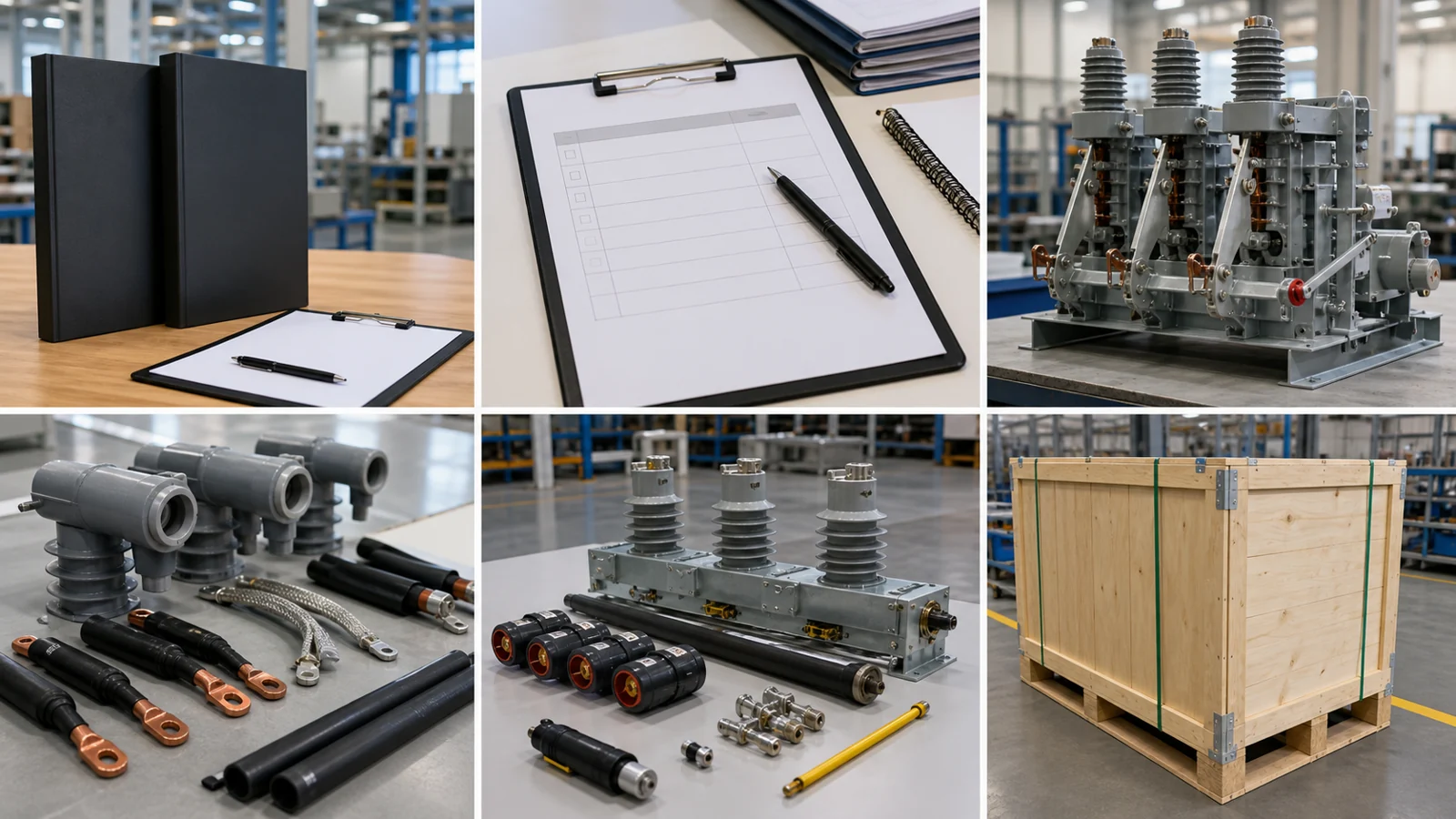
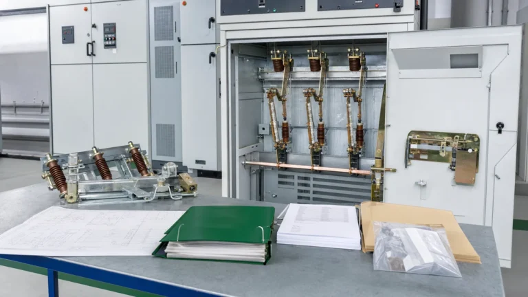
FIG-04: Illustrative buyer RFQ and approval package checklist for a medium-voltage load break switch, showing the document types required from specification through commissioning — actual document list is project-specific.
Not unless the specific equipment’s approved data and type test certificates explicitly confirm a rated short-circuit breaking capability. Standard load break switches are rated for load current interruption only. Fault interruption is the duty of an upstream or downstream circuit breaker or current-limiting fuse, coordinated with the LBS’s short-time withstand rating. The protection scheme must be confirmed against approved equipment data before any fault-clearing assumption is made.
An isolation switch — also referred to as a disconnect switch — is rated to provide a safe, visible open gap for maintenance isolation, but it must never be operated while current is flowing in the circuit. A load break switch is rated to open and close the circuit under normal load current. Using an isolation-only switch under load risks violent arcing and equipment damage. This distinction must be confirmed from the device nameplate and approved equipment data, not inferred from physical appearance alone.
Where a fuse protects the downstream feeder, the fuse must clear fault current within the load break switch’s rated short-time withstand duration so that the LBS is not exposed to fault current beyond its thermal and mechanical limits. This coordination is verified in a time-current coordination study that plots both the fuse melting characteristic and the LBS withstand limit on the same axes. The result must be documented in the approved protection coordination study before the installation is accepted.
The minimum document set consists of four sources: the approved project specification confirming required rated duties and interlock requirements; the OEM manual confirming installation requirements and operational limits; the insulation test data confirming withstand levels after installation; and the factory and site test record confirming that required routine and type tests have been completed and signed off. No verbal confirmation or inference substitutes for these documents when approving energization.
No. A motor-operated load break switch receives a remote open or close command and executes a single switching operation under load current. An automatic recloser is a circuit breaker-class device that detects a fault, trips, and then executes a programmed re-closing sequence to restore supply after a transient fault — functions that require rated short-circuit breaking capability. A motor-operated LBS can participate in a SCADA-controlled sectionalizing scheme, but it does not provide fault detection, automatic tripping, or reclosing functions unless paired with separate protection devices and confirmed in the project design.
All ratings, application guidance, interlock descriptions, and document requirements in this article are general educational context only. Confirm all values and requirements against the project specification, approved equipment data, OEM manual, and applicable standards before specifying, installing, or operating any switching device.