Quotation form
Send an inquiry
Start with the basics. Our team can follow up for missing drawings, standards or packing details.
Submitted details are used only for quotation, technical review and project communication.

A surge arrester is a voltage-clamping device installed on a distribution system to limit the peak transient overvoltage that reaches connected equipment. When a lightning stroke terminates on or near a distribution line, or when a switching operation collapses stored inductive energy, the resulting surge travels along the conductor. Without a diversion path, the transient voltage across insulation can exceed the equipment’s withstand rating and cause immediate or cumulative dielectric damage.
A surge arrester addresses that specific threat. It provides a low-impedance path to earth for the impulse current while recovering its full insulating capability once the voltage returns to the normal power-frequency range. This action limits the overvoltage exposure of the protected equipment to a level that corresponds to the arrester’s protective characteristic.
Two boundaries are equally important. First, a surge arrester is not the overcurrent protective device that clears a system fault, and it cannot replace a circuit breaker or a drop-out fuse in the protective scheme. Second, no arrester guarantees that the protected equipment will survive every transient event. The degree of protection depends on the coordination between the arrester’s characteristics and the insulation level of the protected device, the conductor run between arrester and equipment terminal, the earthing arrangement, and the incoming surge — all project-specific inputs evaluated against approved data.
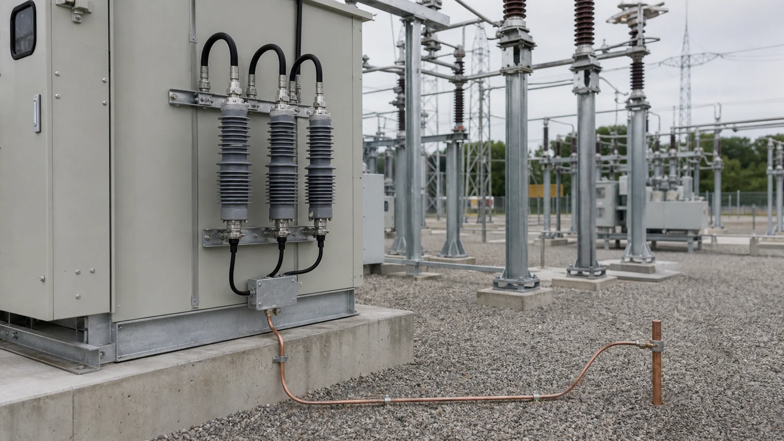
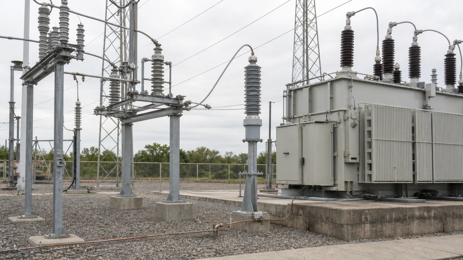
FIG-01: Typical surge arrester position in a distribution circuit, shown adjacent to the protected distribution equipment to minimize the separation distance between arrester terminal and equipment insulation.
Modern distribution surge arresters are built around metal-oxide varistor (MOV) disc columns. The MOV material — primarily zinc oxide with small additions of other metal oxides — exhibits a sharply nonlinear voltage-current relationship. At normal power-frequency voltage, the column presents very high impedance and draws only a small leakage current. When a transient drives the terminal voltage above the arrester’s reference level, the impedance drops dramatically and the column conducts the impulse current to the earthing connection. When the voltage falls back to normal, the MOV self-restores to its high-impedance state without requiring mechanical intervention.
The column is housed in a porcelain or polymeric insulator body that provides the required external creepage distance and seals the active elements from moisture. Polymeric housings are increasingly common in distribution applications because they resist vandalism, weigh less, and are less prone to shattering under mechanical stress.
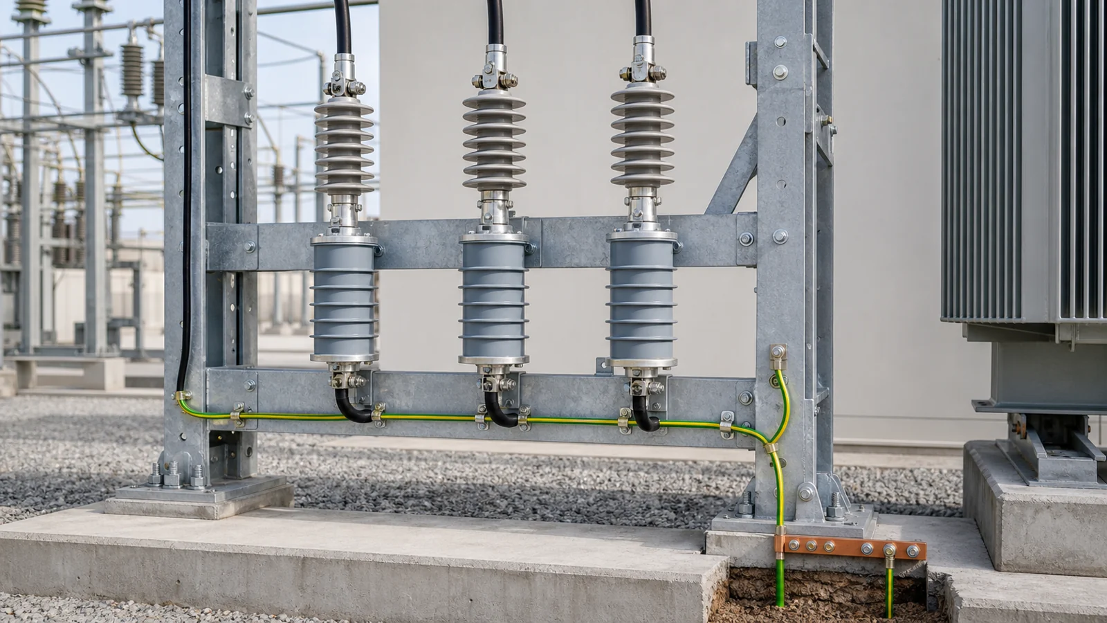
FIG-02: Conceptual cross-section showing the MOV column and the earthing-path route from the line terminal through the active element to the earth conductor — specific labels, dimensions, and ratings depend on the approved product data sheet.
The performance of a surge arrester depends heavily on the earthing path. Impulse current diverted through the MOV column must return to the remote earth through the earth conductor, the earthing electrode, and the soil. Any impedance in that path — conductor inductance, connection resistance, or inadequate electrode contact with soil — adds to the residual voltage seen at the equipment terminal. Earthing conductor selection, electrode design, and verification of earth resistance are all project-specific requirements that must follow the project specification, the OEM installation manual, and the relevant national or utility earthing standards. No universal earth resistance value is stated here because the acceptable limit is determined by the arrester’s protective characteristics and the equipment insulation level, both of which vary by application.
A surge arrester occupies a distinct and complementary role in the distribution protective scheme. The table below summarizes how it differs from the other principal devices in a coordinated system.
| Device | Primary threat addressed | Operating mechanism | Post-operation state | Carries load current? |
|---|---|---|---|---|
| Surge arrester | Transient overvoltage (lightning, switching) | Voltage-dependent impedance (MOV clamp) | Self-restores; no manual reset | No — leakage only at normal voltage |
| Circuit breaker | Overcurrent, short circuit, system switching | Mechanical contact separation | Requires manual or automatic reclose | Yes |
| Drop-out fuse | Overcurrent, short circuit | Fusible element melts, tube drops | Requires manual replacement | Yes |
| Insulator / bushing | Dielectric stress at power frequency | Passive insulation | Permanent unless damaged | No |
A coordinated protection scheme uses all of these devices together. Removing or substituting any one for another leaves a gap that the remaining devices are not designed to fill.
The physical separation between a surge arrester’s earth terminal and the insulation of the protected equipment directly influences the voltage that appears across that insulation during a surge event. A shorter lead length reduces the inductive voltage addition during the fast-front current impulse. For this reason, arresters are typically installed as close as practicable to the protected terminal — at the transformer primary bushing, at the cable termination, or at the entry point of an overhead line into a distribution substation.
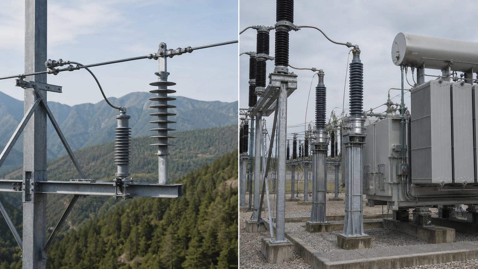
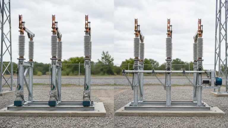
FIG-03: Comparison of line-mounted and station-mounted arrester installations — the station-mounted position minimizes distance to the protected equipment terminals, while the line-mounted position provides primary protection to the line and distant-end equipment.
Line-mounted arresters serve a different coordination function from station-mounted units: they reduce the surge that arrives at the substation by absorbing energy closer to the lightning attachment point before it builds up along the line. Project engineers select the combination of line and station arresters based on a coordination study that accounts for line length, span geometry, and the insulation levels of all equipment in the protected section. That study is outside the scope of a general product description and must be performed for each project.
A surge arrester and a fuse or circuit breaker on the same feeder must be coordinated so that a surge event does not cause the overcurrent device to operate unnecessarily. Because the arrester diverts impulse current to earth, the overcurrent device sees only the power-frequency follow current after the surge, if any. An adequately rated arrester will suppress or limit that follow current so that the overcurrent device does not interrupt. Coordination margins are confirmed by the arrester’s rated voltage, continuous operating voltage, and energy absorption capability relative to the system fault level — all values that come from the approved product data sheet and the project specification.
You can explore the full range of distribution switching equipment from XIYA POWER to identify the components that belong in a coordinated scheme alongside surge arresters.
Correct installation requires that the line-terminal connection be made with a short, straight conductor of the cross-section specified in the OEM manual, that the earth conductor follow the shortest practical path to the earthing point, that the mounting hardware be tightened to the specified torque, and that any sealing points on the housing be inspected for integrity before energization. The OEM installation manual is the authoritative source for all mechanical and electrical connection requirements.
In-service surge arresters should be periodically inspected for visible contamination, cracking, or tracking on the housing surface; corrosion at the earth-terminal connection; and displacement of the mounting bracket. Some designs incorporate a surge counter or a leakage-current monitor at the earth terminal. Where these are fitted, the recorded data — number of operations and leakage current trend — should be reviewed at each inspection interval defined in the project maintenance plan. Changes in leakage current over time may indicate moisture ingress or partial degradation of the MOV column and should prompt further investigation per the OEM manual.
Acceptance of a surge arrester installation should be based solely on the project specification (which defines the rated voltage class, system earthing arrangement, and required protection level), the OEM installation and operating manual (which defines torque values, conductor specifications, and test procedures), the insulation data for the protected equipment (which establishes the coordination target), and the test record produced during commissioning (which verifies continuity of the earthing path, absence of visible damage, and any on-site verification tests required by the specification). No other source constitutes an acceptance basis.
Applicable arrester standards and the edition required for a project should be confirmed through the IEC Webstore, together with the approved product and project documentation.
The table below is explicitly illustrative. It describes symptom patterns that may prompt investigation of surge arrester condition. Actual diagnosis requires measurement, comparison against the OEM baseline, and interpretation by a qualified engineer. No fault finding, rating, or outcome should be inferred from this table without site-specific data.
| Symptom | First test | Likely cause | Next action |
|---|---|---|---|
| Visible cracking or carbonized tracking on housing | Visual inspection of full housing surface | Sustained contamination flashover or mechanical impact | Remove from service; consult OEM replacement criteria |
| Elevated or trending leakage current at monitor | Compare reading against OEM baseline and trend history | MOV column aging, moisture ingress, or surface contamination layer | Schedule detailed diagnostic; refer to OEM manual |
| Surge counter showing unusually high operation count | Review count against expected activity and log dates | Repeated surge events indicating inadequate shielding or earthing | Commission earthing survey; evaluate lightning exposure |
| Corrosion at earth-terminal clamp or conductor | Inspect clamp and conductor; check contact condition | Inadequate sealing, galvanic incompatibility, or exposed conductor | Re-terminate with correct hardware; re-verify earthing path |
| Physical displacement or tilted mounting | Inspect mounting bracket and hardware torque | Wind load, vibration, or installation error | Re-install to OEM torque specification; inspect housing for stress damage |
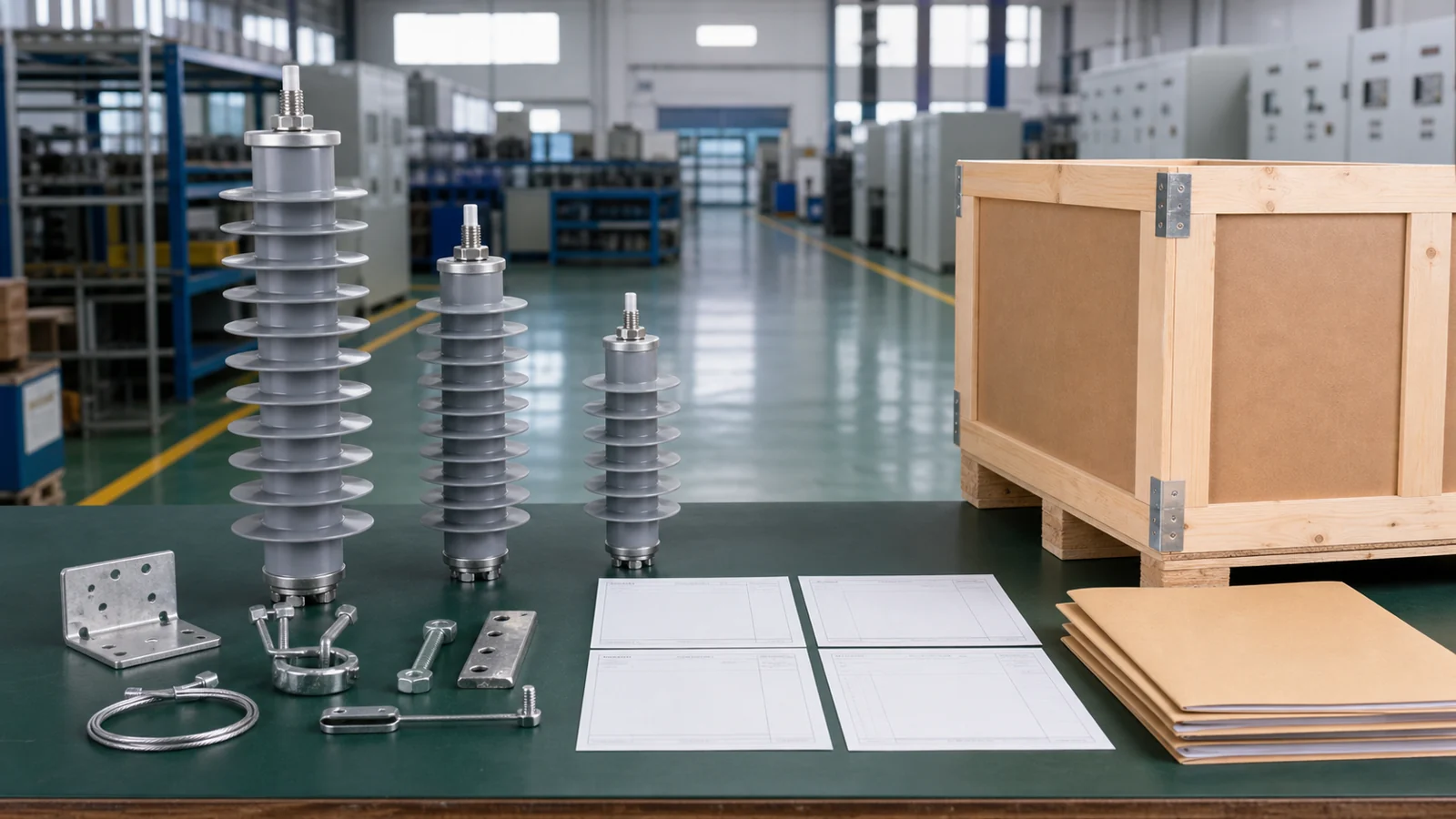
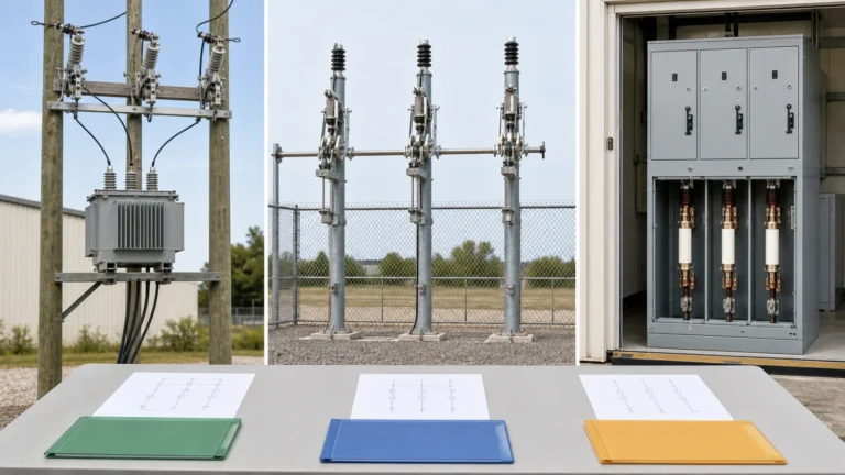
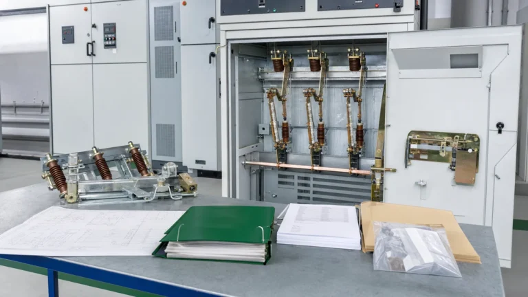
FIG-04: Illustrated document and data package that a buyer should assemble before issuing an RFQ for surge arresters — combining system parameters, protected-equipment insulation data, earthing design, and applicable standards.
When preparing a request for quotation, providing complete system data allows the supplier to propose an arrester class and model coordinated with the protected equipment. The following inputs are typically required.
| RFQ Input | Why it is needed | Where to find it |
|---|---|---|
| System nominal voltage (kV) and earthing arrangement | Determines rated voltage and continuous operating voltage class | Network data sheet or single-line diagram |
| Maximum continuous operating voltage at installation point | Ensures arrester is not stressed by normal voltage variations | Utility voltage-regulation documentation |
| Lightning overvoltage exposure (line or cable entry) | Guides line vs. station class selection | Insulation coordination study or project specification |
| Basic impulse insulation level (BIL) of protected equipment | Defines the coordination target the arrester must meet | Protected-equipment nameplate or type-test certificate |
| Prospective fault current at installation point | Determines required disconnector or fault-withstand capability | Short-circuit study |
| Earthing arrangement (solid, resistance, resonant, TT, TN, IT) | Affects TOV withstand and rated voltage selection | Project earthing design drawing |
| Environmental conditions (pollution severity, altitude, UV exposure) | Affects housing creepage class and material selection | Site environmental survey |
| Mounting configuration (pole-top, substation structure, cable box) | Determines housing design and mounting hardware | Site layout drawing |
| Required standards (IEC edition, ANSI, utility specification) | Ensures compliance with project and grid-code requirements | Project specification |
In distribution engineering, “surge arrester” refers to a device installed on medium- or high-voltage systems to limit transient overvoltage at the network level, using an MOV column rated for the system voltage class. “Surge protector” typically refers to low-voltage plug-in or panel devices used at the equipment level inside buildings. The two devices operate on similar MOV principles but differ in voltage class, energy capability, mounting method, and the standards governing their testing and rating. They address different points in the supply chain and are not interchangeable.
No. A surge arrester limits transient overvoltage; it does not interrupt sustained overcurrent or fault current. A fuse or circuit breaker is required for those functions. Removing overcurrent protection from a feeder that has only a surge arrester leaves the line and connected equipment exposed to fault damage that the arrester is not designed to address. All three device types serve defined, complementary roles in a coordinated protection scheme and must be applied together.
The shorter the total lead length from the line terminal through the arrester and earth conductor to the protected equipment terminal, the lower the inductive voltage addition during a fast-front surge. Project engineers specify the maximum acceptable separation distance based on the insulation coordination study for the specific installation. As a general principle, the arrester should be mounted as close to the protected terminal as the physical layout permits, and the earth conductor should take the shortest, most direct path to the earthing point.
A properly functioning MOV arrester self-restores to its high-impedance state once the transient passes and the voltage returns to the power-frequency operating range. Unlike a fuse, it does not require replacement after a single operation. However, very energetic events or repeated surges can cause cumulative degradation of the MOV material. Monitoring leakage current trend and surge counter readings at the intervals defined in the project maintenance plan provides early indication of column condition and should be standard practice wherever monitoring hardware is fitted.
At minimum, request the product data sheet confirming rated voltage, continuous operating voltage, protective characteristics, and housing class; the test report issued under the applicable edition of IEC 60099-4 or the project-specified standard; the installation and operating manual; and the declaration of conformity for the claimed standard. On project-specific orders, also request type-test certificates and, where required by the specification, routine test records for the delivered batch. These documents form the basis for acceptance review and should be retained with the project documentation throughout the asset’s operational life.