Quotation form
Send an inquiry
Start with the basics. Our team can follow up for missing drawings, standards or packing details.
Submitted details are used only for quotation, technical review and project communication.

A nameplate on a medium-voltage switchgear assembly is a statement of what the equipment is designed and tested to withstand under standardized conditions. It is not a certificate that the assembly is correct for a particular site, a substitute for a power-system study, or a confirmation that protection devices have been set or coordinated. Understanding that boundary is the starting point for every engineer, procurement officer, or facility manager who opens a switchgear submittal.
This article explains the principal rating families found on medium-voltage switchgear — rated voltage, insulation level, rated normal current, short-circuit withstand and interruption capability, and protection interface — and clarifies what each term means and, just as importantly, what it does not resolve on its own.
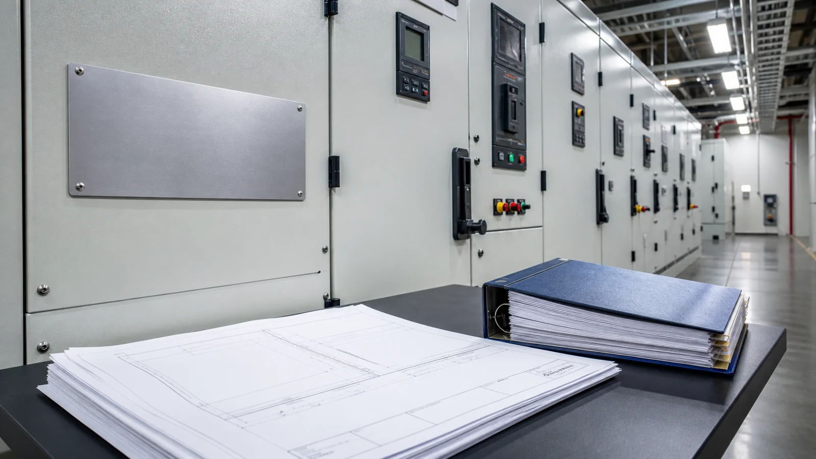
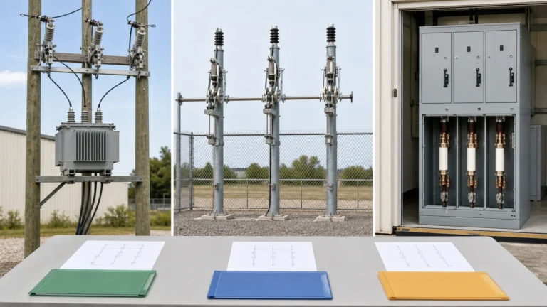
Figure 01: Relationship between a switchgear rating label and the system-document review context; the label defines equipment capability, while load-flow, short-circuit, and protection studies define site requirements that must be compared independently.
Rated voltage — sometimes written as rated maximum voltage — is the highest system voltage, phase-to-phase, for which the switchgear is designed. The applicable standard edition should be confirmed through the IEC Webstore and the approved project documentation. Selecting a class is not the same as confirming that the switchgear suits a particular bus voltage; nominal voltage, expected voltage rise, transformer tap position, and harmonic or transient conditions must be assessed against actual site data.
A cabinet bearing a given rated voltage confirms the manufacturer tested it at that class. Whether the local utility nominal voltage and its permitted tolerance band fall safely within that class is a site-engineering determination, not a label read.
Insulation level is expressed as two companion values: power-frequency withstand voltage and lightning impulse withstand voltage (also called the basic impulse insulation level, or BIL). Together they define the dielectric envelope the equipment has been proven to withstand under standardized test conditions.
Insulation level is not interchangeable with rated voltage. A system with a long overhead-line approach may require a higher impulse level than a purely cable-fed urban substation at nominally the same voltage class. The appropriate insulation level must be matched to the specific overvoltage environment, surge-protection scheme, and cable-termination design of the installation — none of which appear on the equipment nameplate alone.
Rated normal current is the continuous current the main bus and switching devices are designed to carry at a stated ambient temperature and with specified ventilation conditions. It does not represent the maximum load current the installation will actually draw; that figure comes from a load study incorporating demand factors, future growth projections, motor-starting transients, and any derating required for the actual enclosure temperature.
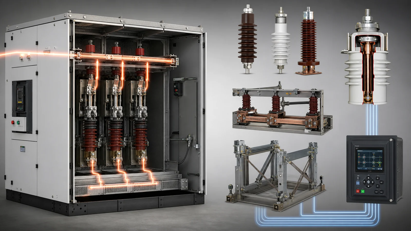
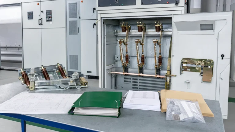
Figure 02: Conceptual arrangement of the four principal rating families — voltage, current, short-circuit, and protection interface — showing their independence and the separate site-study layer that links each to project requirements.
Specifying switchgear with a rated normal current that exceeds the calculated maximum demand is necessary, but the margin is a project-engineering decision, not a value readable from the label itself.
Short-circuit ratings divide into two related but distinct values.
Rated short-circuit withstand current (also written as rated short-time withstand current) is the peak and r.m.s. symmetrical current the bus system, enclosure, and all current-carrying parts are designed to carry for a specified duration without damage. It confirms mechanical and thermal integrity under fault conditions.
Rated short-circuit breaking current (for circuit breakers) or rated short-circuit making current (for switches and contactors) describes the interruption or closing capability of the switching device itself. These are not the same as the withstand rating of the bus assembly, and neither equals the actual fault current available at a particular point in the distribution network.
Determining actual available fault current requires a short-circuit study using the utility’s declared fault level at the point of supply, cable impedances, transformer impedances, and motor contributions. That study is performed by the engineer of record, not read from a nameplate. The cabinet rating must exceed the study result with the margin required by the project specification and applicable code; the comparison is a project task, not a label task.
The KYN28 metal-clad switchgear is an example of a withdrawable metal-clad design whose short-circuit parameters follow this same framework — labels document tested capability; site fault levels are determined by study.
Closely linked to withstand current is the rated duration: the number of seconds the equipment can sustain the rated fault current without inadmissible temperature rise. Relay operating time plus breaker opening time must sum to less than this duration under worst-case conditions. Verifying that relationship is a protection coordination exercise, not a label check.
Medium-voltage switchgear provides a physical and electrical interface for protective relays, current transformers (CTs), voltage transformers (VTs), and associated control wiring. Reading a switchgear rating label does not disclose protection settings, relay types, CT ratios actually required, or the coordination curves that govern relay pickup and time-delay selection. Those are determined through a dedicated protection study carried out against the specific network.
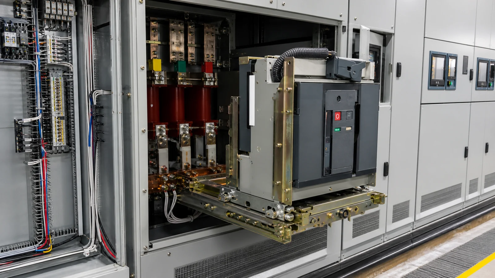
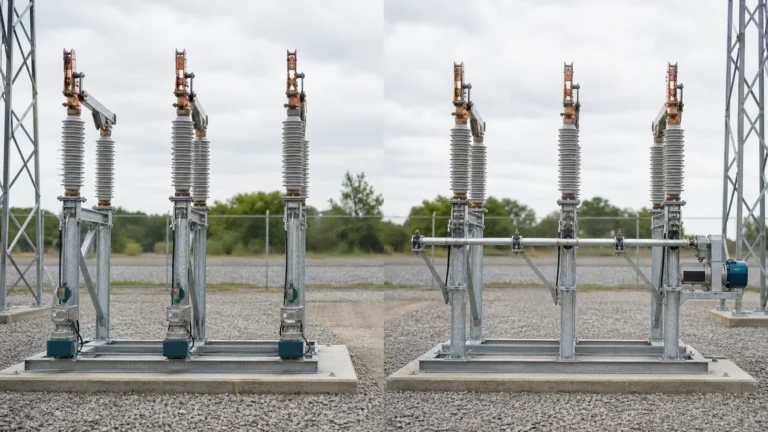
Figure 03: Cabinet and circuit-breaker interface review showing the physical location of relay panels, CT secondary wiring, VT secondary circuits, control bus, and auxiliary contacts — all of which require project-specific engineering before any settings are applied.
The protection interface section of a specification or submittal sheet may list the CT burden class available, the relay mounting space and terminal arrangement provided, the auxiliary power voltage for trip coils and control circuits, and the trip-circuit supervision provisions. None of these items constitute a protection scheme. They are the physical and electrical boundaries within which a protection engineer must design a scheme appropriate for the network topology, source configuration, load criticality, and coordination requirements of the specific installation.
No rating comparison is meaningful in isolation. The minimum document package that must accompany or precede switchgear specification includes a single-line diagram defining bus configuration and isolation philosophy; a short-circuit study report establishing available fault current at each bus; a load-flow report establishing maximum demand and power factor; a relay coordination study establishing time-current curves and backup clearing times; cable and transformer schedules providing impedance inputs; and the project specification establishing minimum rating margins, testing requirements, and acceptance criteria.
For compact secondary distribution points — such as those in the ring main unit class — the same document discipline applies regardless of the smaller physical footprint. The circuit breakers housed inside these assemblies carry their own nameplate data for interrupting rating and operating duty; those values must also be reconciled against study results, not read in isolation.
When commissioning acceptance is required, the governing reference hierarchy is: the project specification (defines minimum acceptable values and margins), the OEM installation and operation manual (defines test methods and thresholds for factory-tested parameters), insulation test data supplied with the equipment (defines the baseline for field insulation resistance and high-potential verification), and the factory test record or routine test certificate supplied with the assembly. No generic guidance document substitutes for those primary sources; they must be obtained, reviewed, and applied by a qualified person for each specific project.
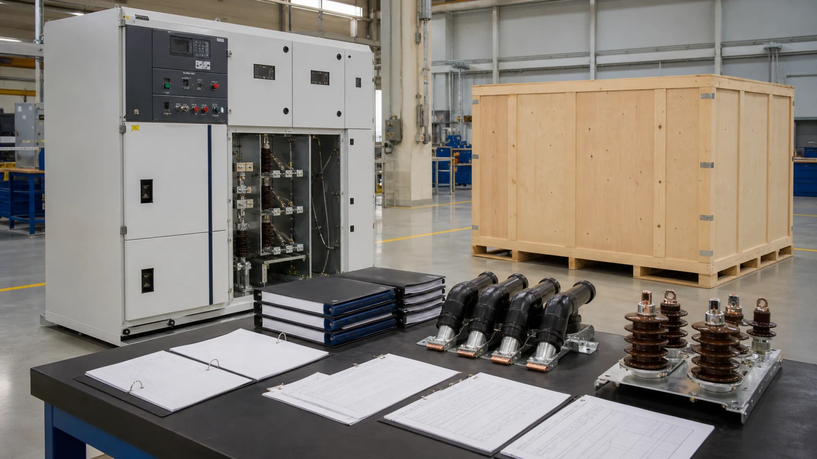
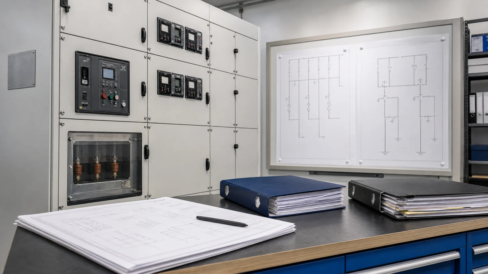
Figure 04: Buyer rating-data package and RFQ document set illustrating the inputs a manufacturer needs to verify that offered equipment ratings are appropriate for the described project — single-line diagram, study reports, specification, and site conditions.
| Rating Concept | What the Label Confirms | What the Label Does Not Resolve |
|---|---|---|
| Rated voltage | Maximum voltage class for which the equipment is designed and tested | Whether the actual system voltage, including tolerance and transient rise, fits within that class |
| Insulation level (BIL / power-frequency) | Dielectric withstand under standardized test conditions | Whether the surge environment and cable-termination method require a different class |
| Rated normal current | Continuous current capability at stated ambient and ventilation | Maximum demand current after load study, demand factor, and derating for actual ambient |
| Short-circuit withstand current | Mechanical and thermal integrity at rated fault current for rated duration | Actual available fault current at the installation bus from a short-circuit study |
| Short-circuit breaking current | Switching device interruption capability under standard test conditions | Whether that capability exceeds the calculated asymmetrical fault current at the device location |
| Rated duration of short circuit | Maximum withstand time before damage threshold | Whether relay operating time plus breaker opening time stays within that duration |
| Protection interface | Physical and electrical boundaries for relay, CT, VT, and control wiring | Protection scheme design, relay type, CT ratio, settings, and coordination |
The entries below are illustrative only. They do not represent measured values, confirmed field events, or engineering advice. They show the type of questions a reviewing engineer might raise during a preliminary document check, before detailed study work is complete.
| Symptom | First Test | Likely Cause | Next Action |
|---|---|---|---|
| Offered rated voltage class appears lower than the listed system nominal voltage | Cross-check system nominal voltage against the rated maximum voltage class definition in the applicable standard | Voltage class mismatch or document misread | Obtain updated SLD and utility voltage confirmation; refer discrepancy to engineer of record |
| Rated normal current appears close to projected peak demand with no visible margin | Review load study assumptions: ambient temperature, demand factor, growth projection, derating method | Insufficient margin or optimistic load estimate | Engage electrical engineer to recalculate demand including derating and growth; compare result to next available current class |
| Short-circuit study result approaches or exceeds rated short-circuit withstand current | Verify source impedance inputs, transformer rating, and motor contribution in the study model | Under-specified fault rating or study inputs updated after initial specification | Rerun short-circuit study with confirmed utility fault level; compare revised result against rated withstand |
| Rated duration of short circuit is shorter than the relay backup clearing time in the coordination study | Review coordination study for worst-case upstream backup clearing time under maximum fault condition | Protection clearing time too slow for equipment withstand duration | Engage protection engineer to adjust backup relay time-delay or evaluate equipment with longer withstand duration |
| CT burden class on the submittal does not match the relay input burden requirement | Review relay burden data at maximum secondary current from the relay manufacturer’s data sheet | Mismatched CT specification between relay study and switchgear order | Obtain confirmed relay burden from protection engineer; request CT class revision from manufacturer |
| Data Category | Specific Item Required | Source Document |
|---|---|---|
| System voltage | Nominal system voltage and permitted tolerance band | Utility interconnection agreement or current SLD |
| Overvoltage environment | Surge protection scheme, cable or overhead-line approach, arrester location | SLD and site survey report |
| Maximum load current | Peak demand after load study, demand factor, and all applicable derating | Load-flow study report |
| Available fault current | Symmetrical and asymmetrical fault current at each relevant bus | Short-circuit study report |
| Protection scheme requirements | Relay types, CT and VT class and burden, trip and close coil voltage | Relay coordination study |
| Enclosure environment | Ambient temperature range, altitude, pollution degree | Site conditions report |
| Installation constraints | Indoor or outdoor, space envelope, cable entry direction and quantity | Architectural and civil drawings |
| Project specification | Minimum rating margins, test requirements, and acceptance criteria | Project specification document |
No. A rated voltage class confirms the equipment was designed and tested for that class under standardized conditions. Whether the actual system voltage — including the utility’s permitted tolerance range and any anticipated transient or ferroresonant rise — falls safely within that class is a determination made by a qualified engineer reviewing site-specific data. The label is a necessary starting point; it is not a site-suitability certificate, and treating it as one bypasses the engineering analysis that identifies real risk.
Not directly. Rated normal current assumes a defined ambient temperature and a specified ventilation condition. If the actual installation ambient is higher than the rated value, or if enclosure ventilation differs from the rated condition, derating is required. The correct maximum allowable load current for a specific installation is the output of a load study and derating calculation performed against the project conditions and then compared to the rated value — it is not a figure that can be lifted directly from the nameplate.
Short-circuit withstand current (or short-time withstand current) is the current the bus assembly, enclosure, and all current-carrying parts can sustain for a rated duration without mechanical failure or inadmissible temperature rise. Short-circuit breaking current is the current the switching device — typically a circuit breaker — can safely interrupt. Both values must exceed the fault current calculated for the specific installation, but they address entirely different physical functions and should never be used interchangeably when reviewing equipment documentation.
At minimum: a current single-line diagram showing bus configuration and source arrangement; a short-circuit study report giving available fault current at each relevant bus; a load-flow report giving maximum demand; a relay coordination study establishing clearing times; cable and transformer impedance schedules; and the project specification defining minimum margins and acceptance criteria. Without these, any comparison of nameplate values to project requirements is incomplete. Once your document package is assembled, the XIYA POWER engineering team can assist in reviewing the complete switchgear cabinets range against your stated project data.
No. The switchgear assembly provides a physical and electrical interface for protective relays, current transformers, voltage transformers, and control wiring. The protection scheme — including relay type selection, CT ratio, pickup values, time delays, and coordination curves — is designed by a protection engineer based on the network topology, source configuration, load criticality, and coordination requirements of the specific installation. Settings are a project deliverable produced after a coordination study; they are not a factory label value and cannot be derived from nameplate data alone.
XIYA POWER manufactures medium-voltage switchgear for global distribution projects. For product specifications and project engineering support, contact the XIYA POWER technical team directly.