Quotation form
Send an inquiry
Start with the basics. Our team can follow up for missing drawings, standards or packing details.
Submitted details are used only for quotation, technical review and project communication.

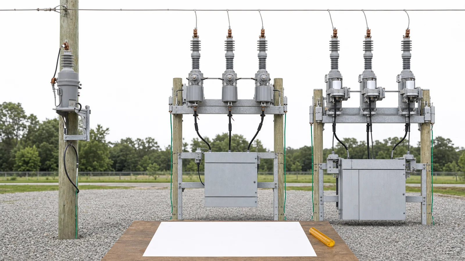
The single phase vs three phase recloser decision begins with the circuit and protected load at the installation point. Use a single-phase unit for a genuinely single-phase branch; study a gang-operated three-phase unit where all phases should operate together; and consider a triple-single or independent-pole package only where the feeder, loads, protection, control, and operating rules permit phase-selective operation. Device count alone does not decide the architecture.
This is not a choice between a universally “more reliable” and “safer” product. It is a controlled decision about fault-isolation boundaries, load consequences, trip/reclose/lockout modes, coordination, and operating authority. The recloser foundation owns the basic device definition; this guide focuses only on phase configuration.
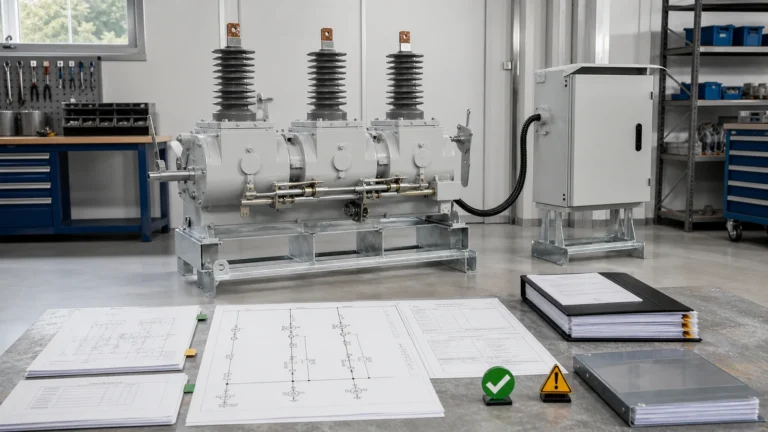
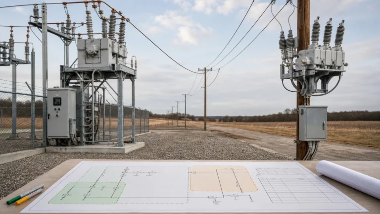
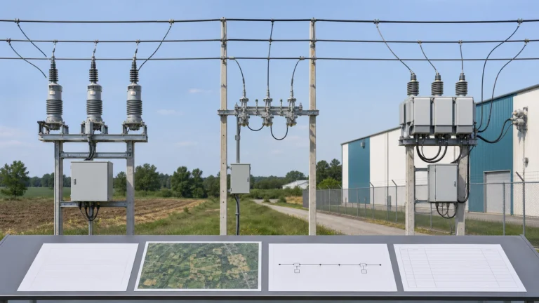
Visual transparency: Every image in this article is a generated illustrative technical visualization, not a XIYA POWER factory, customer, test, installation, or field photograph.
A single-phase recloser protects one single-phase circuit. Its sensing, interruption, reclose sequence, and lockout apply to that branch or tap. The XIYA POWER Single-Phase Recloser page shows this cutout-mounted branch role. Installing three separate units near one another does not automatically create an engineered three-phase scheme.
A gang-operated three-phase recloser opens, recloses, and locks out all three phases together through a common mechanism or coordinated operating scheme. This architecture gives the protected three-phase zone one all-phase state and can suit locations where three-phase loads should not remain connected to a partial-phase supply. The Automatic Vacuum Circuit Recloser page owns the feeder-class three-pole product context.
A triple-single or independent-pole three-phase recloser has three poles that can operate independently. Mechanical capability does not itself authorize single-phase operation. The controller may use single-phase trip and reclose for one condition, then three-phase lockout for another. A project-approved mode table must state the response to each fault type and abnormal state.
Eaton’s official recloser fundamentals similarly distinguishes single-phase branch/tap equipment, three-phase equipment where all phases operate together, and triple-single equipment with selectable phase modes. That public distinction is useful context, not a protection study or proof that a particular configuration fits a feeder.
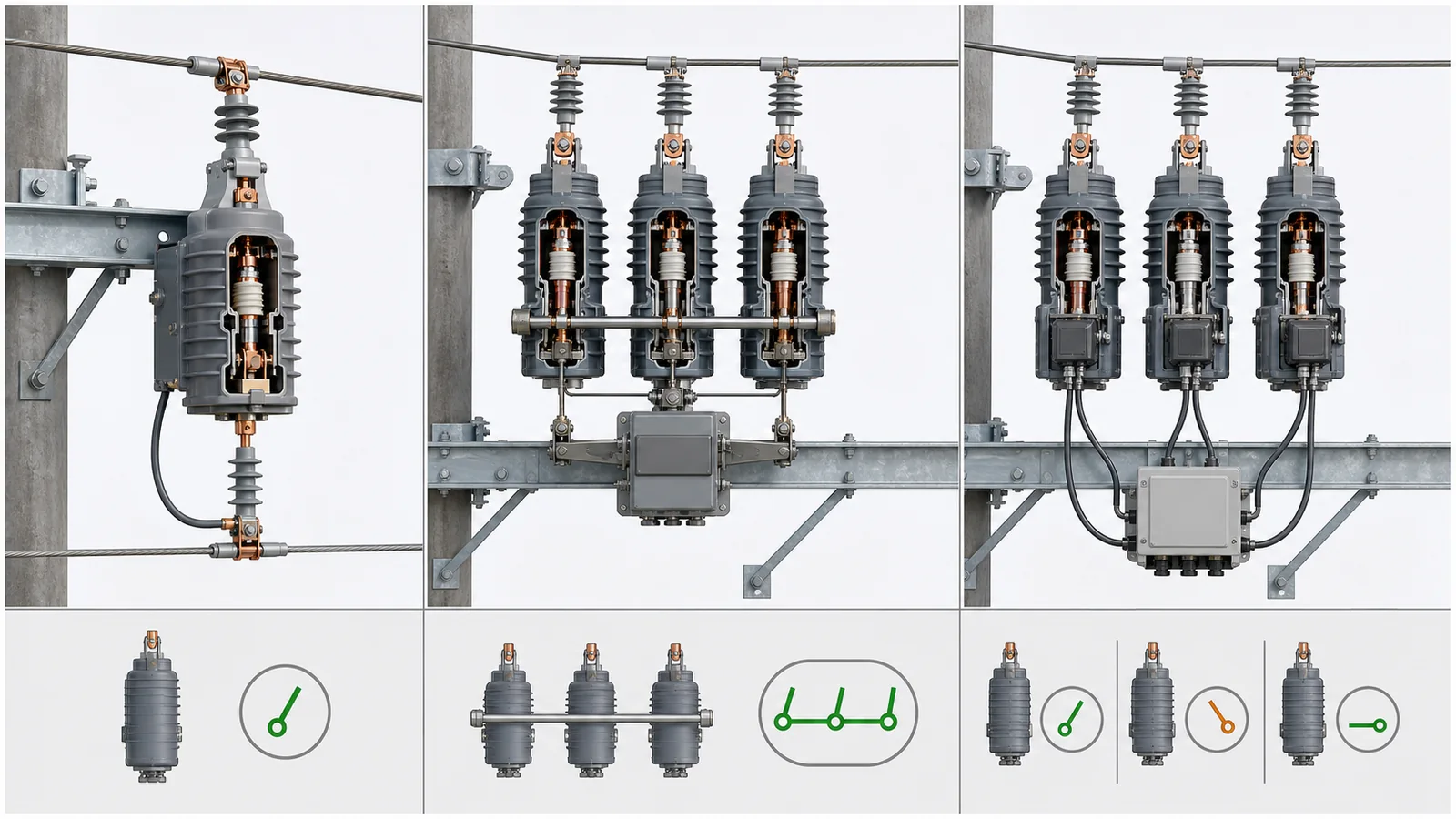
The Smart Grid equipment hub maps equipment to line roles. For the phase decision, use a selection matrix that makes every assumption and hold condition visible.
| Decision axis | Single-phase branch unit | Gang-operated three-phase | Triple-single / independent-pole |
|---|---|---|---|
| Circuit at point | Genuinely single-phase branch or tap | Three-phase feeder position | Three-phase position with phase-selective modes under study |
| Protected load | Single-phase branch loads | Mixed or three-phase zone requiring common state | Mixed zone with analyzed per-phase consequences |
| Isolation objective | Remove the affected branch | Open and restore all phases together | Select faulted phase where approved; otherwise all-phase action |
| Open-phase concern | Not a three-phase circuit at that point | Avoids a sustained partial-phase state downstream | Must be evaluated for motors, transformers, converters, DER, and protection |
| Coordination | Upstream source device and branch devices | Complete all-phase chain | Complete chain plus per-pole sensing, timing, and mode logic |
| Required evidence | Ratings, branch drawing, grounding, coordination | Feeder/load/fault studies, ratings, common operation, control | All three-phase evidence plus mode table, open-phase analysis, fail-safe and per-phase SCADA states |
| Hold condition | Branch role or coordination unresolved | Load consequence or coordination unresolved | Any three-phase gap plus unapproved mode or independent-pole evidence |
The matrix screens architectures; it does not select settings or predict reliability indices. Ratings, one-line, grounding, load profile, fault duty, coordination, controller behavior, and operating policy must all apply to the exact candidate position.
For this comparison, the phase-configuration RFQ checklist is deliberately narrow. Require the supplier to identify the physical pole architecture, common or independent mechanism, sensing per phase, supported trip/reclose/lockout modes, control-power dependencies, per-phase position feedback, and evidence applicable to the exact offered configuration. The project team must separately confirm the required input: current one-line, phase loading, grounding basis, phase requirements from the project specification, applicable short-circuit study, coordination behavior, protected-load constraints, and operating philosophy. Controlled manufacturer data and candidate-specific drawings can establish what the equipment is capable of; they cannot decide which capability the feeder is permitted to use. The complete commercial and technical RFQ belongs in the separate buyer-guide workflow.
Release evidence should map each proposed mode to its technical source, responsible reviewer, validation method, deviation status, and final approval. A catalogue checkbox for independent-pole operation remains open until the protection engineer confirms the feeder and load consequences. Likewise, a common-mechanism arrangement remains open until its ratings, all-phase interruption consequence, controller package, and restoration states have been accepted for the project.
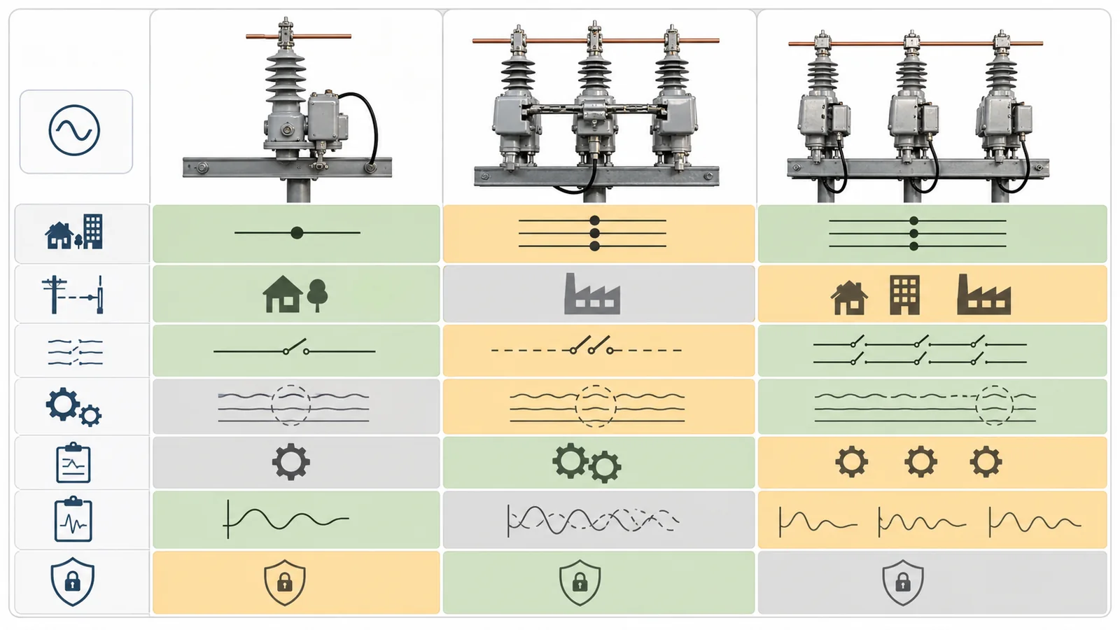
A phase-to-ground condition on a grounded four-wire feeder may be a candidate for single-phase isolation. A phase-to-phase or three-phase condition requires a coordinated multi-phase response. The approved mode table must define both cases instead of assuming every fault can use the preferred single-phase mode.
Four terms must remain separate: single-phase trip, single-phase reclose, single-phase lockout, and three-phase lockout. A scheme can trip and reclose one pole, yet open and lock out all three after it classifies a persistent condition. Calling this simply “single-phase operation” hides the most important load and restoration consequence.
Keeping other phases energized may reduce interruptions to compatible single-phase loads, but it is not an automatic benefit. Three-phase motors, transformers, converters, and DER may face unacceptable unbalance or open-phase conditions unless their protection and ride-through limits are confirmed. Energized adjacent conductors also affect isolation, work boundaries, and restoration rules. The utility or project protection owner must decide whether partial-phase operation is allowed and for how long.
No universal conclusion follows from the number of downstream customers or from the frequency of one fault type. The decision requires actual phase loading, grounding, fault behavior, three-phase load data, coordination, and approved operating procedures.
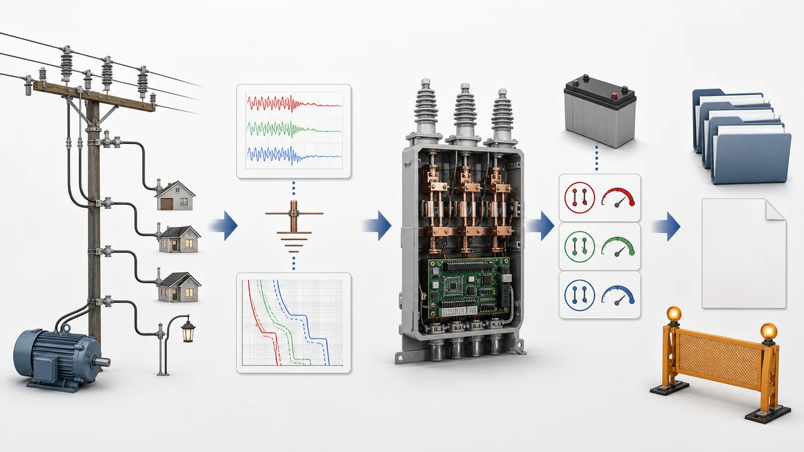
The state model must also cover more than normal closed and three-phase lockout. For an independent-pole package, document each pole’s commanded state, indicated physical state, protection state, communication quality, and behavior after a controller restart or loss of control power. Define what happens when one pole fails to follow a command, when sensing is unavailable on one phase, or when SCADA shows a partial-phase condition that field position indication does not confirm. These are system release questions, not assumptions to resolve after installation.
Build one evidence chain from feeder study to operating authority. Record only the deltas that can change the single-phase, gang-operated, or triple-single decision:
Three separate single-phase units must close the same chain before anyone treats them as an alternative to a factory-integrated triple-single package. Shared or coordinated sensing, mode logic, fault classification, timing, control power, records, and combined state handling cannot be inferred from having three interrupters.
This article does not provide trip thresholds, curves, reclose counts, dead times, synchronism settings, or switching instructions. Those belong to the approved study, device documentation, and authorized operating procedure.
A cutout-mounted single-phase unit has a branch-scale interface: one conductor/neutral arrangement, cutout geometry, branch load, mounting, and coordination with adjacent protective devices. A feeder-class three-phase package adds three-pole clearances, common or independent mechanisms, sensors, controller cabinet, control cables, power supply, communication equipment, bypass/isolation interfaces, and a larger controlled drawing set.
The protection owner must state who may approve or change phase mode, settings, and lockout philosophy. Operations must own per-phase indications, remote commands, alarms, restoration authority, and the response to disagreement between pole position and controller/SCADA state. Maintenance documents must define isolation boundaries and access without assuming that an open pole makes the other conductors safe.
The separate recloser vs circuit breaker decision determines which overall feeder architecture belongs at a position. Once the recloser architecture is selected, SG-04’s phase review determines whether its poles should operate as a single-phase branch device, a gang-operated three-phase set, or an approved independent-pole scheme.
Technical release should name the accountable study revision, drawing revision, controller/mode revision, evidence package, deviation register, and approval owner. A product description such as “single/three-phase capable” is a capability statement, not a released operating philosophy.
Representative engineering review only. All values and conditions below are illustrative and non-universal. This is not a XIYA POWER customer, utility, tender, factory, test, FAT, installation, commissioning, field, maintenance, fault, outage, restoration, or service case. No settings, installed outcome, or reliability improvement is claimed.
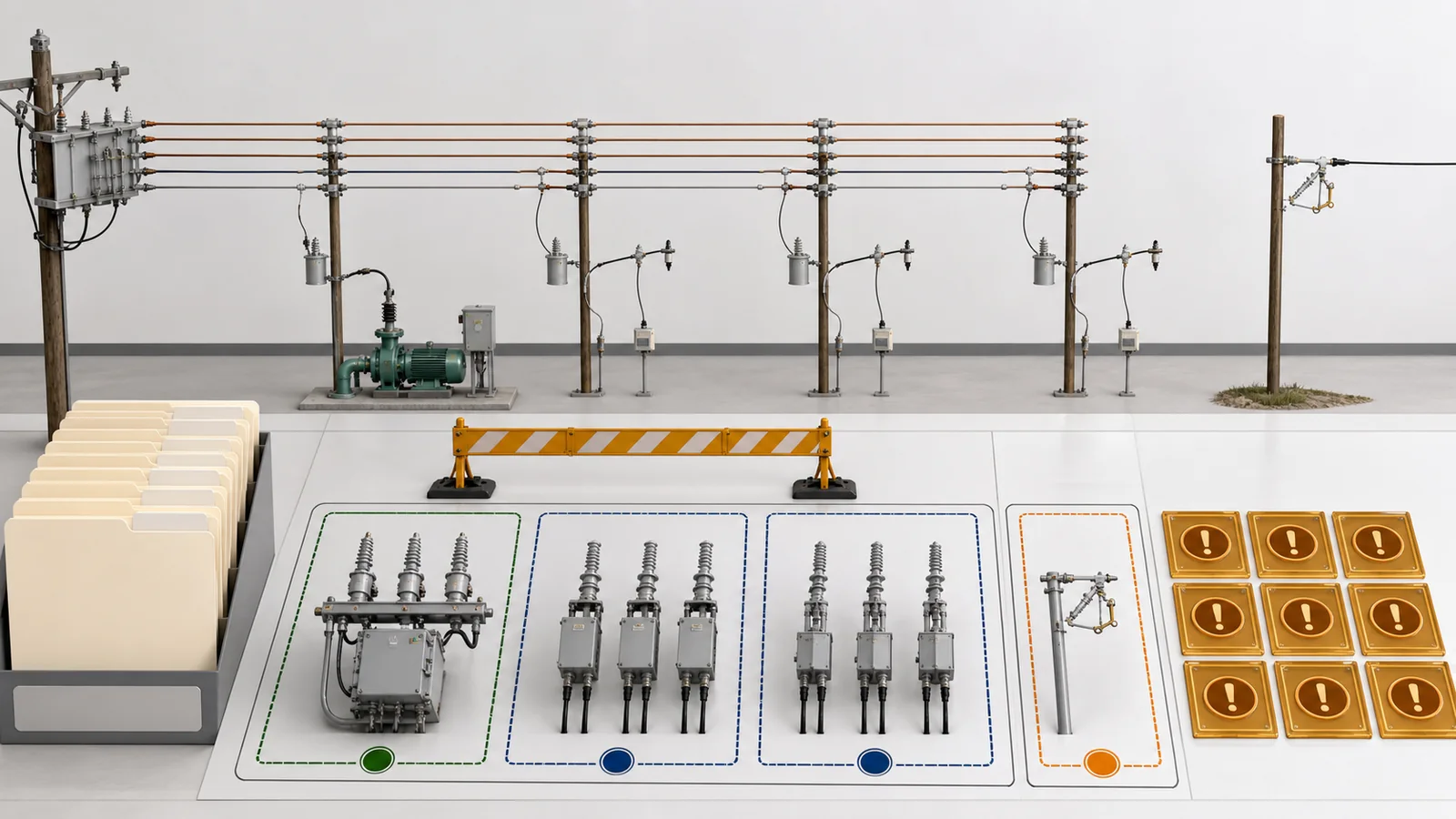
The illustrative system is a 12.47 kV, 60 Hz, four-wire grounded overhead feeder. A candidate three-phase mainline position feeds a mixed zone containing one three-phase pumping load and multiple single-phase laterals. A separate downstream tap is genuinely single-phase and currently uses a cutout position.
Three mainline options are screened: a gang-operated three-phase ACR; a triple-single independent-pole ACR with selectable modes; and three separately installed single-phase units. One cutout-mounted single-phase recloser is considered separately for the single-phase tap, subject to ratings and coordination.
Available records are the one-line, candidate data sheets, a preliminary load list, controller function lists, and pole arrangement drawings. The following remain missing:
The preliminary screen assigns the cutout unit only to the single-phase tap. The gang-operated and triple-single packages remain candidates at the three-phase point. Three loose single-phase units are not accepted as equivalent from device count alone.
Decision: hold final phase-configuration release. The responsible protection authority must close the load, grounding, fault, coordination, mode, control, evidence, and operating inputs before selecting the mainline architecture. Until then, neither the expected interruption impact nor the acceptability of keeping other phases energized is established.
Its clearest role is a genuinely single-phase branch, tap, transformer point, or boundary circuit. Applying phase-selective equipment on a three-phase mainline requires a three-phase system study and coordinated architecture; one single-phase unit cannot cover the other phases.
No. It may limit interruption for compatible loads during an eligible fault, but the result depends on topology, fault type, phase loading, grounding, downstream three-phase loads, coordination, and lockout policy. Do not claim an improvement without the applicable study.
All-phase operation may be required when downstream loads cannot tolerate partial-phase supply, a multi-phase fault is involved, coordination requires common clearing, or utility policy requires one three-phase state. The protection owner must approve the rule.
It is a three-pole package whose poles can be operated independently under controller logic. Its approved mode can still require three-phase trip or lockout. Per-pole capability is not permission to use every possible mode.
Not by device count alone. The proposal needs validated inter-phase sensing, fault classification, timing, mode logic, control power, fail-safe behavior, SCADA states, coordination, and operating rules before it can be considered an engineered three-phase scheme.
Provide the one-line, phase load profile, grounding, fault and coordination studies, downstream three-phase load constraints, candidate ratings, pole/control architecture, mode table, control-power behavior, SCADA states, drawings, restoration rules, and named approval owner.