Quotation form
Send an inquiry
Start with the basics. Our team can follow up for missing drawings, standards or packing details.
Submitted details are used only for quotation, technical review and project communication.

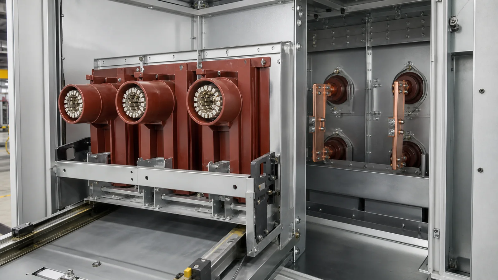
In medium-voltage metal-enclosed switchgear, a contact box and a wall bushing are both insulating interface components, but they solve different cabinet problems. A contact box surrounds and supports the fixed-contact side of a drawout vacuum circuit breaker (VCB) connection. A wall bushing provides an insulated passage for a conductor through a metal partition or phase barrier. This distinction is the starting point for understanding a contact box and wall bushing in switchgear.
The two parts may share a red or grey cast-resin appearance and may be offered for the same nominal voltage class. That does not make them interchangeable. Cabinet position, conductor geometry, mounting details, insulation envelope, electrical data, and approved drawings must all agree before a replacement is accepted.
This table is a first review, not a live-work instruction. Inspection and testing must follow the site’s isolation, earthing, access, and authorization procedures, then the OEM manual and project specification for the specific assembly.
| Symptom | First Test | Likely Cause | Next Action |
|---|---|---|---|
| Tracking marks or unusual deposits near a VCB fixed-contact opening | After approved isolation, inspect the contact-box surface and surrounding clearances | Contamination, surface damage, or an alignment issue at the contact interface | Record the condition; compare the part and cabinet drawings before cleaning, testing, or replacement |
| Damage or discharge evidence around a busbar partition | Inspect the wall-bushing flange, insulation surface, conductor passage, and nearby metal edges | Contamination, cracking, poor fit at the cutout, or inadequate clearance | Hold the assembly for engineering review and check the approved insulation and partition details |
| Abnormal temperature previously recorded at one VCB primary connection | Review the thermal record, then check the current-path condition under an approved test plan | Contact wear, poor engagement, conductor-joint issue, or contact-box misalignment | Verify contact centerline and engagement geometry before assigning the cause to the insulating part |
| Conductor does not align through a replacement bushing | Compare the cutout, bore, flange, and conductor centerline against drawings | Wrong bushing geometry or a cabinet/busbar configuration mismatch | Stop installation and obtain the correct drawing-matched part |
| Cracking, chipping, or discoloration is visible on a resin part | Isolate and document the damage; do not treat appearance alone as an acceptance test | Mechanical stress, contamination, thermal exposure, aging, or installation damage | Follow the OEM disposition process and project hold point before further testing or energization |
The easiest way to separate these components is to trace the current path and the cabinet partitions around it.
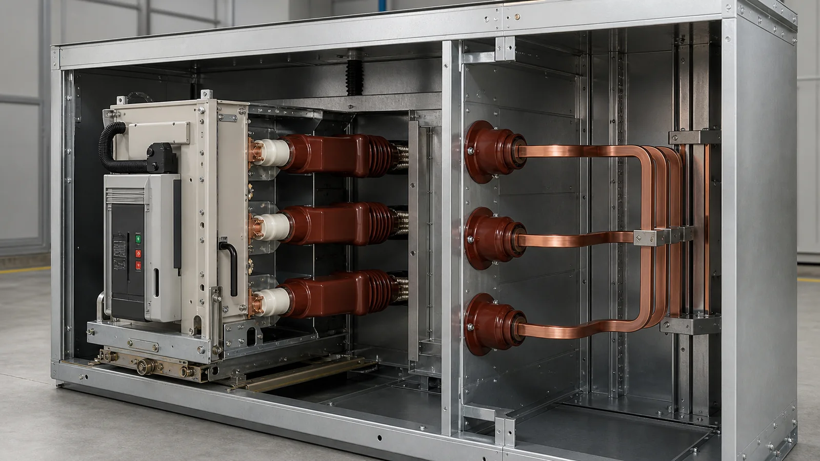
In a typical drawout metal-clad cabinet, including a KYN28-type switchgear arrangement, the VCB truck moves between disconnected, test, and service positions as defined by the cabinet design. Its primary contact arms approach fixed contacts at the rear of the breaker compartment. The contact box is the insulating body around that fixed-contact region. It helps locate the fixed-contact assembly and separates energized parts from earthed metalwork and adjacent phases.
The contact box is not the fixed contact, tulip contact, copper contact arm, VCB truck, or shutter. Those parts interact at the same interface, but each has a separate conductive, mechanical, or protective function.
Elsewhere in the cabinet, a busbar or cable-side conductor may cross a metal partition or phase barrier. The wall bushing creates the insulated passage at that boundary and may also support the conductor geometry. It is not the busbar, cable lug, or metal partition. Its job is to manage the conductor-to-partition interface within the assembly’s approved insulation arrangement.
A contact box combines mechanical location and insulation around a primary disconnect interface. It must fit the cabinet mounting plane while placing the fixed contact where the breaker contact arm is designed to meet it.
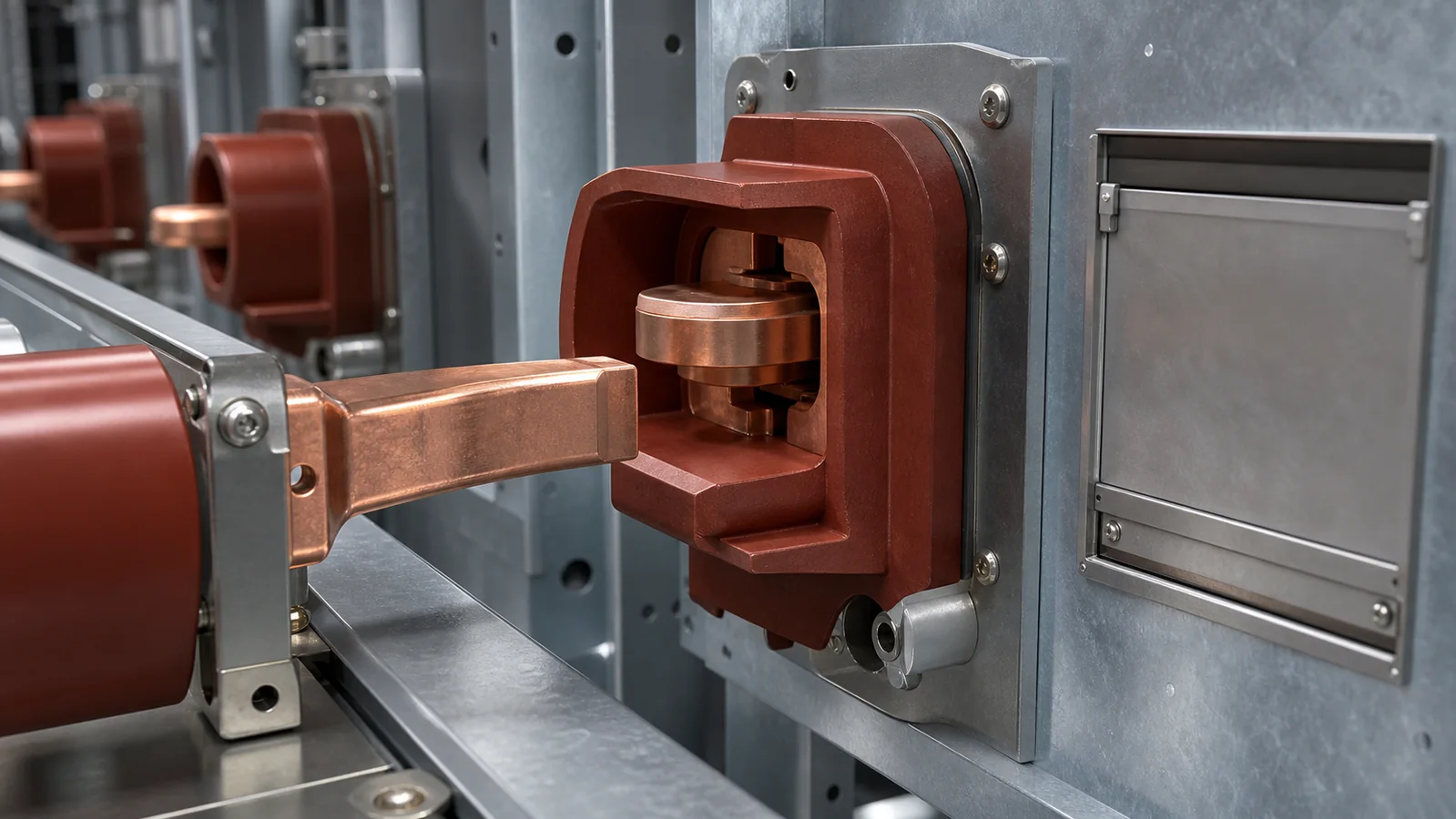
Several interfaces determine whether a replacement is suitable:
The XIYA POWER Contact Box product family uses model photos and drawing views as identification aids, then asks buyers to confirm cabinet position, voltage class, rated current, contact-box depth, interface direction, fixing dimensions, cabinet series, and old-part information. The drawing is used for dimensional matching; it should not be used to infer an electrical rating that is not stated in approved project data.
A wall bushing manages a different boundary: a live conductor passing through or alongside earthed metal or a phase-separation structure. Its geometry must coordinate with both the partition and the conductor system on each side.
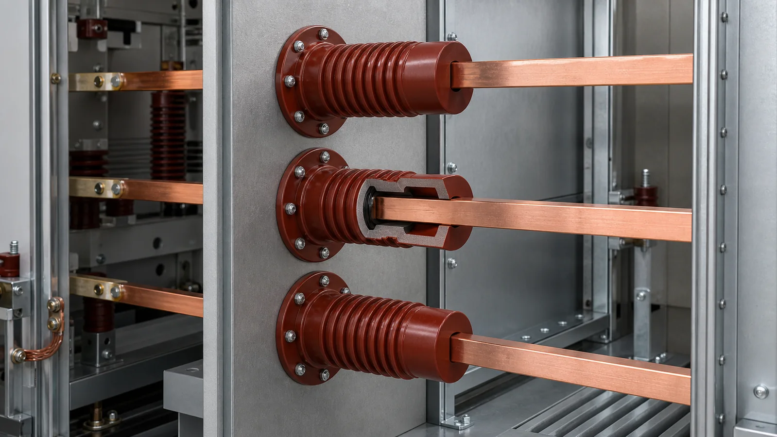
The matching review normally covers:
The XIYA POWER Wall Bushing product family therefore asks for flange size, through-hole diameter, fixing geometry, insulation length, panel cutout, conductor centerline, phase spacing, busbar arrangement, creepage requirement, mounting clearance, and cabinet data. A matching bore alone is not enough.
| Review Point | Contact Box | Wall Bushing |
|---|---|---|
| Primary cabinet role | Insulates and positions the fixed-contact region of a drawout VCB interface | Insulates a conductor passage through a partition or barrier |
| Adjacent current-path parts | Fixed contact, tulip/contact cluster, breaker contact arm, rear conductor | Busbar, cable lug, tubular conductor, or other cabinet conductor |
| Key mechanical reference | Breaker-compartment mounting plane and contact centerline | Partition cutout, flange plane, and conductor centerline |
| Typical mismatch risk | Incorrect engagement depth, hole pattern, orientation, or shutter clearance | Incorrect flange/cutout, bore, phase pitch, insulation profile, or adjacent clearance |
| Approval basis | Breaker and cabinet drawings plus released electrical data | Partition, conductor, and cabinet drawings plus released electrical data |
This is representative engineering reasoning, not a XIYA POWER customer project, commissioning event, or measured field record. The measured dimensions below are fictional comparison inputs.
Assume two red epoxy contact boxes come from different cabinet families in the same nominal voltage class. Their outside diameters differ by 4 mm, their front openings look nearly identical, their fixing-hole pitches differ by 8 mm, and their contact centerline depths differ by 6 mm.
A photo-led review might focus on the similar opening. A drawing-led review identifies two independent blockers: the mounting pattern does not match, and the fixed contact would sit at the wrong depth. Elongating holes would not solve the second problem and would introduce an unapproved mounting change. Even if the breaker truck could be racked in, the contact engagement could differ from the released design. The correct action is to stop the substitution and compare the old part, cabinet position, contact system, and approved drawings.
The same reasoning applies to a wall bushing. Two parts may share a bore diameter yet have different flange patterns, conductor centerlines, surface profiles, or partition clearances. Each mismatch affects a different interface, so no single catalogue dimension can establish compatibility.
The component itself does not define every acceptance limit. The complete assembly documentation must determine what is inspected, how it is tested, and who releases it.
| Check | Tool or Evidence | Acceptance Source | Result Handling |
|---|---|---|---|
| Visual and dimensional condition | Approved drawing, calibrated dimensional tools, photographs | Drawing tolerances and OEM manual | Record any deviation and raise a corrective action before approval |
| Insulation condition | Inspection and only the insulation test method authorized for the assembly | OEM manual, project specification, and released test procedure | Compare with the stated limit and retain the test record |
| Contact-path condition | Alignment review and contact resistance measurement where specified | OEM manual, project specification, and approved baseline | Investigate the complete joint and contact system, not only the contact box |
| Creepage and clearance arrangement | Drawing comparison and dimensional verification | Approved cabinet layout and insulation-coordination documents | Stop release if the installed geometry differs from the approved arrangement |
| Fastening and mechanical fit | Seating inspection and calibrated torque tooling where required | OEM manual and released assembly instructions | Correct the installation only through the approved corrective action process |
IEC 62271-200:2021 applies to prefabricated AC metal-enclosed switchgear and controlgear above 1 kV and up to and including 52 kV. It addresses the assembled switchgear; it is not a catalogue of interchangeable contact-box or wall-bushing dimensions. Component approval still depends on the OEM documentation, cabinet drawings, project specification, and released verification plan for the assembly.
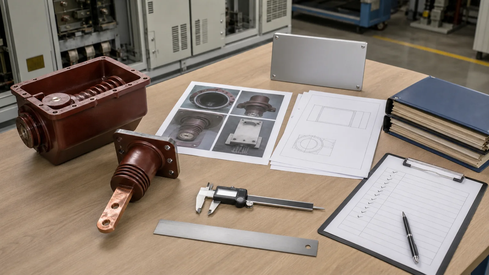
Start with evidence from the installed position. The switchgear components range can provide model references, but the RFQ should contain enough information for an engineering match rather than asking for a part based on color and a single photo.
For either component, provide:
For a contact box, add mouth geometry, mounting-plane dimensions, fixing-hole pattern, contact centerline and depth, terminal orientation, phase arrangement, and the associated breaker/contact-system data.
For a wall bushing, add flange and cutout dimensions, partition thickness, bore geometry, conductor type and size, conductor centerline, phase spacing, insulation-body length, surface profile, and available clearance around the installed conductor.
Before purchase release, compare the supplier drawing with the cabinet drawing line by line. Mark every dimension and interface as confirmed, open, or not applicable. Resolve open items before manufacturing or installation, then retain the approved drawing and any required test record with the equipment documentation.
No. Voltage class is only one part of the insulation and equipment data. A contact box belongs to a drawout breaker’s fixed-contact interface, while a wall bushing belongs to a conductor passage through a partition. Their mounting, conductor, and mechanical functions are different.
Color and approximate shape do not show the contact centerline, mounting depth, hole pitch, bore, flange, conductor interface, creepage profile, or cabinet clearance. Those drawing-controlled details determine whether the part fits the intended assembly.
Use the existing part outline, breaker primary-interface drawing, and cabinet compartment drawing. Together they should identify the mounting plane, opening, fixed-contact location, engagement geometry, fixing pattern, conductor connection, phase spacing, and available clearance.
It establishes requirements for the complete metal-enclosed switchgear assembly within its scope. It does not make individual insulating parts universally interchangeable. The selected component must fit the OEM and project-specific assembly design used to meet those requirements.
Provide old-part photos, cabinet identity and position, electrical data, flange and cutout dimensions, partition thickness, bore and conductor geometry, centerline and phase spacing, insulation profile, quantity, and available drawings. Missing dimensions should be identified as open engineering items, not guessed.
A contact box positions and insulates a VCB fixed-contact interface; a wall bushing insulates a conductor passage through a cabinet partition. That functional distinction tells you which drawing set to open. Final approval comes only after the component, conductor, mounting, insulation, and cabinet interfaces agree with the released project documentation.



