Outdoor disconnect switch types

Outdoor Disconnect Switches for Visible Line Isolation

Compare seven outdoor disconnector structures for visible no-load isolation, neutral protection and outdoor line maintenance points. Use this page to choose the switch body, open-break geometry, mounting context and project data before model selection.

Send Project Details
Product types

Outdoor Disconnect Switch Types

Start from the physical switch structure: rotary, single-pole, neutral gap, double-break, non-fuse, three-phase or V-type. Each product entry keeps the required project data beside the product options.
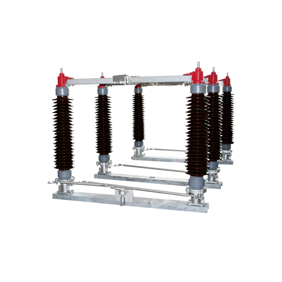
Double-column horizontal rotary disconnector product on a clean white background
ODS 01Product type

Double-column Horizontal Rotary Disconnector, 10 kV-220 kV

High-voltage outdoor visible isolation for substations, overhead line isolation points and maintenance switching positions.
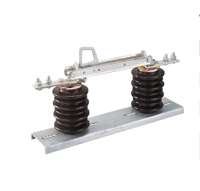
Medium voltage single-pole isolation switch with porcelain insulators on white background
ODS 02Product type

Medium Voltage Single-pole Isolation Switch

Medium-voltage single-pole isolation for overhead distribution lines where pole-by-pole switching and compact mounting matter.

ODS 03Product type

Neutral Disconnector with Gap Protection

Neutral-point isolation and gap-protection coordination for transformer neutral or special grounding arrangements.

Send details
ODS 04Product type

Rotary Double Break Isolator Switch

Outdoor double-break isolation where the buyer needs a rotating contact arrangement and compact structure-based selection.

Send details
ODS 05Product type

Single-phase Isolation Switch, Non-Fuse Type

Single-phase non-fuse isolation for overhead line points where protection is handled by another device.

Send details
ODS 06Product type

Three-phase Disconnecting Switch

Three-phase outdoor disconnection for overhead line or structure-mounted isolation points.
Send details
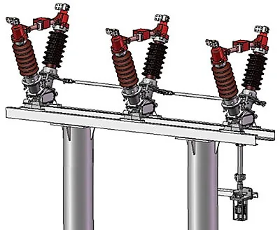
V-type horizontal break outdoor isolator with three-pole V structure on white background
ODS 07Product type

V-type Structure Horizontal Break Outdoor Isolator

V-type or horizontal-break outdoor isolation for high-voltage line and substation positions with structure-specific clearance needs.

Project details

Send the selected type with voltage, current and mounting drawing.

Select a product type, then send voltage class, rated current, operating method, mounting drawing, quantity and destination standard.

Send details
Technical parameters

Neutral Disconnector with Gap Protection Technical Data

Complete neutral point protective device data from the available BZJ-150 and BZJ-220 reference material.

Reference basisBZJ-150 / BZJ-220 Neutral Point Protective Device

The reference material describes a transformer neutral point protective device composed of a neutral point disconnector, discharge gap, zinc-oxide arrester and current transformer for discharging-current measurement.

The package is used when transformer neutral over-voltage protection and insulation coordination require a defined gap, arrester and isolation switch layout.

Reference coverage
BZJ-150 / BZJ-220 neutral point complete protective device
Transformer rating class
150 kV class uses 170 kV transformer voltage; 220 kV class uses 252 kV transformer voltage
Disconnector series
GW13-150 / GW8-150 and GW13-126 / GW8-126
Arrester series
YH1.5W-96/260 and YH1.5W-144/320
Discharge gap
Rod clearance / spherical electrode
Current transformer
LMZW-10 current transformer option
Operating mechanism
CS17A manual mechanism or CJTKB motor mechanism
Support structure
T-shaped or n-shaped steel support, hot-galvanized structure

Operating and Installation Environment

ItemReference value
Ambient temperature-50 deg C to +50 deg C
AltitudeNo more than 2000 m; 2500 m or more can be adapted by requirement
Wind pressureNo more than 700 Pa, equivalent to 34 m/s wind speed
Seismic intensityNo more than 9 degrees
Ice coating thicknessNo more than 20 mm
Environment pollution classIII and IV
Installation siteFree of combustible, explosive hazard, chemical corrosion and violent movement

Transformer Neutral Point Withstand Voltage

ItemUnitBZJ-150BZJ-220
Rated voltage of transformerkV170252
8/20 us lightning impulse withstand voltagekV peak272400
1 min power frequency withstand voltagekV peak137200

Disconnector and Arrester Parameters

ItemUnitBZJ-150BZJ-220
Disconnector typeGW13-150 / GW8-150GW13-126 / GW8-126
Disconnector rated currentA630630
Resistance on main loop circuitmicro-ohm450450
Insulation distance across open contact after openingmm>=900>=1000
Operation mechanismCS17A manual or CJTKB motorCS17A manual or CJTKB motor
Zinc-oxide arrester typeYH1.5W-96/260YH1.5W-144/320
Arrester rated voltagekV r.m.s.96144
Continuously operating voltagekV r.m.s.77116
8/20 us lightning impulse current residual voltage, no more thankV260320
DC 1 mA reference voltage, no less thankV134205
2 ms square-wave flow capacityA400400

Discharging Clearance and Current Transformer

ItemUnitBZJ-150BZJ-220
Discharging clearance typeRod clearance, spherical electrodeRod clearance, spherical electrode
Power frequency dry discharging voltage +/-10%kV110164
Clearance electrode distance rangemm135-230250-320
Current transformer typeLMZW-10LMZW-10
Current variation ratio200/1, 200/5, 300/5, 400/5, 1000/5200/1, 200/5, 300/5, 400/5, 1000/5
Secondary protection level5P/30, 10P/10, 10P/205P/30, 10P/10, 10P/20
CapacityVA10, 20, 3010, 20, 30
Weight, no more thankg350400
Weight summarykgNo more than 350 / 400No more than 350 / 400

Main Feature Notes

FeatureReference note
Integrated setComplete protective device makes installation quick and convenient
Discharge clearanceIndependent stainless-steel component with adjustable clearance
Mounting preparationInstallation screw holes are prepared after disconnector and arrester types are confirmed
Steel supportHot-galvanized steel structure for solid support and corrosion prevention
Manual mechanismCS17A manual mechanism with stainless-steel cabinet; electromagnetic lock can be installed if required
Motor mechanismCJTKB motor mechanism with stainless-steel case, sealing and interlocking capability
Complete neutral disconnector and gap protection set on a clean white background
Complete neutral point protection set
Neutral point protection layout with disconnector arrester gap and counter assembly
Neutral protection layout with gap and counter
Reference basis

Neutral point technical material is shown as buyer-facing rating tables and cleaned drawing views. Chinese labels and screenshot-only material are not shown.

Installation dimension drawing
Compact neutral layout drawing
Technical parameters

Rotary Double Break Isolator Switch Technical Data

GW7-126 and GW7-252 rotary double-break outdoor disconnect switch data from the available technical references.

Reference basisGW7-126 / GW7-252 technical references

GW7-126 is described as a three-phase AC 50 Hz outdoor high-voltage disconnect switch for visible electrical isolation under no-current carrying conditions.

GW7-252 is a three-pole structure with frame, post insulators and conducting parts. The operating mechanism drives the revolving insulator about 71 degrees for opening and closing.

Reference coverage
GW7-126 Outdoor Disconnect Switch and GW7-252 Outdoor HV Disconnect Switch
Rated voltage
126 kV / 252 kV
Rated current
GW7-126: 5000 A; GW7-252: 2000 / 2500 / 3150 / 4000 A
Rated peak withstand current
GW7-126: 160 kA; GW7-252: 125 / 160 kA
Rated short-time withstand current
GW7-126: 63 kA; GW7-252: 50 / 63 kA
Insulation level
1 min power-frequency withstand 460 kV; lightning impulse withstand 1050 kV references
Mechanism options
CJ6A / CSA and CJ6B motor / CS17 manual mechanism references
Environment
Altitude <=2000 m, -40 C to +40 C, wind <=34 m/s, ice <=10 mm
Standards reference
IEC 62271-102 and GB1985

GW7-126 Main Technical Parameters

No.ItemUnitData
1Rated voltagekV126
2Rated currentA5000
3Rated peak withstand currentkA160
43 s rated short-time withstand currentkA63
5Rated frequencyHz50
6Grounding switch rated peak withstand currentkA160
6Grounding switch 3 s short-time withstand currentkA63
7Terminal rated pull force, longitudinalN1500
7Terminal rated pull force, horizontalN1000
7Terminal rated pull force, verticalN1250
8Rated insulation level, 1 min power-frequency to earthkV460
8Rated insulation level, 1 min power-frequency fracturekV460+145
8Lightning impulse withstand voltage to earthkV1050
8Lightning impulse withstand voltage fracturekV1050+200
9Electromagnetic coupling rated inductive currentA80
9Electromagnetic coupling rated inductive voltagekV2
9Electrostatic coupling rated inductive currentA3
9Electrostatic coupling rated inductive voltagekV12
10Post insulator creeping ratio distance, III / IVmm/kV25 / 31
11Mechanical lifetimes3000
12Disconnecting switch circuit resistancemicro-ohm50
13Open and close bus conversion currentA1600
14Single pole weightkg1020

GW7-126 Working Environment

ItemReference value
AltitudeDoes not exceed 2000 m
Ambient temperature-40 deg C to +40 deg C
Maximum wind speed34 m/s
Anti-seismic abilityHorizontal acceleration 0.250 g; vertical acceleration 0.125 g
Ice thicknessNo more than 10 mm
Insulator pollution levelIII at 25 mm/kV; IV at 31 mm/kV
Installation siteFree from flammable, explosive, chemical corrosion and frequent severe vibration

GW7-252 Technical Specification

No.ItemUnitData
1Rated voltagekV252
2Rated currentA2000 / 2500 / 3150 / 4000
3Rated peak withstand currentkA125 / 160
4Rated short-time withstand current with earth switchkA50 / 63
5Rated short-time withstand times3
61 min P.F. withstand voltage to phasekV460
71 min P.F. withstand voltage across open contactkV460+145
8Rated lightning impulse withstand voltage to phasekV1050
9Rated lightning impulse withstand voltage across open contactkV1050+200
10Weight for single polekg500
11Mechanism operating timestimes3000
12Mechanism type, main bladeCJ6A
12Mechanism type, earth bladeCSA

GW7-252 Ambient Condition

ItemReference value
Altitude<=2000 m
Ambient temperature-40 deg C to +40 deg C
Wind speed<=34 m/s
Earthquake intensity<=8 degree
Ice coverage thickness<=10 mm
Pollution degreeI, II, III, IV
Applicable occasionFree from inflammables and frequent severe vibration

CJ6B motor / CS17 manual mechanism

ItemUnitCJ6B motorCS17 manual
Main axes output angledegree18090
Rated output torqueN.m1200
Motor powerW750
Motor voltageVAC380, DC220
Motor rated current / start currentA1.3 / 4
Motor rotate speedr/min1440
Control voltageVAC220, DC220
Anti-pollution degreeIP54IP54
Mechanical lifetimes1000010000
Contact of auxiliary switchpair10NO+10NC4NO+4NC, 8NO+8NC
Opening/closing times5 +/- 1 s30 s
Mechanism weightkg90

GW7-252 Structure and Operating Notes

AreaReference note
StructureThree-pole structure with frame, post insulators and conducting parts; each pole uses three post insulators
Rotating contact arrangementRevolving post is installed on the center axis base; the conductive knife is fixed on the center revolving post insulator
Operating mechanismMechanism drives the post insulator revolving 71 degrees to finish closing
InterlockInterlock is provided between disconnect switch and earth switch
Driving partSelf-lubricating composite axis cover; no added lubricating oil required
Main electric systemContact finger silver coating thickness >=30 um; hardness >=120 Vickers
Rotary double break isolator switch product on white background
Clean rotary double-break isolator product image
Reference basis

GW7-126 and GW7-252 values are shown as text tables with cropped, English-oriented technical visuals.

GW7-126 installation dimension drawing
GW7-252 model code and configuration key
Technical parameters

Single-phase Non-Fuse Isolation Switch Technical Review

Technical review for the non-fuse single-phase isolation switch photos. The available material confirms structure, not a standalone electrical rating table.

Reference basisPhoto-based reference only – no independent rating table available

The available material contains three product photos and no parameter table. The technical note therefore keeps to confirmed structure signals only.

Voltage and current selection belongs under the single-pole isolation switch product type, where the actual rating and insulation variant can be matched.

Confirmed reference content
Three product photos showing the switch body and mounting structure
Function
Non-fuse blade isolation
Phase count
Single phase / single pole
Duty boundary
Visible no-load isolation only
Insulator body
Polymeric-looking outdoor insulator body in selected photos
Contact structure
Blade contact with terminal hardware
Mounting interface
Vertical pole bracket or support strap
Operation
Hook-stick operation ring / manual operating eye
Rating table status
No independent rating table available

Photo-Based Technical Review

Review signalConfirmed valueSelection note
Product formSingle-phase non-fuse isolation switchKeep selection under the main single-pole isolation switch data until a rating table is available
Switch bodyNon-fuse blade isolation with fixed bracket hardwareSpecify fuse duty on the Fuse Disconnect Switches page instead
Phase configurationSingle phase / single poleUse for one-pole line isolation positions
Operation interfaceHook-stick operation ringManual operation confirmed by reviewed photo
Mounting interfaceVertical pole bracket or support strapMounting drawing is still required for final selection
Rating tableNo independent rating table availableSelect voltage and current under the single-pole isolation switch product type
Single-phase non-fuse isolation switch selected clean product photo
Selected clean non-fuse isolation switch photo
Single-phase non-fuse isolation switch side structure and bracket detail
Side structure and pole-bracket detail
Reference basis

Available photos support product-structure review only. No voltage or current rating is invented from photos.

Drawing requirement

Request an outline or mounting drawing during technical review when fixed dimensions matter.

Technical parameters

Three-phase Disconnecting Switch Technical Data Review

Reference-limited technical note for the three-phase disconnecting switch visuals. The reviewed material confirms product form and duty boundary, but does not include a standalone rating table or clean drawing sheet.

Reference basis9 reviewed images; no dedicated specification table found

The reviewed visual material shows a three-pole outdoor disconnector / vertical isolator structure for grouped visible isolation points.

Fuse combination and arc/load-break images were excluded so this product stays inside the outdoor disconnect switch duty boundary.

Reference material
Three selected clean product visuals from 9 reviewed images
Product form
Three-phase outdoor disconnecting switch / vertical isolator structure
Phase count
Three phase / three pole assemblies
Duty boundary
Visible no-load isolation; do not present fuse or load-break duty for this product type
Main structure signal
Base frame, three pole assemblies, conductive blades and linkage hardware
Visual variants
Three-phase disconnector plus vertical type outdoor isolator references
Drawing requirement
Request outline or mounting drawings when fixed dimensions matter
Rating table status
No independent voltage, current, BIL or short-time current table found in the reviewed material

Reference-Limited Technical Review

Review signalConfirmed valueSelection note
Product formThree-phase outdoor disconnector / vertical isolatorConfirm a model sheet before treating it as a model-specific offer
Pole arrangementThree visible pole assembliesSuitable for grouped three-phase isolation review
StructureBase frame, insulators, conductive blades and linkage hardwareFinal mounting structure still needs a project drawing
Selected visualsThree clean product viewsUse these photos as the confirmed visual references
Excluded duty groupOutdoor High-Voltage Fuse Combination DisconnectorFuse-combination duty belongs on the Fuse Disconnect Switches page
Excluded arc visualArc/load-break equipment viewDo not mix arc-chute/load-break messaging into this disconnect switch product
Electrical ratingsNot listed in reviewed materialDo not infer voltage, current, BIL or short-time current from photos
Drawing packageNot listed in reviewed materialConfirm mounting drawing during technical review
Three-phase disconnecting switch product on a clean white background
Selected clean three-phase disconnecting switch photo
Vertical type outdoor isolator product on a clean white background
Vertical type outdoor isolator reference
Three-phase vertical outdoor isolator product reference on a clean white background
Large vertical isolator reference photo
Reference basis

The reviewed material only confirms visual form and structure signals; no voltage, current or drawing values are invented.

Drawing requirement

Request an outline or mounting drawing during technical review when fixed dimensions matter.

Application fit

Visible Isolation Applications

Outdoor disconnect switch selection starts with the isolation point: overhead line, substation structure, neutral point or pole-mounted maintenance point. Use this section to avoid mixing no-load isolation with load switching or fuse protection.

Engineering topology

Read the isolation point before choosing the switch body.

The topology board supports visual scanning. Final selection still follows voltage, current, mounting drawing and duty boundary.
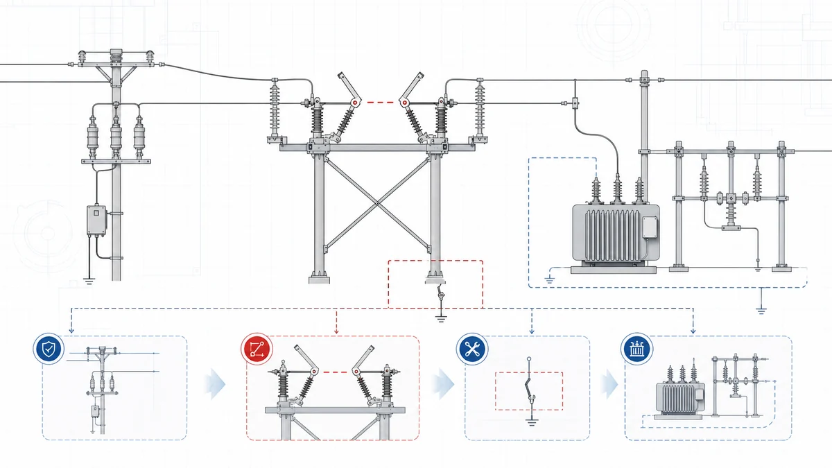
Engineering topology diagram for outdoor disconnect switch isolation point selection
Line isolation

Visible open point for maintenance

Use outdoor disconnect switches after load or fault current has been removed by upstream switching or protection equipment.

Substation isolation

Structure and clearance driven selection

Double-column, rotary double-break and V-type structures are selected by voltage level, open distance, phase spacing and support structure.

Neutral protection

Neutral point and gap coordination

Neutral disconnector with gap protection needs transformer neutral scheme, gap or arrester arrangement and drawing review before quotation.

Selection matrix

Outdoor Disconnect Selection Matrix

Compressed engineering view: application point, structure signal and required project data. Product photos stay in the section above.

Product type
Application point
Structure signal
Project data
Double-column rotary10 kV-220 kV
HV substation/Visible gap/Line maintenance
Double-column/Horizontal rotary/Grounding blade
Voltage/Current/Grounding/Drawing
Single-pole isolation15 kV / 33 kV
Distribution pole/Pole-by-pole/Compact mount
Single pole/Porcelain / epoxy/Bracket style
Voltage/Insulator/Current/Bracket
Neutral gap protectionNeutral point
Transformer neutral/Gap protection/Grounding scheme
Gap layout/Arrester option/Support height
Neutral scheme/Gap/Drawing/Height
Rotary double breakDouble break
Substation bay/Double open point/Compact layout
Two breaks/Rotary contact/Operating side
Voltage/Current/Contact arrangement/Base
Single-phase non-fuseNon-fuse
Single phase/No fuse/Line isolation
Blade contact/Pole bracket/Manual operation
Voltage/Current/Bracket/Quantity
Three-phase disconnectingThree phase
Grouped operation/Overhead line/Shared linkage
Phase spacing/Linkage/Arc option
Voltage/Current/Spacing/Mechanism
V-type horizontal breakHV clearance
HV line/Clearance driven/Substation structure
V-type/Horizontal break/Grounding option
Voltage/Current/Clearance/Drawing
Structure

Structure and Mounting Inputs

Confirm drawing, operation and mounting inputs before final configuration.
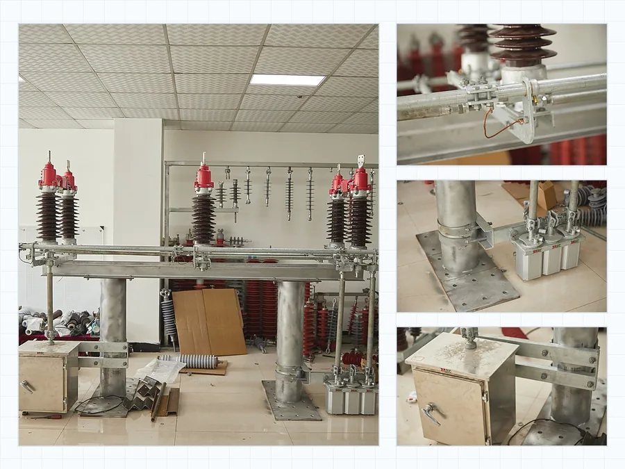
Outdoor disconnect switch structure details for visible isolation review

Structure inputs

Four checks before final configuration.

Visible gapOpen distance, break count, contact arrangement.
Support systemInsulator type, base frame, terminal load.
Operating packageManual, motor, linkage, handle side.
Mounting fitPole, steel frame, phase spacing, grounding.
Variant handling

Voltage and Duty Boundaries

After the switch structure is clear, confirm the rating, insulation material and duty boundary that change the final configuration.

Rating options

Choose voltage class and insulator material inside the same switch type.

15 kV, 33 kV, epoxy, polymeric and porcelain options stay under the single-pole isolation switch so the project data compares equal structures first.

Duty boundary

Separate visible isolation from fuse or load-switching duty.

Use outdoor disconnect switches for no-load isolation. Add fuse-combination or load-break requirements only when protection or current interruption is required.
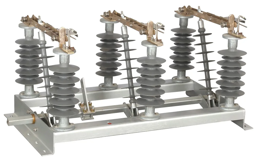
Medium voltage single-pole isolation switch with porcelain insulators on white background
Three-phase outdoor disconnecting switch product on white background
V-type horizontal break outdoor isolator with three-pole V structure on white background
Review files

Outdoor Disconnect Documents

A complete technical file lets engineering confirm structure, ratings, operating side and mounting clearance from more than product photos alone; teams can also download outdoor disconnect switch catalog PDFs before final model review.

Double-column horizontal rotary disconnector product on a clean white background
Engineering topology diagram for outdoor disconnect switch isolation point selection
Three-phase outdoor disconnecting switch product on white background
Product identity

Confirm the exact switch type

Use product photos to identify double-column, single-pole, neutral, double-break, three-phase or V-type structures.

Rating evidence

Match voltage and current to rating data

Send rated voltage, rated current, insulation level and insulator material so the selected model follows the right rating group.

Mounting drawing

Show the installation point

Pole bracket, steel frame, phase spacing, terminal direction and operating side can change the final configuration.

Duty boundary

Flag fuse or load switching early

If protection or load-current interruption is required, include that duty before final disconnect switch selection.

Technical review

Outdoor Disconnect RFQ Data

Send the selected structure with project ratings and mounting details so XIYA can confirm a buildable configuration before quotation, or check certificates, test reports and RFQ forms when project files need review.

Isolation dutyVisible no-load isolation

Use this series when the line needs a visible open point after switching or protection equipment has cleared current.

Review roleStructure and duty check

Product type, visible isolation role and duty boundary are checked before recommending a model.

Review packagePhotos, ratings, drawings

Photos identify the structure. Rating data and installation drawings narrow the final configuration.

Project dataSelected type plus site conditions

Use the final form to send voltage, current, operation method and mounting conditions.

Product typeSelected tile or matrix row.
Voltage classSystem voltage and insulation level.
Rated currentContinuous current requirement.
Line roleLine, substation, neutral or pole-mounted point.
Operation methodManual, linkage or motor mechanism.
Mounting drawingPole, frame, phase spacing and terminal direction.
Grounding optionGrounding blade or neutral protection requirement.
Quantity and standardQuantity, destination and utility requirement.
FAQ

Outdoor Disconnect Switch FAQ

Which outdoor disconnect switch type should be compared first?

Start with the isolation point and switch structure. Then confirm voltage class, rated current, insulation material, operating method, mounting pattern and drawing inputs.

Are 15 kV and 33 kV single-pole options separate switch types?

No. They are rating and insulation variants under the Medium Voltage Single-pole Isolation Switch. Select the structure first, then choose voltage class and insulator material.

When should fuse-combination equipment be specified separately?

Specify it separately when fuse protection and visible isolation are required at the same point. For simple no-load isolation, keep the selection under outdoor disconnect switches.

What outdoor disconnect switch data is needed for RFQ?

Send voltage class, rated current, line role, no-load isolation duty, phase layout, insulation material, grounding option, operating mechanism, mounting drawing, quantity and destination standard.

Can outdoor disconnect switches interrupt load current?

Outdoor disconnect switches are normally selected for visible no-load isolation. If the line point needs load current switching, compare outdoor air break switches or load break switch equipment before selecting the disconnect switch.

Request Isolation Switch Quote

Send the selected product type with voltage class, rated current, no-load isolation role, phase count, insulator material, grounding option, operating method, mounting drawing, quantity and destination standard. For adjacent duties, compare the Disconnect Switches parent page, Outdoor Air Break Switches or Fuse Disconnect Switches before sending the final request.

Request Outdoor Disconnect Quote
